

Page 1

FP0 Series
CTi Automation - Phone: 800.894.0412 - Fax: 208.368.0415 - Web: www.ctiautomation.net - Email: info@ctiautomation.net
10/2004
Programmable Controller
Panasonic ... the new name for
Page 2

FP0 – Super Compact PLC
Input/output terminal
TOOL-Port
Hooks up by using the programming
software
or FPWIN GR and a single cable.
25mm
90mm
The photo shows an I/O
14-point control unit.
This size is uniform for
all except the I/O 32-point
control unit.
Supply voltage: 24VDC
NAiS Control FPWIN Pro
90mm
AC Power Supply:
• Supply voltage
85 to 265VAC
• Output 24VDC/
0.7A for FP0 PLC
(DC type)
NOTE:
A seperation between
the power supply and
the FP0 is needed to
allow for heat
dissipation.
CTi Automation - Phone: 800.894.0412 - Fax: 208.368.0415 - Web: www.ctiautomation.net - Email: info@ctiautomation.net
10/2004
Incredibly small, alone or even as multiple combined units
From I/O 10-points…
➝
30.4mm
➝
Actual
size
COM-Port: 2nd RS232C Interface
(optional for all CPU units for serial communication)
Super Compact Size
A control unit a mere 25mm in width. Even expanded to I/O 128 points, the width is still only 105mm.
The attachment area is the smallest in its class.
The control unit's dimensions are: W25* x H90 x D60mm.
Also, the I/O unit can be expanded to a maximum of
128-points. Even so, the size is still only W105 x H90 x
D60mm, a super compact design that breaks all previous
common sense rules on small-scale PLCs. With the
smallest-ever attachment area, the FP0 is perfect for
installation in machines, facilities, and control boards
where miniaturization is progressing even further.
*30mm width limited to I/O 32-points control unit.
2
Choose among 3 types of attachment
DIN rail
Slim attachment
plate model
Flat attachment plate
model (cannot be used
with expansions)
Page 3

Either 10 Points or the Maximum of 128 Points
Because of its super compact size and high capabilities,
the units are useful in a wide variety of applications.
Relay sequence
replacement
In-house detectors
Conveyer control
Parts feeders
Food processing and
packaging machines
Parking meters
Auto-stockers
Driving range
CTi Automation - Phone: 800.894.0412 - Fax: 208.368.0415 - Web: www.ctiautomation.net - Email: info@ctiautomation.net
10/2004
You save this much space!
…up to 128 I/Os
105mm
Control unit Expansion unit Expansion unit Expansion unit
■ Networking:
- ETHERNET
- PROFIBUS
- S-LINK
- MEWNET-F
■ Analogue modules featuring
different numbers of input and
output channels
■ Programming software:
- Control FPWIN Pro according
to IEC 61131-3
- Control FPWIN GR easy,
conventional programming
The photo illustrates adding
three I/O 32-point expansion
units to an I/O 32-point control
unit, yielding 128 points.
Supply voltage 24VDC.
Easy Expansion
The expansion unit can be attached easily
without any cables.
The expansion unit can easily be attached directly to the
control unit. Special expansion cables, backplanes, and
so forth, are unnecessary as the expansion unit employs
a stacking system that uses expansion connectors and
locking levers on the surface of the unit itself.
(Maximum possible expansion is three units)
Control
unit
Expansion
unit
Expansion
unit
Expansion
unit
3
Page 4

FP0 CPU Units
=
+
=+
=+
=+
=+
+
+
=++
=++
= +++
= +++
22
Input 12 Output 10
14
Input 8 Output 6
8
Input 4 Output 4
26
Input 14 Output 12
10
Input 6 Output 4
16
Input 8 Output 8
30
Input 16 Output 14
14
Input 8 Output 6
16
Input 8 Output 8
34
Input 18 Output 16
10
Input 6 Output 4
16
Input 8 Output 8
8
Input 4 Output 4
38
Input 20 Output 18
14
Input 8 Output 6
16
Input 8 Output 8
8
Input 4 Output 4
42
Input 22 Output 20
10
Input 6 Output 4
16
Input 8 Output 8
16
Input 8 Output 8
46
Input 24 Output 22
14
Input 8 Output 6
16
Input 8 Output 8
16
Input 8 Output 8
54
Input 28 Output 26
14
Input 8 Output 6
16
Input 8 Output 8
16
Input 8 Output 8
8
Input 4 Output 4
()
Total number
of I/O points
()
Control unit
()
Expansion unit 1
X20~/Y20~
()
Expansion unit 2
X40~/Y40~
()
Expansion unit 3
X60~/Y60~
=+++
62
Input 32 Output 30
14
Input 8 Output 6
16
Input 8 Output 8
16
Input 8 Output 8
16
Input 8 Output 8
CTi Automation - Phone: 800.894.0412 - Fax: 208.368.0415 - Web: www.ctiautomation.net - Email: info@ctiautomation.net
10/2004
A rich line-up of both single and combined units
Control Units
Relay output type Transistor output type
10 points
Input
6 points
Output
4 points
FP0-C10RSA FP0-C10CRSA
Control Unit 10k
FP0-T32C
10 points
Input
6 points
with 2nd RS232C
Output
4 points
14 points
Input
8 points
FP0-C14RSA
Output
6 points
14 points
Input
8 points
FP0-C14CRSA
with 2nd RS232C
This advanced FP0 CPU
offers additional features:
■ 10,000 steps
Output
6 points
16 points
Input
8 points
FP0-C16PA (PNP)
FP0-C16TA (NPN)
Output
8 points
S-LINK CPU
FP0-SL1
16 points
Input
8 points
FP0-C16CPA (PNP)
FP0-C16CTA (NPN)
with 2nd RS232C
Output
8 points
32 points
Input
16 points
FP0-C32PA (PNP)
FP0-C32TA (NPN)
Output
16 points
32 points
Input
16 points
FP0-C32CPA (PNP)
FP0-C32CTA (NPN)
with 2nd RS232C
AC Power Supply
FP0-PSA2
program memory
■ Battery backed RAM
■ Real-time clock
■ 16383 words
32 points
Input
16 points
FP0-T32CPA (PNP)
FP0-T32CTA (NPN)
with 2nd RS232C
Output
16 points
data register
S-LINK master
for up to 128 I/Os
Input
85 to 265VAC
Terminal type
Output
24VDC/0.7A
Expansion combinations
A maximum of 3 expansion units can be added to the control unit. (
is also possible. In this event, the maximum number of I/O points when using a relay output type control panel is 110.)
Combining relay output types
and transistor output types
Output
16 points
Combinations with relay output type – Examples
4
Page 5

FP0 Expansion Units
=
+
=+
=+
=+
=+
+
+
=++
=++
= +++
+
= +++
48
Input 24 Output 24
32
Input 16 Output 16
16
Input 8 Output 8
16
Input 8 Output 8
32
Input 16 Output 16
64
Input 32 Output 32
32
Input 16 Output 16
32
Input 16 Output 16
80
Input 40 Output 40
32
Input 16 Output 16
32
Input 16 Output 16
16
Input 8 Output 8
16
Input 8 Output 8
32
Input 16 Output 16
32
Input 16 Output 16
96
Input 48 Output 48
32
Input 16 Output 16
32
Input 16 Output 16
32
Input 16 Output 16
16
Input 8 Output 8
32
Input 16 Output 16
32
Input 16 Output 16
112
Input 56 Output 56
32
Input 16 Output 16
32
Input 16 Output 16
32
Input 16 Output 16
16
Input 8 Output 8
()
Total number
of I/O points
()
Control unit
()
Expansion unit 1
X20~/Y20~
()
Expansion unit 2
X40~/Y40~
()
Expansion unit 3
X60~/Y60~
=+++
16
Input 8 Output 8
128
Input 64 Output 64
32
Input 16 Output 16
32
Input 16 Output 16
32
Input 16 Output 16
32
Input 16 Output 16
CTi Automation - Phone: 800.894.0412 - Fax: 208.368.0415 - Web: www.ctiautomation.net - Email: info@ctiautomation.net
10/2004
Choose the number of I/O points to suit the application
Digital I/O Units
Relay output type Input only type
8 points
Input
4 points
Output
4 points
Option:
Output 8 points
FP0-E8YRSA
16 points
Input
8 points
FP0-E16RSA FP0-E8XA FP0-E16XAFP0-E8RSA
Output
8 points
8 points
Input
8 points
16 points
Input
16 points
Transistor output type
8 points
Output
8 points
FP0-E8YPA (PNP)
FP0-E8YTA (NPN)
16 points
Input
8 points
FP0-E16PA (PNP)
FP0-E16TA (NPN)
Output
8 points
16 points
Output
16 points
FP0-E16YPA (PNP)
FP0-E16YTA (NPN)
32 points
Input
16 points
FP0-E32PA (PNP)
FP0-E32TA (NPN)
Output
16 points
Analogue I/O Units Thermocouple and RTD Units Networking Units
Input
2 points
• Input (12 bit):
• Output (12 bit):
Output
1 points
FP0-A21A FP0-A04I FP0-A04V
10V, 0 – 5V,
0 – 20mA
10V, 0 – 20mA
Output
4 points
–
–
4 – 20mA
Output
4 points
–
–
10V
8 points3 points 4 points 4 points
Input
8 points
FP0-A80A
10V, 100mV
0 – 5V, 0 – 20mA
–
4 points
Input
4 points
FP0-TC4 FP0-TC8
• K, J, T, R type thermocouples can
be used
• Resolution: 0,1°C
• Accuracy: 0,8°C (R type: 3°C)
• Temperature range:
-100 to 1500°C
8 points
Input
8 points
6 points
Input
6 points
FP0-RTD6
• Pt100, Pt1000,
NI1000
• Temperature
range -200
to 500ºC
MEWNET-F
FP0-IOL
(MEWNET-F Slave)
S-Link CPU
FP0-SL1
(S-LINK Master)
PROFIBUS
FP0-DPS2
(DP Slave)
Combinations with transistor output type – Examples
5
Page 6
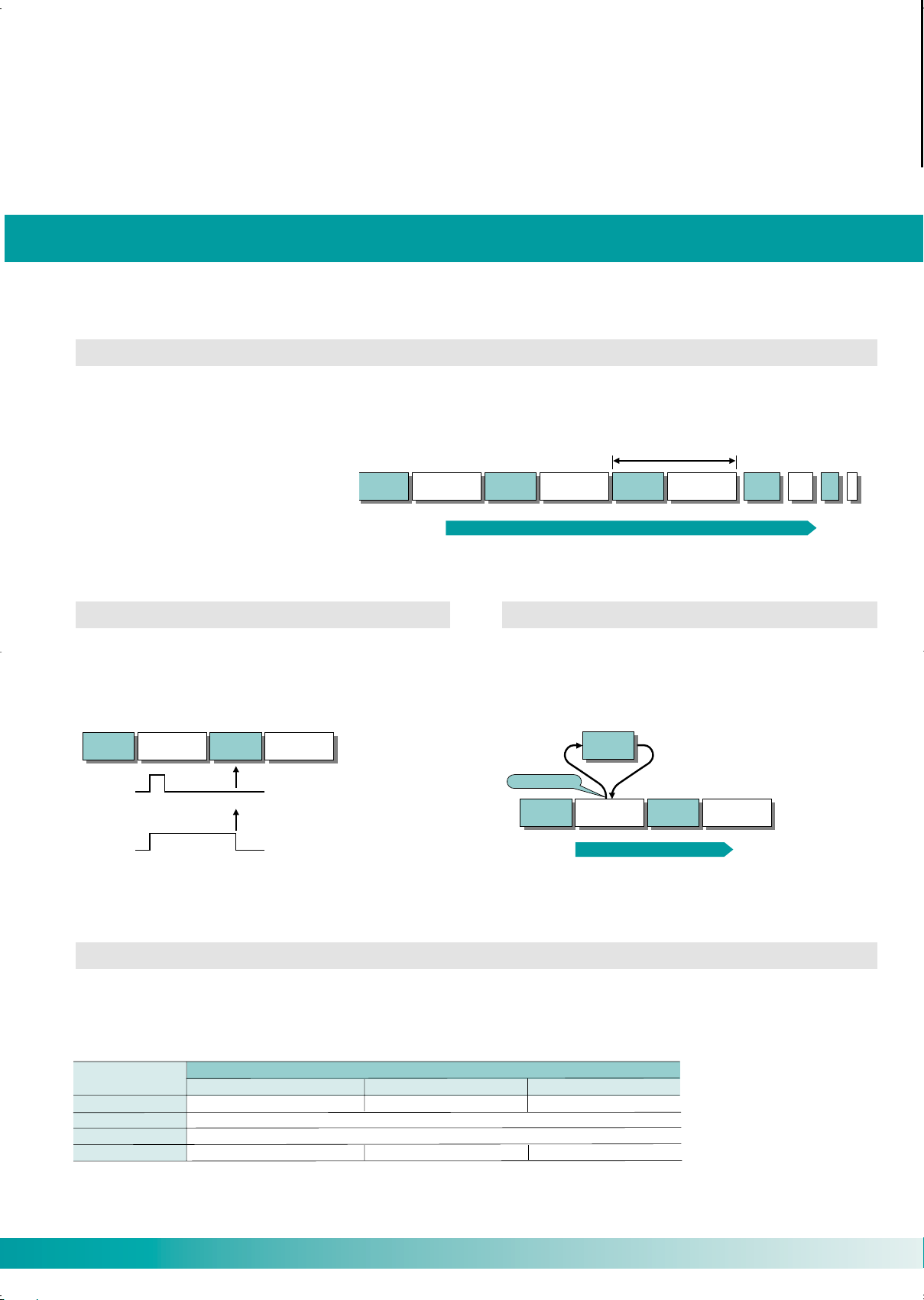
FP0 – Impressive Capabilities
I/O
refresh
Program
execution
I/O
refresh
Program
execution
1 scan
I/O
refresh
Program
execution
Internal processing in the FP0
I/O
refresh
Program
execution
I/O
refresh
Program
execution
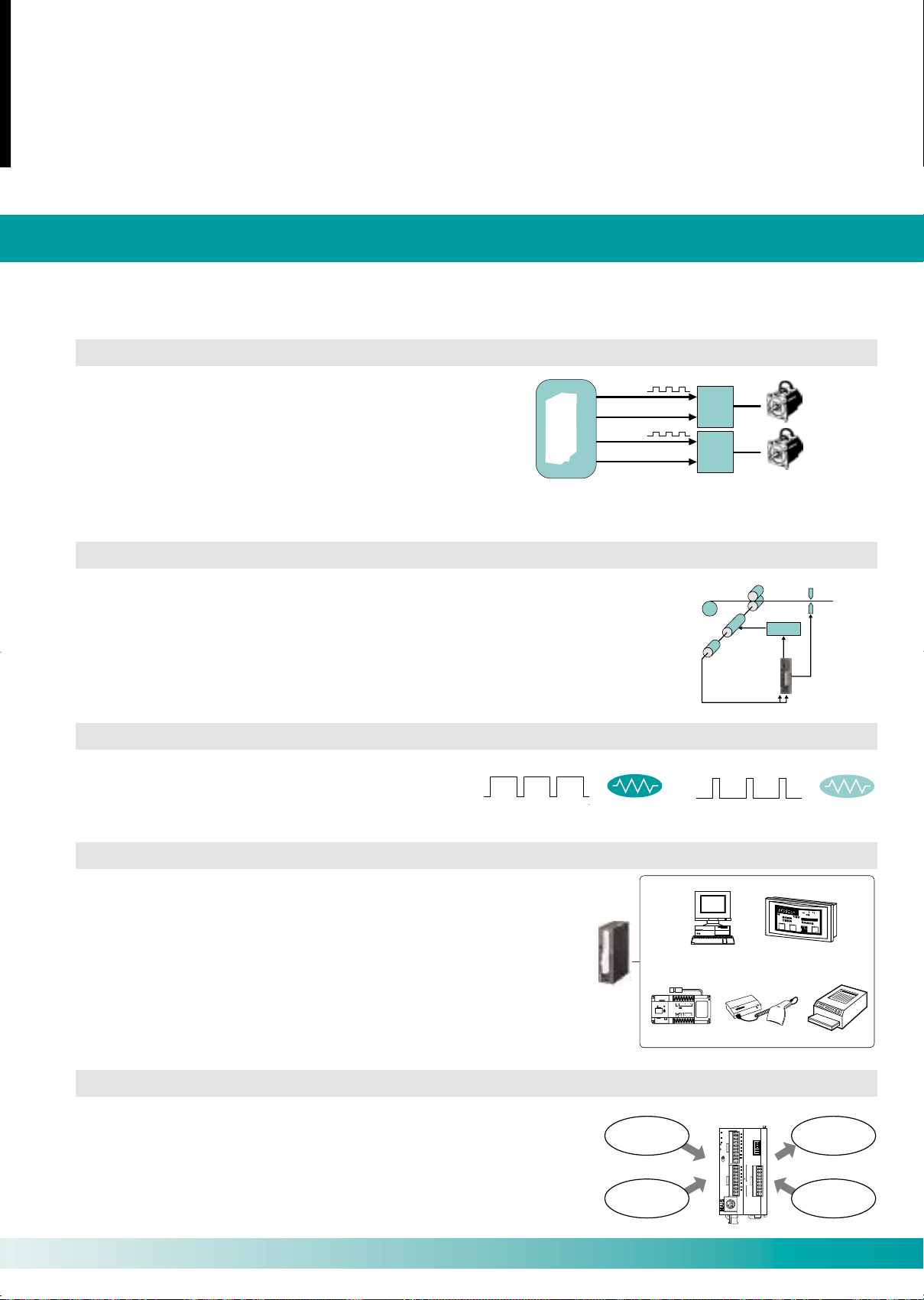
Sensor input
signal
Cannot
read.
Lengthening
of sensor
input signal
Can
read!
With pulse catch function
Internal processing in the FP0
I/O
refresh
Program
execution
I/O
refresh
Program
execution
Interrupt
program
Interrupt input
Interrupt program executed when
interrupt input enters.
I/O 10-point, 14-point, 16-point type
Control unit type
I/O 32-point type
2 720 steps
1 660 words
5 000 steps
6 144 words
1 008 points
144 points
FP0-T32 CP/T
10 000 steps
16 383 words
Program size
Internal relays
Timers/Counters
Data registers
CTi Automation - Phone: 800.894.0412 - Fax: 208.368.0415 - Web: www.ctiautomation.net - Email: info@ctiautomation.net
10/2004
High specifications for both speed and capacity
0.9µs per basic instruction. Pulse catch and interrupt input functions meet the need for high-speed response.
High-speed execution
Execution speed of 0.9µs per basic instruction. 500 steps program yields a scanning time of 1ms, which means the FP0
boosts the fastest processing time among the products of this class.
• Internal processing in the FP0
Pulse catch function
Can read pulses as short as 50µs, which greatly facilitates
sensor input.
Interrupt input function
Accurate processing, unaffected by scan time
• Interrupt input function
• Pulse catch function
Large capacity
A top-class large 5k and 10k steps program capacity housed within a compact body. Furthermore, data capacity for internal
devices like the data register is also ample. The unit's high performance is even suited to complicated controls
and controls with multiple amounts of data.
6
Page 7
FP0 – Impressive Capabilities
Y0
Y2
Motor
driver 1
Pulse output
Clockwise output/
counter-clockwise output
Y1
Y3
Motor
driver 2
Pulse output
Clockwise output/
counter-clockwise output
Feeder roller
Lead wiring,
tape
Cutter
Encoder
Motor
START/STOP
signal
Inverter
Cutter blade
control signal
Encoder output
inputted into
high-speed counter
Host computer
(Personal computer)
Operation
display panel
FP0
●
For connecting to computers and operation display panels
●
For data communication with RS232C devices
Imagechecker Bar code reader Serial printer
RS-232C
POWER READY
MODE
A
B
C
KEY PAD
CAMERA
MONITOR
COM COM D2 D4 D6 D8 D9
FLASH
D1 D3 D5 D7
READY
MICRO-IMAGECHECKER
M100
Matsuhita Electronic Works, Ltd.
24VDC
START
ACK IN1 IN3 IN5
COM COM IN2 IN4 COM
Heater
power up
● When pulse width values are increased...
● When reduced...
PROG.
RUN
ALARM
ERROR
PROG
RUN
Pressure sensor
Laser analogue
sensor
Inverter
Potentiometer
MODE
OFF ON
V 0
IN
I 0
COM
FP0 - A21
OUT
I 1
V
I
1
2
3
4
5
CTi Automation - Phone: 800.894.0412 - Fax: 208.368.0415 - Web: www.ctiautomation.net - Email: info@ctiautomation.net
10/2004
FP0 functions
Equipped with 2-axis independent positioning and high-speed counter for support of PWM output.
Pulse output function
(For transistor output type only) The unit comes equipped with
2 channels for the output of up to 10kHz pulses (5kHz during
2-channel output). Since these two channels can be separately
controlled, the PLC is also suitable for independent 2-axis
positioning. Setting automatic trapezoid control, automatic return
to home position and JOG operation are made very easy by using
instructions specially designed for such operations.
Positioning control is a breeze with
the auto trapezoid control command!
High-speed counter function
The high-speed counter is prepared for 4 channels in single phase, and 2 channels in
2-phase. In single phase, the 4-channel total is 10kHz, and in 2-phase the 2-channel total is
2kHz total speed, making the unit suitable for conveyer control, inverter control, and so
forth using an encoder.
PWM output function
Its PWM (Pulse Width Modulation) output function makes
it possible to provide temperature control with a single
compact FP0 unit. (For transistor output type only)
● When reduced...
Stepping
motor
Servo motor
Stepping
motor
Servo motor
power up
Heater
power down
Serial communication function
• The FP0’s second RS232C port (types C10CRS, C14CRS, C16C, C32C,
and T32C) allows direct connection to computers and operation display
panels. Also, bi-directional data communication with barcode readers
and other RS232C devices is made easy.
• Both the relay type and transistor output type control units are optionally
equipped with a 2nd RS232C port.
Analogue control function
Analogue control is made simple with four types of analoque modules
featuring different numbers of input and output channels.
Also, despite the small size, the I/O resolution is a high 1/4000 (12 bits).
Support various I/O ranges by setting the DIP switches on the analogue
I/O unit for simple operation.
7
Page 8

FP0 Communication
CTi Automation - Phone: 800.894.0412 - Fax: 208.368.0415 - Web: www.ctiautomation.net - Email: info@ctiautomation.net
10/2004
Serial interfaces and modem compatible
Communication – Simple and efficient via two serial interfaces: TOOL-Port and COM-Port (RS232C interface).
Programming interface TOOL-Port (also for communication)
In Computer Link mode, this port offers access to the entire FP0 memory area. For example during data exchange between
a host PC running SCADA software and an FP0 PLC, the Windows
the communications protocol (MEWTOCOL.COM). Therefore the user can disregard the allocation of data ranges and
transfer parameters, because there is no additional programming required. The programmer is thus free to concentrate
exclusively on the project application requirements.
®
based MEWNET-DDE Server assumes total control of
Communication Interface COM-Port
(flexible with two modes of operation, Computer Link and General Purpose)
In addition to the Computer Link communication possibilities described above, the optional integrated RS232C COM-Port
in the FP0 CPU module (types FP0-C10CRS, FP0-C14CRS, FP0-C16C, FP0-C32C and FP0-T32C) offers flexible programming
i.e. General Purpose. In this configuration it is possible to realise communication connections with different RS232C
peripheral devices, e.g. Bar Code Readers, slave devices, printers, measurement sensors or telecommunication
transmitters, etc.
Communication Interface COM-Port
Freely programmable RS232C interface for CPU modules type FP0-C10CRS,
FP0-C14CRS, FP0-C16C, FP0-C32C and FP0-T32C
Programming Interface TOOL-Port
For programming, and additionally Master/Slave communication, using
MEWTOCOL COM (Matsushita protocol)
Modem compatible
Even modem communication function is built into this compact body. Using a single telephone line,
programming maintenance can be carried out in remote facilities. With C-NET, multiple FPO units can be
connected.
■ 1:1 communication ■ 1:N communication ■ Multidrop communication
8
Page 9

FP0 Communication
CTi Automation - Phone: 800.894.0412 - Fax: 208.368.0415 - Web: www.ctiautomation.net - Email: info@ctiautomation.net
10/2004
Easier maintenance than ever before
Maintenance saving
Program memory uses EEPROM. In addition, programs can be changed even in RUN mode!
■ Overwrite function in RUN mode
It is possible to overwrite a program while the FP0 is running, such as during program debugging and startup
adjustments.
■ Backup battery unnecessary
The program memory uses EEPROM. The program and device contents can be stored without a backup battery, and
even programming for a machine builder is safe.
■ Password function
A password function can be set in order to change a program. Limited to people authorized to make program changes,
protection can be guaranteed better than ever.
■ Input/output verification LED
Every unit is equipped with LED I/O indicators, housed within a compact body. Input/output status can be verified
at a glance.
Simple installation
Comes with either terminal block or connector. Either type is easy to connect to wiring by simply
removing the terminal section.
Terminal block
Terminal type can be
plugged straight in without
resorting to crimping (made
by Phoenix Contact Co.).
Can handle wires from
0.3 to 1.25mm
Compatible models
FP0-C10RS, C10CRS, C14CRS, E8RS, E16RS
2
.
MIL connector
Unit connectors can be used
with 16-points and 32-points
units. Due to the loose-wiring,
pressure contact type design,
wiring is easy without the
need for insulation.
(MIL-C-83503)
Compatible models
FP0-C16T/C16P/C16CT/C16CP, C32T/C32P/C32CT/C32CP,
E16T/E16P, E32T/E32P,
FP0-T32CP/T32CT
9
Page 10

FP0 PROFIBUS DP Slave or Remote I/O Unit
CTi Automation - Phone: 800.894.0412 - Fax: 208.368.0415 - Web: www.ctiautomation.net - Email: info@ctiautomation.net
10/2004
For cost effective control of distributed field device
The FP0 DPS2 can operate either as a DP slave module or as a remote I/O
system to which different decentralised inputs and outputs can be
connected. A DIP switch can be used to switch between the two modes:
Mode 1:
DP-Slave module. Connect the FP0 or FP∑ (Sigma) CPU + expansion
modules to the PROFIBUS network.
Mode 2:
Remote I/O. Connect up to three expansion modules without CPU to the
PROFIBUS network.
In Remote I/O mode the unit can be connected to any PLC which offers a
PROFIBUS communication interface, making it totally independent of
NAiS PLCs.
FP0-DPS Specifications
Item Description
Type designation
PROFIBUS standards complied with
Baud rates
Range of adresses that can be set 0..125
PROFIBUS connection
Configuration
FP0 communication
Power supply 24VDC (21.6VDC … 26.4VDC)
Max. power consumption 100mA
DP-Slave
Remote I/O
FP0 DP Slave unit, Ord. No. FP0DPS2
EN 50170, DIN 19245 Part 1 and Part 3
9.6 / 19.2 / 93.75 / 187.5 / 500 / 1,500 / 3,000 / 6,000 / 12,000 Kbaud
automatic baud rate detection
9-pin D-sub connector
2 words input / 2 words output, up to 6 words input / 6 words output if no other expansion is connected
Remote I/O, max. 3 FP0 expansion units
Via FP0 system bus
Special developed software tools ensure
easy configuration and start-up of
PROFIBUS products.
AFP86910
FP2 DP or FMS Master
FP0 DP Slave FP∑ (Sigma) DP Slave
DP Slave Remote I/O
Configuration with digital I/O
up to 96 transistor I/O or up to
48 relay I/O are possible
DP Slave Remote I/O Configuration
with analogue I/O up to 12 outputs or
24 analogue inputs or up to 24
thermocouple inputs are possible
PLC
(Master)
PLC
(Slave)
Remote I/O
(Slave)
10
Page 11

FP0 S-LINK Unit
CTi Automation - Phone: 800.894.0412 - Fax: 208.368.0415 - Web: www.ctiautomation.net - Email: info@ctiautomation.net
10/2004
Connects directly to the S-LINK for reduced wiring
S-Link is a system which simplifies connection of rapidly increasing control devices accompanying
progressing automation and is useful in reducing your costs and construction time.
Features
1. Small size of only W30 x H90 x D60 mm.
Makes use of the T-shaped connectability of the S-LINK for reduced wiring and reduced size
of the control panel.
2. Controls 64 input points and 64 output points.
Able to control up to 128 points for S-LINK-related devices.
3. Allows simultaneous use of expansion units.
Similar to other FP0 units, up to three expansion units can be used for efficient I/O wiring.
FP0-SL1
4. A wide range of I/O modules allow manifold customer-oriented network layouts.
Power Supply Specification
Item Description
Power supply 24VDC
Performance Specifications
Item Description
Number of I/O points
Expansion
Operation speed 0.9µs/step
Internal memory
Memory capacity 5k steps
Memory Internal relay
of
execution
Timer/Counter
Data register
S-LINK block: 64 input points,
64 output points (fixed)
Max. 3 units
Expansion section:
Max. 96 points
EEPROM
1,008 points
144 points in total
6,144 words
Applicable Functions
Item Description
Pulse catch/Interrupt input
Analogue I/O
Volume input
High-speed Counter
Pulse output None
RS232C port
None
Available by adding analogue I/O unit
None
None
1 ch is equipped.
3P terminal blocks (made by
Phoenix Contact Co.)
Applicable Network
Item Description
Control unit functions as S-LINK
Remote I/O
Inter-PLC link
Computer link
Modem connection
master station.
Available as a slave station of
MEWNET-F by adding I/O link unit
Not available
Linkable with tool port or
RS232C port
Available, Type with RS232C
port can also send data
Other Built-in Functions
Item Description
Program block-edit
during RUN
Constant scan
Adjustable input time
filtering
Clock/Calendar function
Available
Available
Not available
None
Direct connection for reduced wiring
FP0
S-LINK Control unit
W30 × H90 × D60
T-branch multi
drop wiring
The layout of devices becomes flexible
and the design is easier due to the
‘T’-branch multi-drop wiring.
Maximum length: 200m
Max. 128 points
2 signal wires
2 power
supply wires
Wire-saving
The use of wires is greatly reduced and the number of connecting
terminal blocks is minimized, resulting in large reduction in cost, as
well as, the waste generated during wiring.
Space effective
S-Link devices are compact. The control box can be mounted in a
tight space.
Quick construction
Sensors cab be easily connected with plug-in connection.
11
Page 12

FP0 MEWNET-F Unit
FP2 (Master station)
FP0 (Slave station) FP0 (Slave station) FP0 (Slave station)
Twisted pair cable or VCTF
C-NET
adapter
AC 100 to 200V
24V DC
: AFP8536
: AFP8532
C-NET
adapter
S2 type
(AFP15402)
Max. 32 units
Max. 1,200 m
FP0
( )
CTi Automation - Phone: 800.894.0412 - Fax: 208.368.0415 - Web: www.ctiautomation.net - Email: info@ctiautomation.net
10/2004
Networking units
MEWNET-F
The FP0 can be used as a slave station for MEWNET-F (remote I/O system) by adding I/O link unit.
MEWNET-F is a reduced-wiring remote I/O system that connects PLCs
located separately and I/O slave stations with 2-core cabling. By adding an
I/O link unit to the FP0, you can link master station PLC and FP0 inputs and
outputs via the network.
FP0-IOL FP0-IOL FP0-IOL
FP0-IOL Link Unit Specifications
Item Description
Communication method
Synchronous system
Transmission line 2-wire cable (Twisted-pair cable or equivalent to VCTF 0.75 mm2x 2C)
Transmission distance
(Total distance)
Transmission speed (Baud rate) 0,5Mbit/s
Number of control I/O points
per an I/O link unit
Remote I/O map allocation
Interface
Transmission error check
Two-wire, half duplex transmission
Start stop synchronous system
Max. 700m per port (using twisted pair cable)
Max. 400m per port (using VCTF cable)
64 points
(Input: 32 points and Output: 32 points)
32X/32Y
Conforms to RS485
CRC (Cyclic Redundancy Check) method
C-NET
By using C-NET, you can use multiple FP0s as data collection terminals.
By using the C-NET network and exclusive
adapters, you can connect multiple FP0s by
multi-drop connection with 2-wire cables.
You can use computers for separate control
or have network terminals for a centralized
management system.
MEWNET-F Slave
FP0-IOL
12
Page 13

FP0 Thermocouple Input Expansion Units
CTi Automation - Phone: 800.894.0412 - Fax: 208.368.0415 - Web: www.ctiautomation.net - Email: info@ctiautomation.net
10/2004
Enable high precision temperature control at low cost
The FP0-TC4 and FP0-TC8 thermocouple units are suitable for user
friendly temperature acquisition using standard thermocouples with
high precision.
■ Up to three units can be added to each control unit, enabling
temperature control of up to 24 channels.
■ The temperature data obtained using the thermocouple is converted to
the digital value to be read into the FP0 control unit.
■ Standard types of thermocouples can be used: K, J, T and R
■ 3 temperature measurement ranges are available:
-100°C to +500°C (Thermocouple types: K and J)
-100°C to +400°C (Thermocouple type : T)
- 0°C to +1500°C (Thermocouple type : R)
■ The temperature data measured using the sensor is converted to
degrees Celsius or degrees Fahrenheit inside the Thermocouple Unit.
■ The converted data (°C or °F) is averaged, so that even unstable input
signals can be properly read.
■ Broken thermocouples can be detected.
FP0-TC4 and FP0-TC8 specifications
Temperature control
FP0 TC8
8 channels
FP0 TC4
4 channels
Item Specification
Input points
Input range
Resolution 0.1°C
Sampling cycle
Accuracy
Input Impedance
Insulation method
Up to 8 channels per unit (The number of input points can be changed 2, 4, 6 and 8 channels are available)
Thermocouple types K, J -100°C to 500°C
Thermocouple types T -100°C to 400°C
Thermocouple types R 0°C to 1500°C
300ms: when using 2 channels for an input points
500ms: when using 4 channels for an input points
700ms: when using 6 channels for an input points
900ms: when using 8 channels for an input points
Range for K and J (-100°C to 500°C): 0.8°C
Range for T (-100°C to 400°C): 0.8°C
Range for R (0°C to 99.9°C): 3°C
more than 1MΩ
- between thermocouple input terminals and control unit internal circuits Photo-coupler insulation/DC-DC insulation
- between thermocouple input terminal channels PhotoMOS relay insulation
(100°C to 299.9°C): 2.5°C
(300°C to 1500°C): 2°C
13
Page 14

Analogue Signal Processing
CTi Automation - Phone: 800.894.0412 - Fax: 208.368.0415 - Web: www.ctiautomation.net - Email: info@ctiautomation.net
10/2004
FP0 Analogue Units
Features
FP0-A21
2 Inputs/1 Output
■ Multimode A/D, D/A conversion ■ High resolution: 12-bit
Voltage, current and temperature selectable
■ 2 analogue inputs (FP0-A21): ■ High conversion speed
-10 to + 10V, 0 to 5V, 0 to 20mA, FP0-A04V, FP0-A04I: 500µs
8 analogue inputs (FP0-A80):
-10 to + 10V, 0 to 5V, -100 to + 100mV, 0 to 20mA ■ PID instruction with auto tuning
■ 1 analogue output (FP0-A21): -10 to + 10V, 0 to 20mA
4 analogue outputs (FP0-A04V): -10 to + 10V ■ Screw terminal connection
4 analogue outputs (FP0-A04I): 4 to 20mA
The analogue units can be used with the FP0 and FP∑ (Sigma) so wide range applications are possible from smallscale machines to factory production systems.
Each CPU supports up to 3 FP0 analogue units. Combination with digital and analogue expansion units is freely allowed.
Highest performance is offered with 12-bit resolution. With a current and voltage output conversion time of up to
500µs, the units are capable of high-speed processing.
FP0-A80
8 Inputs
FP0-A04V
4 Outputs
FP0-A04I
4 Outputs
The multimode FP0 analogue unit can be configured via the DIP switches on the front side into the required analogue
ranges. Communication with the FP0 CPU unit is achieved via the expansion bus. The expansion bus is automatically
connected after the FP0 analogue unit is connected to the FP0 CPU unit.
Note: Function Blocks for FPWIN Pro Programming System can be downloaded free of charge from our WEB-page.
14
Page 15

Analogue Signal Processing
CTi Automation - Phone: 800.894.0412 - Fax: 208.368.0415 - Web: www.ctiautomation.net - Email: info@ctiautomation.net
10/2004
FP0 Analogue Units
General specifications
Item Description
Rated operating voltage
Operating voltage range
Rated current consumption FP0-A80: 60mA or less, FP0-A21/A04V: 100mA or less, FP0-A04I: 130mA or less
Ambient temperature 0°C to +55°C
Storage temperature -20°C to +70°C
Size 90 x 25 x 60mm
Weight appoximately 100g
Analogue input specification
24VDC
21.6 to 26.4VDC
Item
Product
Number of channels
Input range selectable
( 2 CH)
Digital output
Resolution
Conversion speed
Overall accuracy
Input impedance
Maximum input
Insulation
FP0 input address
(*1) K means decimal constants.
(*2) Reference temperature → Reference points is start points.
(*3) Reference temperature → Reference points is end points.
(*4) The address varies depending on the position of the analogue unit. (WX2/3, WX4/5 or WX6/7)
Voltage mode 0 to 5V/-10V to +10V
Current mode 0 to 20mA
Thermocouple mode K, J, T type thermocouple
0 to 5V/0 to 20mA: K 0 to K 4000 (H 0000 to H 0FA0) (*1)
-10 to +10V (-100 to +100mV): K -2000 to K +2000 (HF830 to H07D0)
Thermocouple: The value of broken wire detection is K 20000.
Voltage/current mode: 1ms/channel
Thermocouple mode: 560ms/channel
Thermocouple mode: Offset error (0 to 55°C), 2% for full-scale (K-type)
DC/DC converter insulation between analogue input terminal and analogue output terminal
32 input contact points: First 16 points analogue input CH0 data (WX2) (*4)
K up to 1000°C or -100°C to terminal temperature (selectable)
J up to 750°C or -100°C to terminal temperature (selectable)
T up to 350°C or -100°C to terminal temperature (selectable)
For plus: K temperature of terminal (*2) to K 1000 (Unit is Celsius)
For minus: K-100 to K temperature of terminal (*3) (Unit is Celsius)
linearity error (0 to 55%): 1% for full scale
Last 16 points analogue input CH1 data (WX3) (*4)
FP0-A21 FP0-A80
2 channels/unit 8 channels/unit
Voltage/current mode: 1% for full-scale (0 to 55°C), 0.6% for full-scale (at 25°C)
2.7% for full-scale (J-type)
5.8% for full-scale (T-type)
Optical coupler insulation between analogue input terminal and FP0 internal circuit
DC/DC converter insulation between analogue input terminal and analogue I/O unit external power supply
(No insulation between analogue inputs)
Description
12 bits (1/4000)
Voltage mode: 1M ohm or more
Current mode: 250ohm
Voltage mode: +/- 15V
Current mode: +30mA
-100 to +100mV/0 to 5V / -10V to +10V
–
–
2ms/channel
–
–
0 to 20mA
32 input contact points:
First 16 points analogue input
CH0, 2,4,6 data (WX2) (*4)
Last 16 points analogue input
CH1,3,5,7 data (WX3) (*4)
Analogue output specification (FP0-A21)
Item Description
Product
Number of channels
Output signal selectable
Digital input (*1)
Resolution
Conversion speed
Overall accuracy
Output impedance
Maximum output current
Allowable output load
resistance
Insulation
Reserved CPU addresses (*4)
Voltage mode -10V to +10V
Current mode 0 to 20mA
0 to 20mA: 0 to 20mA: K 0 to K 4000
-10V to +10V: -10V to +10V: K -2000 to K+2000
FP0-A21 FP0-A04V FP0-A04I
1 4 4
-10V to +10V
K -2000 to K+2000 K 0 to K 4000
500ms 500µs 500µs
less than 300Ω 1000Ω or more less than 500Ω
DC/DC converter insulation between analogue output terminal and analogue I/O unit external power supply
16 output points 32 output points 32 output points
1% for full-scale (0 to 55°C), 0.6% for full-scale (at 25°C)
Optical coupler insulation between analogue output terminal and FP0 internal circuit
DC/DC converter insulation between analogue output terminal and analogue input terminal
12 bits (1/4000)
Voltage mode: less than 0.50Ω -
Voltage mode: +/- 10mA -
4 to 20mA
15
Page 16

FP0 RTD Input Expansion Unit
CTi Automation - Phone: 800.894.0412 - Fax: 208.368.0415 - Web: www.ctiautomation.net - Email: info@ctiautomation.net
10/2004
User friendly acquisition of temperatures with high precision
Features
■ The module can be easily installed in an existing system: Special
connection cables, backplanes, and so forth are unnecessary as the
expansion unit employs a stacking system that uses expansion
connectors and lock levers on the surface of the unit itself.
■ Multiple RTD types are allowed in one module, creating a cost-effective
solution.
■ About the Application areas:
- Measurement and control equipments
- Process and Machine controls
- Greenhouse and Agro industries
FP0-RTD6
6 channels
Take advantage of the various FPWIN Pro libraries with many functions and function blocks. These ready-made programs can be saved and reused time and again and will help you to shorten the time needed to develop applications
drastically, and consequently to save valuable human resource costs.
Controller Library: NCL-MR-LIB
The programmable logic arrays of the controller library simplify
the programming of closed loop controlled electrical installations.
The library includes linear and non linear controller types such as
the P/I/PI/PID controller and two points-/three-points controller with
and without hysteresis. Programmable logic arrays for dead band,
interpolation, lamp limiting, dead time and averaging are also included.
FP0-RTD6 specifications
Item Specification
Input points
Input type
Sampling cycle
Temperature resolution
Accuracy
at ambient temperature: 0-55°C
Accuracy
at ambient temperature: 25°C
Size
Up to 6 channels per unit
- 3 inputs per one Phoenix screw terminal
- for every sensor 3 screws
Pt 100 -200°C to 500°C (3 wire)
Pt 1000 -100°C to 200°C (2 wire)
Ni 1000 -30°C to 150°C (2 wire)
Resistor measurement
0.1sec / 1sec for 6 channels
- depending on the switch setting
(slower cycle timer = higher accuracy)
0.1 K
cycle time 0.1 sec: Pt 100: 0.5%/3.5K, Pt 1000: 05%/2.5K, Ni 1000: 2K, Resistor:2Ω
cycle time 1 sec: Pt 100: 0.35%/2.5K, Pt 1000: 035%/1.7K, Ni 1000: 1K, Resistor:1Ω
cycle time 1 sec:
W 25 x H 90 x B 60 mm
Pt 100: 0.3K from -10 to +30°C, 0.2%/1.4K from -200 to +500°C
Pt 1000: 0.3K from -10 to +30°C, 0.2%/1.0K from -200 to +300°C
16
Page 17

Item Description
Rated operating voltage 24 VDC
Operating voltage range 21.6 to 26.4 VDC
Allowable no voltage time
10 points, 14 points type
5ms (at 21.6 V), 10ms (at 24 V)
16 points, 32 points, S-LINK type
10ms (at 21.6 V / 24 V)
Ambient temperature 0°C to +55°C
Storage temperature -20°C to +70°C
Ambient humidity 30 to 85% RH (Non-condensing)
Storage humidity 30 to 85% RH (Non-condensing)
Breakdown voltage
Between input/output terminals and power/ground terminals: 500VAC for 1 minute (for the relay output type, 1500VAC for 1 minute)
Between input terminals and output terminals: 500VAC for 1 minute (for the relay output type, 1500VAC for 1 minute)
Insulation resistance
Between input/output terminals and power/ground terminals: Over 100 MΩ (using a 500VDC megger)
Between input terminals and output terminals: Over 100MΩ (using a 500VDC megger)
Vibration resistance 10 to 55Hz, 1 sweep/min., double amplitude of 0.75mm, 10min. on 3 axes
Shock resistance
98m/s
2
or more, 4 times on 3 axes
Noise immunity 1,000 V(p-p) with pulse widths 50ns and 1ms (using a noise simulator)
Operating condition Free from corrosive gasses and excessive dust
Type of control unit
C10 series C14 series C16 series C32 series
S-LINK type
T32 series
Programming method / Control method Relay symbol/Cyclic operation
Number of
I/O points
No expansion
(control unit only)
Total: 10
Total: 14
Total: 16
Total: 32
Total: 32
W/expansion 1
*Same type of control and expansion units
Max. 58 Max. 62 Max. 112 Max. 128
Expansion section:
max.96 points
Max. 128
W/expansion 2
*Mix type of relay and transistor units
Max. 106 Max. 110 Max. 112 Max. 128 Max. 128
Program memory EEPROM (No back-up battery required)
Program capacity 2.7K steps 5K steps 10K steps
Kinds of
instruction
Basic 83
High-level 115
Operation speed (central value/step) 0.9µs (Basic instruction)
Memory for
execution
Relay
Intermal relay (R)
1,008 points
Timer/Counter (T/C)
144 points
Memory
area
Data register (DT)
1,660 words 6,144 words 16,384 words
Index register(IX,IY)
2 words
Master control relay (MCR) 32 points
Number of labels (JMP and LOOP) 64 labels 255 labels
Differential points Unlimited number of points
Number of step ladder 128 stages 704 stages
Number of subroutines 16 subroutines 100 subroutines
Special
functions
High speed counter
1 phase/4 points (10kHz in total) or 2 phases / 2 points (2kHz in total)*
Not available
Pulse output Not available
2 points (10 kHz* in total),enable to control 2
channels individually*
Not available
PWM output Not available 0.15Hz to 1kHz Not available
Pulse catch input/interrupt input
6 points(with high speed counter) Not available
Interrupt program 7 programs (external 6 points, internal 1 point)
Periodical interrupt 0.5ms to 30s
Constant scan Available
RS232C port
One RS232C port is mounted on each of the models FP0- C10CR, C14CR,C16CT, C16CP, C32CT, C32CP, T32CT, T32CP and SL1 type (3P terminal block)
Transmission speed (Baud rate): 300 to 19200bits/s , 3m Communication method: half duplex
Transmission distance: 3m
Maintenance
Memory
back up
Stored program and system register in EEPROM
Operation
memory
Stored fixed area in EEPROM
Counter: 4 points
Internal relay: 32 points
Data register: 8 words
Counter: 16 points
Internal relay: 128 points
Date register: 32 words
Backup is provided by
secondary battery. The
holding range for the
timers, counters, internal
relays, and data registers are specified with
the programming tool.
Self-diagnosis functions Watchdog timer, program syntax checking, etc.
Clock/calender function Not available Available
Other functions Runtime editing, password setting
* For the limitations while operating units, see the manual.
Stored fixed area in EEPROM
Total:128
(Input: 6, Output: 4) (Input: 8, Output: 6) (Input: 8, Output: 8) (Input: 16, Output: 16) (Input: 64, Output: 64) (Input: 16, Output: 16)
Program and system register
(Relay output type only) (Relay output type only)
(Transistor output type only) (Transistor output type only) (Transistor output type only)
Available (same as
32 points series)
1 program (internal 1 point)
Available (same as
32 points series)
FP0 Series
CTi Automation - Phone: 800.894.0412 - Fax: 208.368.0415 - Web: www.ctiautomation.net - Email: info@ctiautomation.net
10/2004
Specification tables
FP0 Specifications
General Specifications
17
Page 18

FP0 Series
CTi Automation - Phone: 800.894.0412 - Fax: 208.368.0415 - Web: www.ctiautomation.net - Email: info@ctiautomation.net
10/2004
Specification tables
Interfaces
Item Description
Programming TOOL-Port
Communication COM-Port
RS232, mini DIN socket (5 pin), 9600 or 19200 BAUD, (8 data bits, odd parity, 1 stop bit), Computer link for
programming and communication with MEWTOCOL.COM, user configurable modem connection
RS232 (SD, RD, GND) 3 way screw terminal, 300 to 19200 BAUD, (7 or 8 data bits, none/even/odd parity,
1 or 2 stop bits, start code: none/STX, end code: CR/CR+LF/ETX/none, CCU mode for programming and
communication with MEWTOCOL.COM, user configurable modem connection, GENERAL PURPOSE MODE
controlled by program for general purpose RS232 communication.
Input specifications
Item
Insulation method Optical coupler
Rated input voltage 24VDC
Operating voltage range 21.6 to 26.4VDC
Rated input current 4.3mA or less (at 24VDC)
Input points per common
ON voltage/ON current 19.2V or less/ 3mA or less
OFF voltage/OFF current 2.4V or more/ 1mA or more
Input impedance Approx. 5.6kΩ
OFF➔ ON
Response time
ON➔ OFF
Operating indicator LED display
Note: (*): Since the response time of X0 to X5 is very fast (for high-speed counter input), the FP0 happens to catch chattering noise as an input signal.
To prevent this, it is recommended that timer instruction should be included in the program.
6 points/common (C10RS) 8 points/common (C14RS,C16T/C16P,E16T/E16P) 16 points/common (C32T/C32P,E32T/E32P)
50µs or less (at X0,X1)(*)
100µs or less (at X2 to X5)
2ms or less (at X6 to XF)
same as above
Description
Output specifications
1) Relay output type
Item
Output type Normally open(1 Form A)
Rated control capacity
Response time
Life
Surge absorber None
Operation indicator LED display
The FP0 series conforms to the following standards under the EMC Directive
and the Low Voltage Directive.
EMC Directive (89/336/EEC) Low Voltage Directive (73/23/EEC)
EN 50081-2: 1993 VDE 0160: 1988 (EN 50178: 1995)
EN 50082-2: 1995 (Overvoltage Category II,
OFF➔ ON
ON➔ OFF
Mechanical
Electrical
2A 250VAC, 2A 30VDC(4.5A/common)
10ms or less
8ms or less
20million operations or more
100k operations or more
Description
non-mains-circuit, pollution degree 2)
EN 61131-2: 1995
2) Transistor output type
Item
Insulation method Optical coupler
Output type Open collector
Rated load voltage 24VDC 5 to 24VDC
Load voltage allowable range 4.75 to 26.4VDC
Max. load current
Max. inrush current 0.3A
Leakage current at OFF time 100µA or less
Max. voltage down at ON time
External power
supply
(For internal circuit)
Response time
Surge absorber Zener diode
Operating indicator
Notes:
(*1): 8points/common(C16T/C16P,E16T/E16P), 16points/common(C32T/C32P,
T32CP, E32T/E32P)
(*2): 50µs or less at Y0, Y1 only
Voltage 21.6 to 26.4VDC
Current 240mA or less
OFF➔ ON
ON➔ OFF
0.1A/points(at DC26.4V) (1A/common)(*1)
1.5V or less
1ms or less
1ms or less(*2)
LED display
Description
18
Page 19

Control FPWIN Pro
FP Programmer II Ver. 2
Programming cable
AFC8513D
Programming cable
AFC8523
Programming
software
Connect with RS232C cable
FP0
CTi Automation - Phone: 800.894.0412 - Fax: 208.368.0415 - Web: www.ctiautomation.net - Email: info@ctiautomation.net
10/2004
PLC programming software conforming to IEC 61131-3
Control FPWIN Pro is the Matsushita programming software according to the international standard IEC 61131-3.
Control FPWIN Pro works with the FP0 as well as any FP series programmable controller. Also, since the tool port is an
RS232C, connection to a PC is easy – it only requires a single cable. No converter or adapter is required.
Control FPWIN Pro – Programming
The most important highlights at a glance:
■
Reuse of ready made functions and function blocks saves time for programming and debugging
■
5 programming languages (Instruction List, Ladder Diagram, Function Block Diagram,
Sequential Function Chart, Structured Text)
■
Convenient comment application in 6 languages (English, German, French, Italian, Spanish, Japanese)
■
4 standard libraries (IEC Standard library, Matsushita library (M Lib), Pulsed library (P Lib), NC Tool library (NC Tool Lib))
■
Fewer errors through defined data types and encapsulation
■
Well-structured through programme organisation units, task-
and project management
■
Online monitoring and diagnostic
■
Ethernet and Modem communication for remote-programming,
-service, and -diagnostic
■
Password protection with different levels
■
Many additional application libraries available
■
IEC 61131-3 protects your investments for the future
19
Page 20

Control FPWIN GR
CTi Automation - Phone: 800.894.0412 - Fax: 208.368.0415 - Web: www.ctiautomation.net - Email: info@ctiautomation.net
10/2004
PLC programming software for easy operation
Features
FP Series programming software for Windows.
1. To facilitate operation on site, a mouse is not required for input, search, write, monitor and timer edit operations.
Everything can be accomplished with a keyboard alone.
2. Standard Windows operations, such as copy and paste, are included.
3. Supports all FP series machines. Software created with NPST-GR Ver. 3 or 4 can also be used.
4. Inherits convenient functions developed for NPST-GR.
Usage environment
OS
Required hard disc capacity
Recommended CPU
Recommended installed memory
Recommended screen resolution
Recommended display colors
Menu
Program status display
Program display
Windows 95/98/NT (Ver. 4.0 or later)/XP
At least 30MB
Pentium 100MHz or higher
32MB or more
800 x 600 or higher
High Color (16-bit or higher)
Applicable PLC types
*All products on the market are supported.
All FP series types are supported:
FP∑ Sigma, FP0, FP-e, FP1, FP2, FP2SH, FP3, FP10SH, FP-M
Note: FPWIN GR Vers. 2.2 or later is needed to program the FP-e
Tool bar
Access often-used
functions using icons.
Function bar
Provides information
regarding command
input and confirmation,
on-line/off-line
selection and PLC
mode selection.
Function instruction list
Classified by type, function
commands can be selected
from the displayed list.
(Simple help included.)
I/O comment edit function
Successive I/O comments can
be input for each device type.
Data from Excel and other
applications can be copied and
pasted via the clipboard.
Status display
Displays information
concerning PLC usage
environment and settings,
and detailed information
when an error occurs.
20
Page 21

Control CommX, PCWAY, OPC Server
Plant
CTi Automation - Phone: 800.894.0412 - Fax: 208.368.0415 - Web: www.ctiautomation.net - Email: info@ctiautomation.net
10/2004
Visualisation software for ready made or customised solutions
Control CommX
The connection in ActiveX technology.
■
Connects your Visual Basic application to Matsushita PLCs.
■
Gives you the possibility to easily develop highly customised control solutions.
■
Create your own application very quickly by simply adding the functionality of ActiveX control to your code written with
Visual Basic.
■
No knowledge of MEWTOCOL (Matsushita's PLC communication protocol) needed.
Setup Process
Initial Setup in Visual Basic Configuration of Communication Register of Various Programming
▲
▲
Communication Types
▲
PCWAY
Add-on software for Excel to monitor and change PLC data.
■
The Excel add-in software PCWAY is available for data collection of the networked
PLCs. The contents of the PLC bits and data registers can be simply shown and
managed on Excel worksheets.
■
Settings in PCWAY can be used to switch display contents and character colour
corresponding to contact on/off status and register values, and perform calculations
based on register values. Excel macros are not necessary.
MEWTOCOL OPC Server
The connection between PLC and SCADA software.
■
Provides a standard interface between our FP Series PLCs and various
SCADA/HMI software* used to build a monitoring system compliant
with commercially available OPC clients. It is also possible to use OPC
automation interface to link our FP series PLCs with Visual Basic.
■
OPC (OLE for Process Control) is an interface standard for linking
software with various companies’ control devices. This standard
allows connections between OPC-compliant products.
Remote
supervisory
control
▲
Completion
* We have confirmed linking with iFIX Ver.2.6 (Intellution),
InTouch Ver.7.0 (Wonderware), and RSView32 Ver.6.3 (Rockwell Software).
Plant
Plant
21
Page 22

FP0 Control and Expansion Units
CTi Automation - Phone: 800.894.0412 - Fax: 208.368.0415 - Web: www.ctiautomation.net - Email: info@ctiautomation.net
10/2004
Products and order numbers
Control units
Relay output type
Order number: FP0-C10RSA
Transistor output type
Order number: FP0-C16PA (PNP)
Expansion units
10 points
Input 6 points
Output 4 points
Terminal type
16 points
Input 8 points Output 8 points
PNP/NPN output type
FP0-C16TA (NPN)
Relay output type Input only type
10 points
Input 6 points Output 4 points
Terminal type
Order number: FP0-C10CRSA
with 2nd RS232C interface
16 points
Input 8 points Output 8 points
PNP/NPN output type
Order number: FP0-C16CPA (PNP)
FP0 -C16CTA (NPN)
with 2nd RS232C
interface
14 points
Input 8 points Output 6 points
Terminal type
Order number: FP0-C14RSA
32 points
Input 16 points
PNP/NPN output type
Order number: FP0-C32PA (PNP)
Output 16 points
FP0-C32TA (NPN)
14 points
Input 8 points Output 6 points
Terminal type
Order number: FP0-C14CRSA
with 2nd RS232C interface
32 points
Input 16 points
PNP/NPN output type
Order number: FP0-C32CPA (PNP)
Output 16 points
FP0-T32CPA (PNP, 10K)
FP0-C32CTA (NPN)
FP0-T32CTA (NPN, 10K)
with 2nd RS232C
interface
Input 4 points
Terminal relay type
Order number: FP0-E8RSA
Output 4 points
8 points
Order number: FP0-E16RSA
16 points
Input 8 points Output 8 points
Terminal relay type
8 points
Input 8 points
Order number: FP0-E8XA
16 points
Input 16 points
Order number: FP0-E16XA
Transistor output type
8 points
Output 8 points
PNP/NPN output type
Order number: FP0-E8YPA (PNP)
Order number: FP0-E16YPA (PNP)
FP0-E8YTA (NPN)
Notes:
■ A power cable (order number AFP0581) is enclosed with the control unit and the relay output type upgrade units (Transistor output type upgrade units do
not require a power cable).
■ Two Phoenix terminals (9-pin) are needed with the relay output type terminal type. A 2.5mm width screwdriver is needed for the wiring.
Have ready a dedicated terminal screwdriver (order number AFP0806: Phoenix order number SZS0, 4 X 2.5 compatible), or equivalent.
■ A loose-wiring pressure socket and contact (2 pins with order numbers FP0-C16T/P, E16T/P, and 4 pins with order numbers FP0-C32T/P, E32T/P) are needed
with the transistor output type. A loose-wiring connector pressure contact tool (order number AXY52000) is needed for the wiring.
16 points
Output 16 points
PNP/NPN output type
FP0-E16YTA (NPN)
16 points
Input 8 points Output 8 points
PNP/NPN output type
Order number: FP0-E16PA (PNP)
FP0-E16TA (NPN)
32 points
Input 16 points
PNP/NPN output type
Order number: FP0-E32PA (PNP)
Output 16 points
FP0-E32TA (NPN)
22
Page 23

FP0 Analogue and Networking Units
CTi Automation - Phone: 800.894.0412 - Fax: 208.368.0415 - Web: www.ctiautomation.net - Email: info@ctiautomation.net
10/2004
Products and order numbers
Analogue units
Input 2 points
Order number: FP0-A21A
3 points
Output 1 points
Terminal type
Temperature control units
4 points
Input 4 points
Terminal type
Order number: FP0-TC4
Networking units
8 points
Input 8 points
Terminal type
Order number: FP0-A80A
8 points
Input 8 points
Terminal type
Order number: FP0-TC8
4 points
Output 4 points
Terminal type
Order number: FP0-A04V
6 points
Input 6 points
Terminal type
Order number: FP0-RTD6
4 points
Output 4 points
Terminal type
Order number: FP0-A04I
Handy Programmer
PROFIBUS
PROFIBUS
DP-Slave or Remote I/O
Order number: FP0-DPS2
AC power supply
Input
85 to 265VAC
Terminal type
Order number: FP0-PSA2
Output
24V DC/ 0.7A
MEWNET-F
MEWNET-F
Slave
Order number: FP0-IOL
Input
85 to 265VAC
Terminal type
Order number: FP-PS24-050E
Output
24VDC/ 2.1A
S-LINK CPU
S-LINK
Master
Order number: FP0-SL1
FP Memory Loader
Read or write programs from
or to a PLC
Order number: AFP8670
FP Programmer Ver. 2
Order number: AFP1114V2
23
Page 24

Terminal screwdriver
Necessary when wiring relay output type & terminals (Phoenix).
Attachment example
Wiring tools Parts for attachment I/O cables & networks
Order number
: AFP0806
Slim attachment plate model
Screw-stop attachment plate. Slim model.
Order number
: AFP0803 (set of 10)
Attachment example
DIN rail attachment
example
Flat attachment plate model
Screw-stop attachment plate. Flat model.
<Length 1m > 2 cable set
<Length 3m > 2 cable set
Transistor output type I/O cable
Loose-wiring cable (10 leads) AWG24 with connectors
attached at one end, 1 set: 2 cables
Order number
: AFP0804 (set of 10)
Input simulator
for FP0 relay output type, 6 switches
Order number
: SWITCH-FP0
Loose-wiring connector pressure contact tool
Necessary when wiring transistor output type connectors.
Order number
: AXY52000
Order number
:
AT8DLA1
C-NET adapter S2 type
Adapter for linking to a higher-placed computer.
With 30cm dedicated cable. Power source unnecessary.
Order number
: AFP15402
DIN rail
Standard DIN rail of width 35mm 1.378inch
and length 1m.
Order
number:
Stopper fitting
DIN rail stopper fitting.
ATA4806
Order
number:
AFP0521
Order
number:
AFP0523
Accessories
Terminal socket
Attaches to relay output terminal type.
Additional part.
Order number
: AFP0802
2 sockets
per pack
()
Loose-wiring pressure socket
Transistor output type connectors.
Additional part.
Order number
: AFP0807
2 sockets
per pack
()
Power cable
Attaches to control units and relay output
type expansion units. Length: 1m.
Order number
: AFP0581
1 cable
per pack
()
CTi Automation - Phone: 800.894.0412 - Fax: 208.368.0415 - Web: www.ctiautomation.net - Email: info@ctiautomation.net
10/2004
Products and order numbers
Options
Notes:
(1) One I/O cable set (2 cables) is necessary with the following models: FP0-C10RS, C14RS, E8RS, E16RS.
(2) One I/O cable set (2 cables) is necessary with the following models: FP0-C16T/C16P, E16T/E16P.
(3) Two I/O cable sets (total 4 cables) are necessary with the following models: FP0-C32T/C32P, E32T/E32P.
Additional parts
24
Page 25

Programming Tools and Current Consumption List
Control
Control
Made in Germany
Made in Germany
Matsushita Electric Works, Ltd.
1995-2000
1995-2000
Matsushita Electric Works, Ltd.
FPWIN GR
FPWIN GR
Ver.2
Ver.2
Control
Control
Made in Germany
Made in Germany
Matsushita Electric Works(Europe)AG
1995-2000
1995-2000
Matsushita Electric Works(Europe)AG
FPWIN Pro
FPWIN Pro
Ver.5
Ver.5
CTi Automation - Phone: 800.894.0412 - Fax: 208.368.0415 - Web: www.ctiautomation.net - Email: info@ctiautomation.net
10/2004
Products and order numbers
Programming software and cables
Control FPWIN Pro
English, German, French, Italian,
Spanish, Japanese menu selectable.
According to IEC 61131-3 Standard
Order number:
■ small version for MINI-PLC only
(FP0, FP-e, FPM, FP1, FP∑ (Sigma)
• FPWINPROSEN (English manual)
• FPWINPROSDE (German manual)
• FPWINPROSFR (French manual)
■ full version for all FP-Series PLCs
• FPWINPROFEN (English manual)
• FPWINPROFDE (German manual)
• FPWINPROFFR (French manual)
Control FPWIN GR
English, Italian, Spanish,
menu selectable
Order number:
■ full version for all FP-Series PLCs:
• FPWINGR F2 (English manual)
Programming cable
PC (D-SUB 9-pin) to the PLC
(mini-DIN 5-pin)
Order number: AFC8513
Programming cable
for use with FP Programmers
D-SUB15-pin, mini-DIN 5-pin
Order number: AFC8523
Other Software Tools
PCWAY
Order number:
AFW10011 (Software
+ Printer port dongle)
AFW10031 (Software
+ USB port dongle)
Control CommX
Order number:
AFW20011 (Software
+ Printer port dongle)
AFW20031 (Software
+ USB port dongle)
MEWTOCOL
OPC Server
Order number:
AFPS01510 (1 license)
AFPS01515 (5 licenses)
AFPS01516 (10 licenses)
Current consumption list
Type of unit Part number
Supply to the power supply connector of the control unit *1
C10 series, C14 series 100mA or less —
Control unit
C16 series 40mA or less —
C32 series, T32 series 60mA or less —
SL1 150mA or less —
E8X 10mA or less —
E8YRS 10mA or less 100mA or less
E8YT, E8YP 15mA or less —
Expansion unit
E8R 20mA or less 50mA or less
E16R 20mA or less 100mA or less
E16X 20mA or less —
E16T, E16P, E16YT, E16YP 25mA or less —
E32T, E32P 40mA or less —
A21 20mA or less 100mA or less
A80 20mA or less 60mA or less
Intelligent unit
A04V 20mA or less 100mA or less
A04I 20mA or less 130mA or less
IOL 30mA or less 40mA or less
TC4,
TC8, RTD6
25mA —
PROFIBUS unit FP0-DPS2 10mA or less 100mA or less
FP programmer AFP1114V2 50mA or less —
C-NET adapter AFP15402 50mA or less —
Notes)
*1 The current consumption from the power supply connector block of the control unit. Calculate the total current consumption based on the combination of the units.
*2 The current consumption from the power supply connector block of the expansion unit and intelligent unit.
Current Consumption
Supply to the power supply connector of the expansion and intelligent units *2
25
Page 26

FP0 Series
CTi Automation - Phone: 800.894.0412 - Fax: 208.368.0415 - Web: www.ctiautomation.net - Email: info@ctiautomation.net
10/2004
Power Supplies
Features
■ Incredibly small size:
- FP0 power supply: 90 x 60 x 30.4mm
- FP power supply: 115 x 75 x 42mm
■ Maximum output current:
- FP0 power supply: 0.7A (24VDC)
- FP power supply: 2.1A (24VDC)
■ Multiple voltage input:
85 to 265VAC
■ Optimal protection:
overvoltage, overcurrent,
overheating, etc.
■ Global approvals
(UL/cUL, EN, CE-marking)
■ DIN-rail mounting
(FP0 power supply also side
mounting)
➝
30.4mm
➝
90mm
➝
FP0 Power supply
FP0-PSA2
➝
42mm
➝
115mm
➝
FP Power supply
FP-PS24-050 E
➝
➝
Performance specifications
Order number:
Primary side:
Rated operating voltage
Operating voltage range
Rated operating frequency
Operating frequency range
Inrush current
Current consumption
Over voltage protection
Secondary side:
Rated output voltage
Output voltage range
Nominal output current
Output current range
Output ripple
Short circuit protected
Over voltage protected
Over load protected
Holding time
Power OK signal – Yes
145mA (at 230VAC and 0.7Aoutput current)
electronic, automatic restart mode
Yes (switch off at approx. 0.8A and more)
FP0-PSA2
115/ 230VAC
85 to 265VAC
50/ 60Hz
40 to 70Hz
< 50A at 55°C < 50A at 25°C /< 70A at 55°C
400mA (at 230VAC and 2.1A output current)
PROTECTED
24VDC
23.5V to 24.5VDC
0.7A
0 to 0.7A
< 60mV
pp
Yes
Yes (switch off at approx. 3.5A and more)
min. 20ms at 230VAC
FP-PS24-050E
2.1A
0 to 2.1A
< 240mV
continuous
min. 110ms at 230VAC
General specifications
Ambient temperature
Storage temperature
Ambient humidity
Storage humidity
Vibration resistance
Shock resistance
Life time min.
Mounting
Size
Input connection AC side
Output connection DC side
Status display
10 to 55Hz, 1 cycle/min.: double amplitude of 0.75mm, 10 min. on 3 axes
7 years at nom. load, 25°C ambient temperature,
20000 h at 55°C with full load/continuous operation
DIN rail or FP0 flat attachement plate
90 x 60 x 30.4mm
MC connector, 2 pin
MC connector, 6 pin, 3 pin for „+“ and 3 pin for „-“
LED (green) at the front side for the secondary voltage indication
0°C to +55°C
-20°C to +70 °C
5 to 95% non-condensing
5 to 95% non-condensing
10g min., 4 times on 3 axes
DIN rail
115 x 75 x 42mm
2 pin
5 pin, 2 pin for „+” and 2 pin for „-”; 1 pin Power OK
pp
NOTE:
1) Mounting distance between the FP0 power supply and the FP0 CPU is needed to
permit heat radiation for the FP0-CPU
2) For side mounting, 2 additional
blue clips are needed: order part-no.
677-021-17101 (1pce.) for FP0-PSA2
3) Mounting distance between the power
supply FP-PS24-050E and other devices is
needed for cooling/ heat radiation.
Standards
EMC
LVD
Others
Protection
EN 50082-2, EN50082-1,
EN 50081-2, EN 50081-1
EN 60950, EN 50178
(overvoltage category 3)
UL Recognized according to UL 508, UL 1950,
cUL Recognized according to CAN/CSA-C22.2 No. 950.95
IP30 IP20 outside/IP67 inside
EN 55011/B, EN 55022/B,
EN 61000-4-2, -4-3, -4-4, -4-5, -4-6, -4-11
EN 60950, EN 50178
(overvoltage category 2)
26
Page 27

FP0 Product Overview
CTi Automation - Phone: 800.894.0412 - Fax: 208.368.0415 - Web: www.ctiautomation.net - Email: info@ctiautomation.net
10/2004
Order numbers
1. Control Units
Product Name Part Number
FP0-C10RS, 6 Inputs / 4 Outputs (p+n / Relay) FP0-C10RSA
FP0-C10CRS, 6 Inputs / 4 Outputs (p+n / Relay), RS232 COM-Port Interface FP0-C10CRSA
FP0-C14RS, 8 Inputs / 6 Outputs (p+n / Relay) FP0-C14RSA
FP0-C14CRS, 8 Inputs / 6 Outputs (p+n / Relay), RS232 COM-Port Interface FP0-C14CRSA
FP0-C16P, 8 Inputs / 8 Outputs (p+n / Transistor PNP) FP0-C16PA
FP0-C16CP, 8 Inputs / 8 Outputs (p+n / Transistor PNP), RS232 COM-Port Interface FP0-C16CPA
FP0-C32P, 16 Inputs / 16 Outputs (p+n / Transistor PNP) FP0-C32PA
FP0-C32CP, 16 Inputs / 16 Outputs (p+n / Transistor PNP), RS232 COM-Port Interface FP0-C32CPA
FP0-C16T, 8 Inputs / 8 Outputs (p+n / Transistor NPN) FP0-C16TA
FP0-C16CT, 8 Inputs / 8 Outputs (p+n / Transistor NPN), RS232 COM-Por t Interface FP0-C16CTA
FP0-C32T, 16 Inputs / 16 Outputs (p+n / Transistor NPN) FP0-C32TA
FP0-C32CT, 16 Inputs / 16 Outputs (p+n / Transistor NPN), RS232 COM-Por t Interface FP0-C32CTA
FP0-T32CP, 16 Inputs / 16 Outputs (p+n / Transistor PNP), RS232 COM-Port Interface, 10 000 steps Program memory FP0-T32CPA
FP0-T32CT, 16 Inputs / 16 Outputs (p+n / Transistor NPN), RS232 COM-Port Interface, 10 000 steps Program memory FP0-T32CTA
FP0-SL1, S-LINK CPU, Master FP0-SL1
2. Expansion Units
Product Name Part Number
FP0-E8RS, 4 Inputs / 4 Outputs (p+n / Relay) FP0-E8RSA
FP0-E8X, 8 Inputs (p+n) FP0-E8XA
FP0-E8YP, 8 Outputs (Transistor PNP) FP0-E8YPA
FP0-E8YT, 8 Outputs (Transistor NPN) FP0-E8YTA
FP0-E16RS, 8 Inputs / 8 Outputs (p+n / Relay) FP0-E16RSA
FP0-E16P, 8 Inputs / 8 Outputs (p+n / Transistor PNP) FP0-E16PA
FP0-E16T, 8 Inputs / 8 Outputs (p+n / Transistor NPN) FP0-E16TA
FP0-E16X, 16 Inputs (p+n) FP0-E16XA
FP0-E16YP, 16 Outputs (Transistor PNP) FP0-E16YPA
FP0-E16YT, 16 Outputs (Transistor NPN) FP0-E16YTA
FP0-E32P, 16 Inputs / 16 Outputs (p+n / Transistor PNP) FP0-E32PA
FP0-E32T, 16 Inputs / 16 Outputs (p+n / Transistor NPN) FP0-E32TA
FP0-A21, 2 analogue inputs / 1 analogue output FP0-A21A
FP0-A80, 8 analogue inputs FP0-A80A
FP0-TC4, 4 thermocouple inputs FP0-TC4
FP0-TC8, 8 thermocouple inputs FP0-TC8
FP0-RTD6, 6 RTD Inputs, Pt 100, Pt 1000, Ni 1000 FP0-RTD6
3. AC Power Supply
Product Name Part Number
FP0-AC Power Supply 24VDC / 0.7A FP0-PSA2
4. Network
Product Name Part Number
FP0-DPS2, PROFIBUS DP Slave or Remote I/O unit FP0-DPS2
FP0-IOL, MEWNET-F Slave unit, I/O link FP0-IOL
FP0-SL1, S-LINK CPU, Master FP0-SL1
C-NET S2 Adapter (Multi drop network slave adapter) AFP15402
C-NET Adapter (RS232/422 PORS485 Interface adapter), 230VAC AFP8536
5. Programming Tools
Product Name Part Number
NAiS Control FPWIN Pro Programming software FP0/FP-e/FP1/FP M including English manual FPWINPROS EN
NAiS Control
NAiS Control
Handheld programmer for FP0 and all other FP programmable controllers AFP1114V2
FP0-Programming cable PC <-> TOOL-Port (SUB-D/MiniDIN5), 3m AFC8513
FP0-Programming cable Handheld programmer <-> TOOL-Port (SUB-D15/MiniDIN5), 1m AFC8521
FP0-Programming cable Handheld programmer <-> TOOL-Port (SUB-D15/MiniDIN5), 3m AFC8523
6. Additional Parts
Product Name Part Number
Transistor output type I/O cable, Loose-wiring cable (10 leads), 1 set: 2 cables, 1m AFP0521
Transistor output type I/O cable, Loose-wiring cable (10 leads), 1 set: 2 cables, 3m AFP0523
Power cable, 1m, 1 cable per pack AFP0581
Slim attachment plate model (set of 10) AFP0803
Flat attachment plate model (set of 10) AFP0804
Terminal socket (2 sockets per pack) AFP0802
Loose-wiring pressure socket (2 sockets per pack) AFP0807
Loose-wiring connector pressure contact tool AXY52000
Input simulator for FP0 relay output type, 6 switches SWITCH-FP0
DIN rail 35 mm (DIN EN 50 022), 1m AT8DLA1
DIN rail stopper fitting ATA4806
FPWIN Pro Programming software for all FP-series PLC (FP0, FP1, FP-M, FP2/2SH, FP3, FP10SH) including English manual
FPWIN GR Programming software for all FP-series PLC (FP0, FP1, FP-M, FP2/2SH, FP3, FP10SH) including English manual
FPWINPROF EN
FPWINGR F EN
27
 Loading...