

Page 1
Programmable Controller
FP0H Control Unit
User's Manual
Logging/Trace Function
WUME-FP0HLOG-03
2020.3 panasonic.net/id/pidsx/global
Page 2

(MEMO)
2 WUME-FP0HLOG-03
Page 3
Introduction
Thank you for purchasing a Panasonic product. Before you use the product, please carefully
read through the user’s manual, and understand it in detail to use the product properly.
Types of Manual
● There are different types of user’s manual for the FP0H series. Please refer to a relevant
manual for the unit and purpose of your use.
● The manuals can be downloaded on our download center: https://
industrial.panasonic.com/ac/j/dl_center/.
Unit name or purpose of
use
FP0H Control Unit
Positioning Function/PWM
Output/High-speed
Counter Function
Serial Communication
Function
Ethernet Communication
Function
EtherNet/IP
Communication Function
Logging trace function FP0H User‘s Manual (Logging/Trace Function) WUME-FP0HLOG
FP0H Extension
(Communication) Cassette
FP0H Positioning Unit FPsigma Positioning Unit User’s Manual ARCT1F365E
FP0H Positioning Unit RTEX
Manual name Manual code
FP0H User‘s Manual (Basic) WUME-FP0HBAS
FP series Programming Manual ARCT1F313E
FP0H Programming Manual (SD Card Access
Instructions)
FP0H User‘s Manual
(Positioning/PWM Output/High-speed Counter)
FP0H User‘s Manual (COM Communication) WUME-FP0HCOM
FP0H User‘s Manual (Ethernet Communication) WUME-FP0HET
FP0H User‘s Manual (EtherNet/IP) WUME-FP0HEIP
FP0H User‘s Manual (COM Communication) WUME-FP0HCOM
FP0H Positioning Unit RTEX User’s Manual
(FPWIN GR7)
WUME-FP0HSD
WUME-FP0HPOS
WUME-FP0HRTEXGR7
WUME-FP0HLOG-03 iii
Page 4
SAFETY PRECAUTIONS
● To prevent accidents or personal injuries, please be sure to comply with the following items.
● Prior to installation, operation, maintenance and check, please read this manual carefully for proper use.
● Before using, please fully understand the knowledge related to the equipment, safety precautions and all
other precautions.
● Safety precautions are divided into two levels in this manual: Warning and Caution.
Incorrect operation may lead to death or serious injury.
● Take appropriate safety measures to the external circuit of the product to ensure the security of the whole
system in case of abnormalities caused by product failure or external.
● Do not use this product in areas with inflammable gases.
Otherwise it may lead to an explosion.
● Do not put this product into a fire.
Otherwise it could cause damage to the battery or other electronic parts.
Incorrect operation may lead to injury or material loss.
● To prevent the excessive exothermic heat or smoke generation of the product, a certain margin is required
for guaranteed characteristics and performance ratings of relative products.
● Do not decompose or transform it.
Otherwise it will lead to the excessive exothermic heat or smoke generation of the product.
● Do not touch terminal blocks during power-on.
Otherwise it may result in an electric shock.
● Set an emergency stop and interlock circuit in the external devices.
● Connect wires and connectors reliably.
Otherwise it may lead to the excessive exothermic heat or smoke generation of the product.
● Do not undertake construction (such as connection and disconnection) while the power supply is on.
It could lead to an electric shock.
● If the equipment is used in a manner not specified by the Panasonic, the protection provided by the
equipment may be impaired.
● This product has been developed/produced for industrial use only.
Description on Copyright and Trademarks
● The copyright of this manual is owned by Panasonic Industrial Devices SUNX Co., Ltd
● Unauthorized reproduction of this manual is strictly prohibited.
● Windows is a registered trademark of Microsoft Corporation in the U.S. and other countries.
● Ethernet is a registered trademark of Fuji Xerox Co., Ltd. and Xerox Corporation.
● EtherNet/IP is a registered trademark of ODVA (Open DeviceNet Vendor Association).
● SDHC and SD logos are trademarks of LLC.
● Other company and product names are trademarks or registered trademarks of their respective companies.
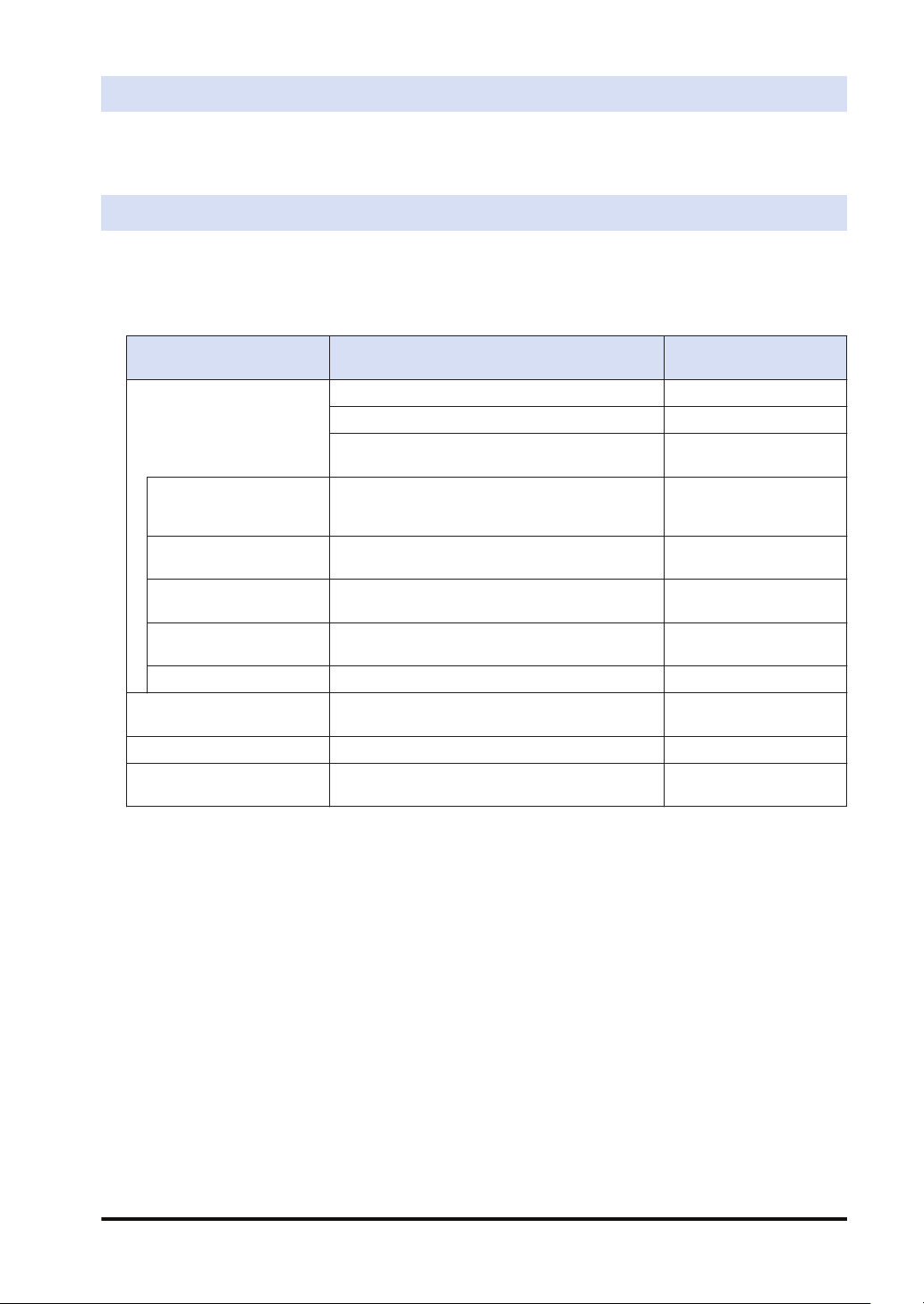
Contents of This Manual
This manual describes the "logging/trace function" and "sampling trace function" implemented
in FP0H Control Unit.
■
Functional comparison
Item Logging/trace function Sampling trace function
Applicable model
iv WUME-FP0HLOG-03
Type with Ethernet function only
AFP0HC32ET/AFP0HC32EP
All FP0H models
Page 5
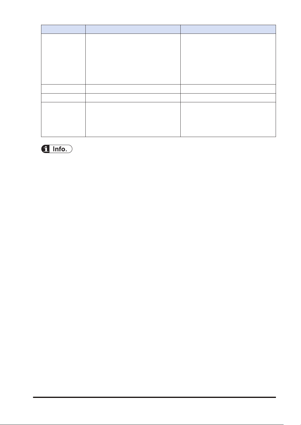
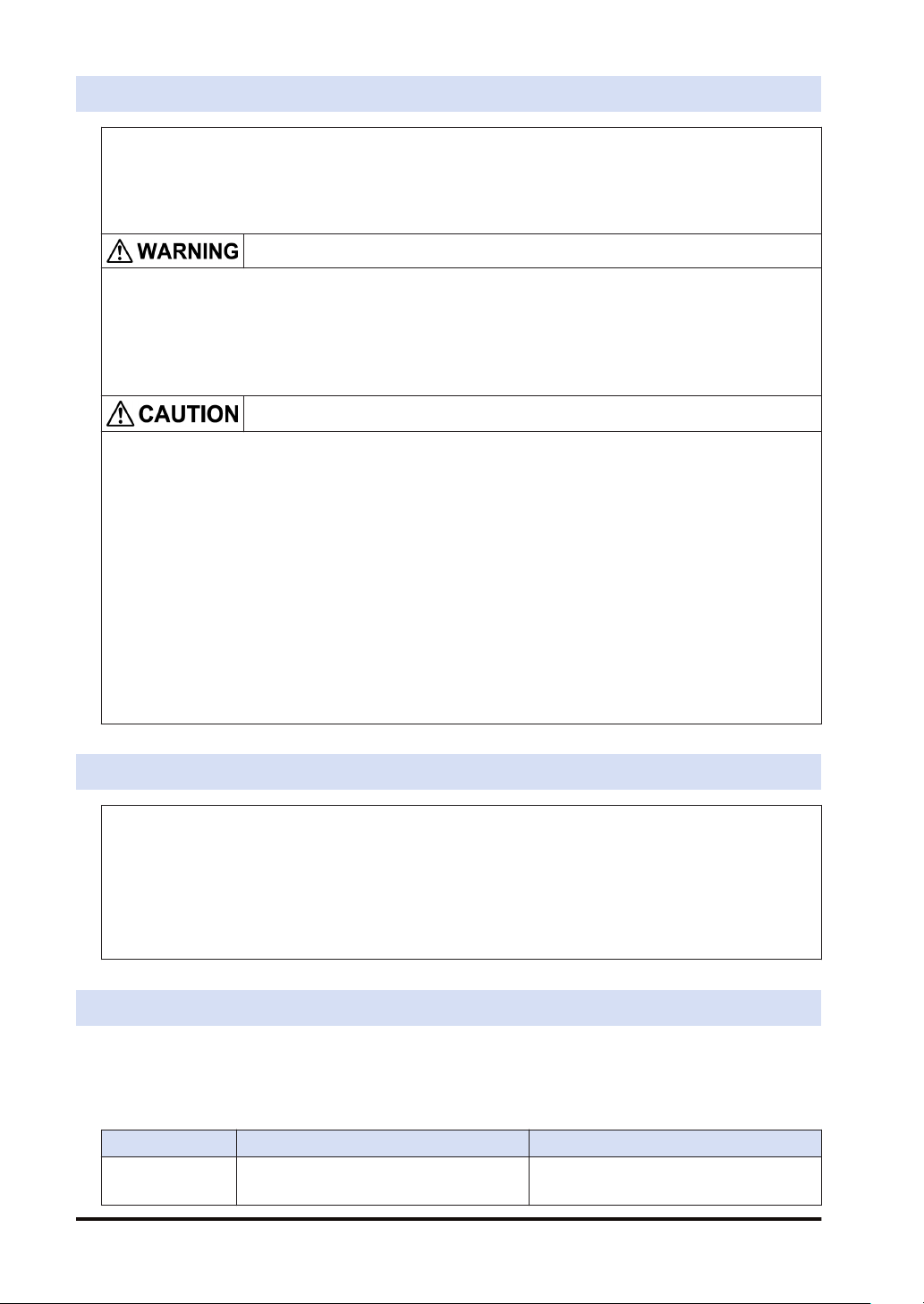
Item Logging/trace function Sampling trace function
Operation information of arbitrary contacts
and data is saved in the buffer memory in
the control unit together with time stamp
Description
No. of devices Max. 128 devices (Max. 256 words) 16 contacts (for 1 word) + 3 words
Memory capacity Max. 64 K words For 1000 samples
Trigger condition
information. With the logging function, they
can also be recorded in an SD memory
card. In comparison with the sampling trace
function, the number of devices that can be
registered and trigger condition has been
extended.
Bit device ON
Cycle: Hour, minute, second
Time: Per minute, Per hour, Every day,
Every week, Every month, Every year
Instruction: F420 (LOGST) instruction
This function can be used by similar
operations to those of the sampling trance
function of existing models FP0R/
FPsigma/FP-X.
Cycle (10 ms to 30 s)
Instruction: F155 (SMPL) instruction
● For details of the logging/trace function, refer to "1 Overview of Logging/Trace Function" to
"6 Logging/Trace Troubleshooting".
● For details of the sampling trace function, refer to "7 Sampling Trace Function".
WUME-FP0HLOG-03 v
Page 6

(MEMO)
vi WUME-FP0HLOG-03
Page 7

Table of Contents
1 Overview of Logging/Trace Function.................................................. 1-1
1.1 For Using Logging/Trace Function......................................................1-2
1.1.1 Applicable model.............................................................................. 1-2
1.1.2 Precautions on Using This Function ................................................ 1-2
1.1.3 Selection of SD Memory Cards........................................................ 1-2
1.2 Overview of Functions ........................................................................1-4
1.2.1 Overview of Logging Function ......................................................... 1-4
1.2.2 Overview of Trace Function ............................................................. 1-5
1.3 Format of Saved Files.........................................................................1-7
1.3.1 File Format (For Logging Function) ................................................. 1-7
1.3.2 File Name (For Logging Function) ................................................... 1-7
1.3.3 File Format (For Trace Function) ..................................................... 1-8
1.3.4 File Name (For Trace Function)....................................................... 1-8
1.4 Data Format........................................................................................1-9
2 Configuration of Logging/Trace Function ..........................................2-1
2.1 Definition of Buffer Memory ................................................................2-2
2.1.1 Setting Method................................................................................. 2-2
2.2 Logging Information Setting................................................................2-3
2.2.1 Confirmation and Settings of File Information.................................. 2-3
2.2.2 LOG File Setting Items (For Logging) .............................................. 2-4
2.3 Trace Information Setting....................................................................2-7
2.3.1 Confirmation and Settings of File Information.................................. 2-7
2.3.2 LOG File Setting Items (For Trace).................................................. 2-8
2.4 Registration of Device Information......................................................2-11
2.5 Operation When Setting Cycle for Logging Trigger ............................2-13
2.6 Downloading Setting Data to Control Unit ..........................................2-15
2.6.1 Downloading to Non-volatile Memory .............................................. 2-15
3 Logging/Trace Start, Stop and Monitor...............................................3-1
3.1 Start and Stop of Logging/Trace Operation ........................................3-2
3.1.1 Start and Stop by Tool Software ...................................................... 3-2
3.1.2 Start and Stop by Instructions.......................................................... 3-3
3.1.3 Automatic Start by Setting ............................................................... 3-3
3.2 Operation Check Using Logging/Trace Monitor..................................3-4
3.2.1 Logging/Trace Monitor ..................................................................... 3-4
3.2.2 Special Internal Relays Relating to Logging/Trace Operation ......... 3-5
3.2.3 Special Data Registers Relating to Logging/Trace Operation.......... 3-6
3.2.4 Checking Logging Speed (When Selecting Logging For
Application) ....................................................................................... 3-6
4 Logging Operation................................................................................4-1
4.1 Flow of Logging Operation..................................................................4-2
4.1.1 Operation Flow................................................................................. 4-2
WUME-FP0HLOG-03
vii
Page 8

4.2 Operation When Logging is Selected for Application .........................4-4
4.2.1 Operation When Logging Operation is Started ................................ 4-4
4.2.2 Operation When Logging Operation Stops ...................................... 4-4
4.2.3 Operation When Power Supply Turns Off........................................ 4-4
4.2.4 Operation When the Battery Cover of Control Unit is Open ............ 4-4
4.2.5 Operation When the Number of Determination Files Reaches the
Maximum Number of Generations.................................................... 4-5
4.3 System Management Information Relating to Logging Function ........4-7
4.3.1 System Management Information and Operation ............................ 4-7
4.3.2 Clearing Management Information................................................... 4-7
5 Trace Operation and Time Chart..........................................................5-1
5.1 Flow of Trace Operation .....................................................................5-2
5.1.1 Flow of Trace Operation................................................................... 5-2
5.2 Operation When Trace is Selected for Application .............................5-4
5.2.1 Operation When Trace Operation is Started.................................... 5-4
5.2.2 Operation When Logging Operation Stops ...................................... 5-4
5.2.3 Operation When Power Supply Turns Off........................................ 5-4
5.2.4 Operation When the Battery Cover of Control Unit is Open ............ 5-4
5.3 Trace Monitor (Time Chart).................................................................5-6
5.3.1 Display Method of Time Chart.......................................................... 5-6
5.3.2 Explanation of Time Chart Monitor................................................... 5-7
5.3.3 Settings for Time Chart Display Area............................................... 5-9
5.3.4 Register Device................................................................................ 5-12
5.3.5 Sampling Condition Setting.............................................................. 5-13
6 Logging/Trace Troubleshooting ..........................................................6-1
6.1 Operations When Errors Occur...........................................................6-2
6.1.1 Operation When Power Supply Turns Off........................................ 6-2
6.1.2 Operation When Errors Occur (Only When Selecting Logging for
Application) ....................................................................................... 6-2
6.1.3 Operations When Inserting/Removing SD Memory Card During
Logging/Trace................................................................................... 6-3
6.2 Troubleshooting ..................................................................................6-4
6.2.1 Errors When Start/Stop Operation was Executed Using FPWIN
GR7................................................................................................... 6-4
6.2.2 Errors When Operation was Executed Using LOGST, LOGED or
LOGSMPL Instruction....................................................................... 6-4
6.2.3 Error of Logging/Trace ..................................................................... 6-5
6.2.4 Error When Copying Data in SD Memory Card ............................... 6-5
7 Sampling Trace Function .....................................................................7-1
7.1 Operation of Sampling Trace Function ...............................................7-2
7.2 Details of Sampling Trace Function....................................................7-3
7.3 How to Use Sampling Trace ...............................................................7-4
7.3.1 Sampling by free run........................................................................ 7-4
7.3.2 Sampling at regular time intervals.................................................... 7-4
7.3.3 Sampling by instruction.................................................................... 7-5
viii
WUME-FP0HLOG-03
Page 9

1 Overview of Logging/Trace
Function
1.1 For Using Logging/Trace Function......................................................1-2
1.1.1 Applicable model.............................................................................. 1-2
1.1.2 Precautions on Using This Function ................................................ 1-2
1.1.3 Selection of SD Memory Cards........................................................ 1-2
1.2 Overview of Functions ........................................................................1-4
1.2.1 Overview of Logging Function ......................................................... 1-4
1.2.2 Overview of Trace Function ............................................................. 1-5
1.3 Format of Saved Files.........................................................................1-7
1.3.1 File Format (For Logging Function) ................................................. 1-7
1.3.2 File Name (For Logging Function) ................................................... 1-7
1.3.3 File Format (For Trace Function) ..................................................... 1-8
1.3.4 File Name (For Trace Function)....................................................... 1-8
1.4 Data Format........................................................................................1-9
WUME-FP0HLOG-03
1-1
Page 10
1.1 For Using Logging/Trace Function
1.1 For Using Logging/Trace Function
1.1.1 Applicable model
The logging/trace function is available for the models of Ethernet type (SD card). However, this
function and the sampling trace function cannot be used concurrently.
■
Applicable models (●: Available, Blank: Not available)
Item
Logging/trace function ●
Sampling trace function ● ●
Ethernet type Non-Ethernet type
C32ET/C32EP C32T/C32P
1.1.2 Precautions on Using This Function
As an SD memory card is used for the logging function, there are risks of loss of data or data
damage depending on usage conditions. Consider possible risks, design a system and make
an evaluation of the system before using the function.
■
Precautions when powering off the PLC
If the PLC is powered off during logging or accessing an SD memory card, the following
problems may occur.
● Data accumulated in the buffer memory are lost.
● Files may be damaged.
● The SD memory card may be damaged.
Take necessary measures such as the use of an uninterruptible power system (UPS) as
necessary.
■
Logging speed and writing speed into an SD memory card
When the speed accumulating data is faster than the writing speed into an SD memory card,
data cannot be saved. Make an evaluation thoroughly before use.
1.1.3 Selection of SD Memory Cards
For the Control Units with the Ethernet function (AFP0HC32ET/AFP0HC32EP), SD memory
cards can be used for copying projects and logging/trace applications. Note the following points
when selecting and using SD memory cards
■
Usable SD memory cards
Please use Panasonic SD memory cards for industrial use.
https://panasonic.net/cns/sdcard/industrial_sd/index.html
(Note): An operation check has not been conducted for SD memory cards made by other
manufacturers.
1-2 WUME-FP0HLOG-03
Page 11
1.1 For Using Logging/Trace Function
Control Unit
printed logo
■
Cautions on handling an SD memory card
Usable SD memory cards
Card type Capacity
SD memory card 2GB
SDHC memory card 4GB to 32GB
The data saved in the SD memory card may be lost in the following cases. We assume no
responsibility whatsoever for the loss of saved data.
● The user or a third party has misused the SD memory card.
● When the SD memory card was affected by any static electricity or electrical noise.
● The SD memory card was taken out, or the PLC body was powered off, while the card was
being accessed.
■
Formatting an SD memory card
In principle, SD memory cards have been formatted by the time of purchase, and no formatting
by the user is required. If formatting becomes necessary, download formatting software for SD
memory cards on the following website.
"Our website (Japanese only)"
https://panasonic.jp/support/sd_w/download/index.html
"SD Association’s website"
https://www.sdcard.org/
● A file system formatted by PC's standard formatting software does not satisfy the SD
memory card specifications. Please use the dedicated formatting software.
● It is recommended to save important data in another media for backup.
● Never remove the card or power off the PLC while accessing the card. Data may be
damaged.
● Do not use an SD memory card the memory capacity of which is more than the usable
capacity. Data in the card may be damaged.
WUME-FP0HLOG-03 1-3
Page 12
1.2 Overview of Functions
1.2 Overview of Functions
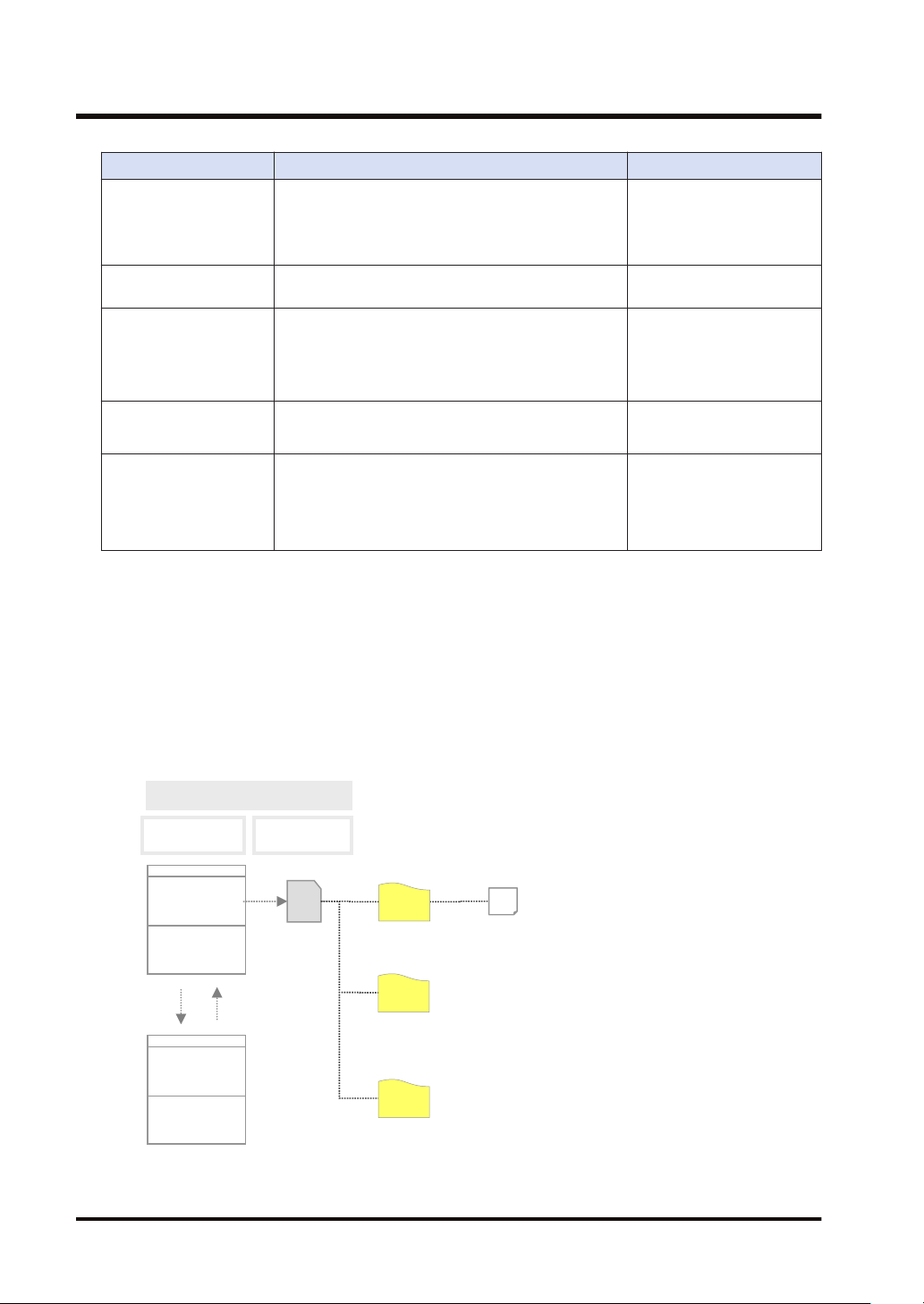
1.2.1 Overview of Logging Function
■
Overview
● The logging function is used to record arbitrary contacts and data information together with
time stamp information at any time, and save them in an SD memory card inserted in the
control unit.
● Log data is saved as CSV format files.
● Use the Logging/Trace Settings menu of tool software to set the conditions.
● The settings are downloaded to the PLC as a part of project data, and stored in the nonvolatile memory.
● The logging operation is executed by any of those operations; (1) tool software, (2) dedicated
instructions or (3) Autostart by the setting.
● To perform data logging at high speed, the buffer memory in the control unit is used.
■
Specifications
Item Specifications Remarks
Max. number of records 60000 records -
Number of file
generations
Number of logs Max. 128 devices (Max. 256 words) per record -
Buffer memory
Logging start-stop
Logging trigger condition
File determination
condition
(Logging stop trigger
condition)
File format Data is saved in CSV format.
(Note 1) Logging is executed when the condition is met at the end of scan.
(Note 2) Use it together with the (DF) instruction to turn ON only for one scan.
Max. 2,000 generations per log -
Max. 64 K words
Can be divided into max. 4 (LOG0 to LOG3) areas for
use.
Capacity per division: 4K words to 64K words
Selectable from the tool software, instructions or
autostart.
Bit device ON
Cycle: Hour, minute, second
Time: Per minute, Per hour, Every day, Every week,
Every month, Every year
Instruction: Executes F420 (LOGST) instruction with
an arbitrary condition and starts logging.
Bit device ON
Time: Per minute, Per hour, Every day, Every week,
Every month, Every year
Max. number of records
(Note 1)
(Note 1)
(Note 1)
(Note 2)
Shared with the trace
function.
-
-
-
Arbitrary comments can be
given.
The upper limit of the
capacity on the file system is
4 GB.
1-4 WUME-FP0HLOG-03
Page 13
PLC
Internal memory
(RAM)
SD
Logging buffer
memory
Log 0
SD memory
card
Log1
Log 3
2
Sample (200724_120100).csv
3
1
X
Sample (200724_120200).csv
Sample (200724_120300).csv
Sample (20xxxxx_xxxxxx).csv
Operation
device
1.2 Overview of Functions
(Note 3) Data stored in the buffer memory will be cleared when the power turns off.
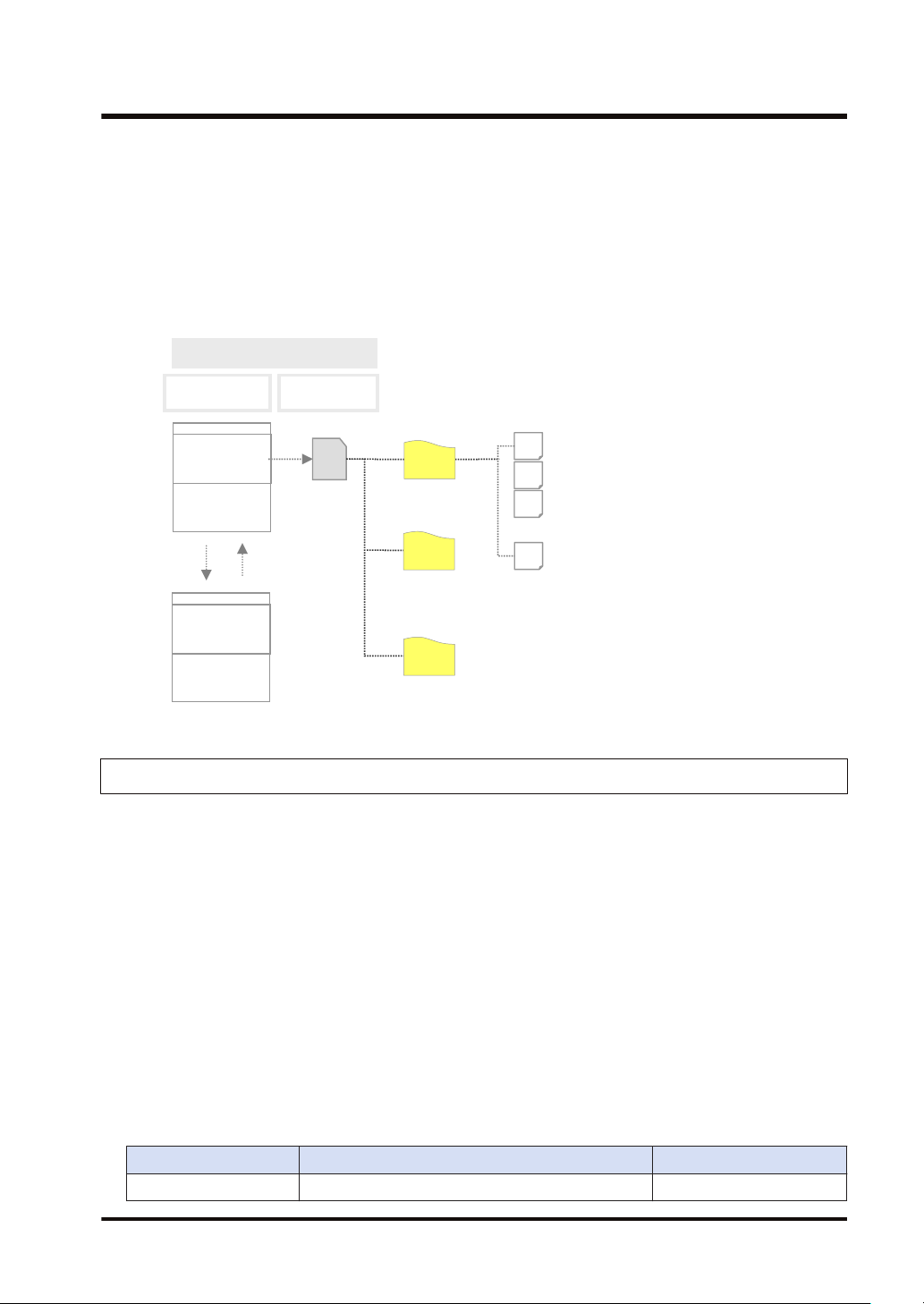
■
Image of logging function
When the set conditions (bit device ON, cycle, time, and instruction) are met, the values of
operation devices will be saved in the logging buffer memory (RAM). The logging operation
continues until the file determination condition is met. Writing data to an SD memory card from
the logging buffer memory is automatically performed by PLC. It is not possible to perform this
operation by users.
1.2.2 Overview of Trace Function
■
● The trace function is used to record arbitrary contacts and data information together with
● Logging data can be uploaded from the buffer memory to the tool software after the trace
● When the trace stop condition is set to bit device, the operation can be stopped after logging
● Use the Logging/Trace Settings menu of tool software to set the conditions.
● The settings are downloaded to the PLC as part of project data, and stored in the non-
● The trace operation is executed by any of those operations; (1) tool software, (2) dedicated
■
WUME-FP0HLOG-03 1-5
Overview
time stamp information in the buffer memory in the control unit at any time.
operation, and can be displayed as a time chart. Traced data can be saved in SD memory
cards as CSV format files.
data of the specified number of samplings after the stop condition has been met.
volatile memory.
instructions or (3) Autostart by the setting.
Specifications
Item Specifications Remarks
Number of logs Max. 128 devices (Max. 256 words) per record -
Page 14
PLC
Internal memory
(RAM)
SD
Logging buffer
memory
Log 0
SD memory
card
Log1
Log 3
Sample (200724_120100_TRACE).csv
1
Operation
device
1.2 Overview of Functions
Item Specifications Remarks
Max. 64 K words
Buffer memory
Can be divided into max. 4 (LOG0 to LOG3) areas for
use.
Capacity per division: 4K words to 64K words
Trace start
Trace trigger condition
Selectable from the tool software, instructions or
autostart.
Bit device ON
Cycle: In msec.
(Note 1)
(Note 1)
Instruction: Executes F420 (LOGST) instruction with
an arbitrary condition and starts tracing.
Trace stop condition
Bit device ON
Buffer full
(Note 2), (Note 3)
File format Data is saved in CSV format.
(Note 1) The trace operation is executed when the condition is met at the end of scan.
(Note 2) When selecting "Bit" for the trace stop condition, logging data of the specified number of samples is
possible after the condition is met.
(Note 3) Unlike the file determination condition of the logging function, logging of data for the specified number
of samples starts when the bit device changes from OFF to ON.
Shared with the logging
function.
-
-
-
Arbitrary comments can be
given.
The upper limit of the
capacity on the file system is
4 GB.
■
● The trace function can also be activated only with the internal memory of the control unit.
● SD memory cards are used only for recording trace data in recording media.
Image of trace function
1-6 WUME-FP0HLOG-03
Page 15
1.3 Format of Saved Files
1.3 Format of Saved Files
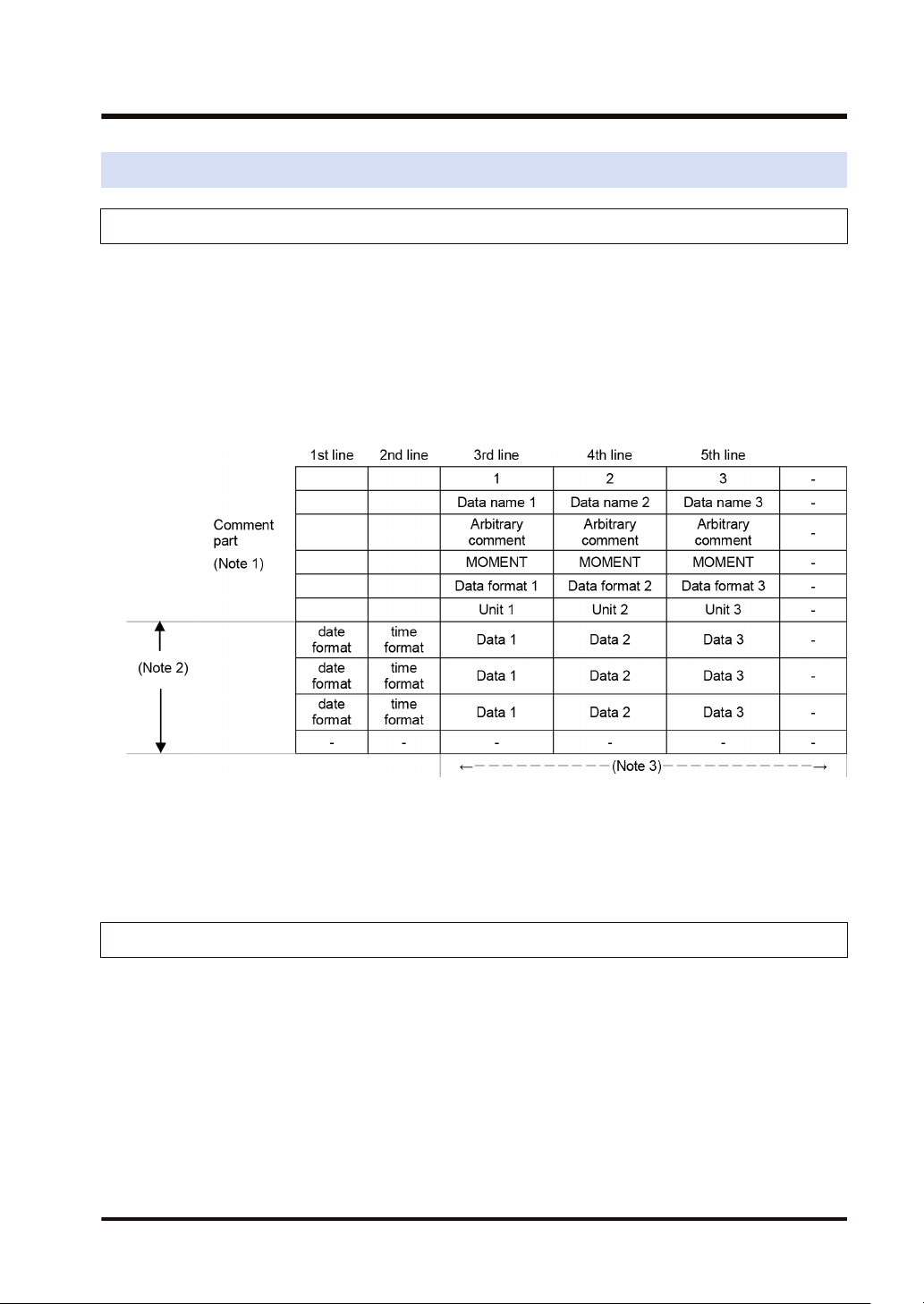
1.3.1 File Format (For Logging Function)
● Files are saved in CSV format.
● For the details of setting methods, refer to "2.2 Logging Information Setting".
■
CSV format
● Time stamp information (year/month/day/hour/minute/second) and information of registered
devices are saved.
● The data length varies depending on the types of specified devices.
● Comments can be given at the beginning of data.
(Note 1) The contents of comment part vary depending on the settings of configuration data.
(Note 2) The number of records varies depending on the settings of file determination condition. Max. 60000
records.
(Note 3) The number of data varies depending on the setting of the number of devices. Max. 128 devices
1.3.2 File Name (For Logging Function)
● A file name to be saved is an arbitrary file name (date_hour-minute-second data of the first
record).
● Enter a desired file name in the “Logging/Trace Settings” dialog box for each LOG number.
Example) When the file name is "Sample", and the time stamp of the first record is 12:00:00 on
July 24, 2020;
Sample(200724_120000).csv
WUME-FP0HLOG-03 1-7
Page 16
1.3 Format of Saved Files
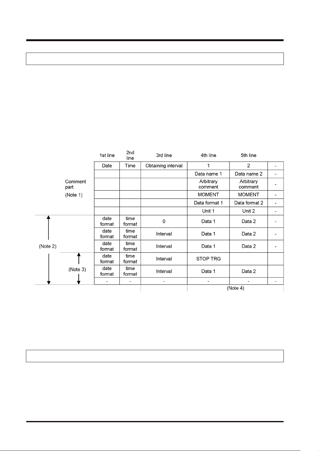
1.3.3 File Format (For Trace Function)
● Files are saved in CSV format.
● For the details of setting methods, refer to "2.3 Trace Information Setting".
■
CSV format
● Time stamp information (year/month/day/hour/minute/second), obtaining interval and
information of registered devices are saved.
● Comments can be given at the beginning of data.
● The unit for the obtaining interval is 10µs. The intervals of obtaining data are saved. The time
from the previous obtainment of data is saved in the line of stop trigger (STOP TRG).
● The data length varies depending on the types of specified devices.
(Note 1) The contents of comment part vary depending on the settings of configuration data.
(Note 2) The number of records varies depending on the settings of file determination condition. Max. 60000
records.
(Note 3) The number of records after the stop trigger varies depending on the settings of configuration data.
(Note 4) The number of data varies depending on the setting of the number of devices. Max. 128 devices
1.3.4 File Name (For Trace Function)
● A file name to be saved is an arbitrary file name (date_hour-minute-second data of the stop
trigger).
● Enter a desired file name in the “Logging/Trace Settings” dialog box for each LOG number.
Example) When the file name is "Sample", and the time stamp of the stop trigger is 12:00:00 on
Friday, July 24, 2020;
Sample(200724_120000_TRACE).csv
1-8 WUME-FP0HLOG-03
Page 17
1.4 Data Format
1.4 Data Format
● The format of the data to be output as logging data and saved in a file varies according to the
type of devices.
● For the details of setting methods, refer to "2.4 Registration of Device Information".
■
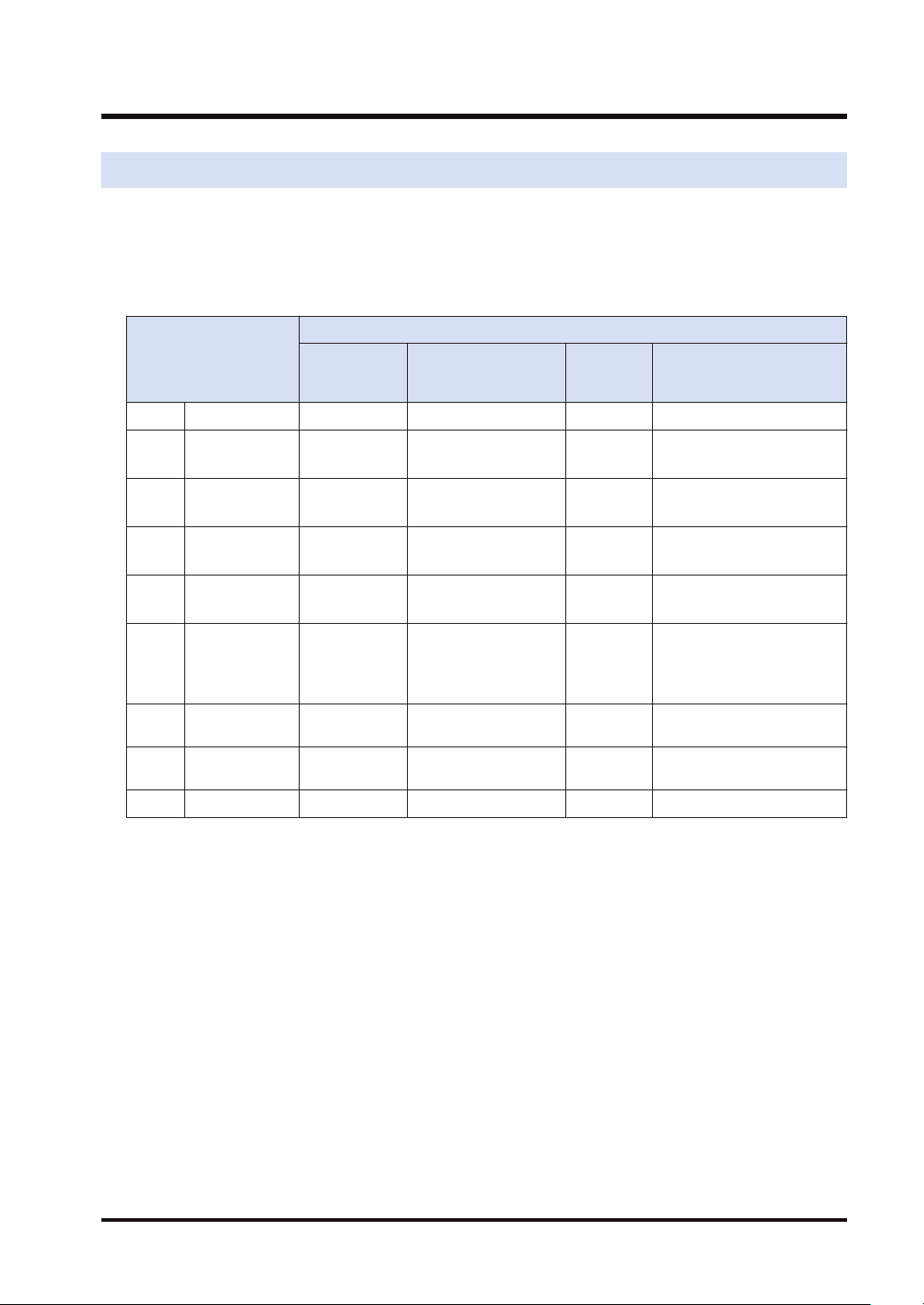
Device type and data format
Output type to files
Data type
BIT Bit data 1 words 0 or 1 1 0 or 1
US
SS
UL
SL
SF
Hex 1 words 1 words
Hex 2 words 2 words
STR String data 1 to 20 bytes Character data 1 to 20 + 2 "ABCD"
(Note 1) Decimal integers (US, SS, UL, SL) and hexadecimal integers (Hex) are output in zero suppression
(Note 2) Decimal integers (US) are output in 5 digits when a specified decimal point output position value is 0,
(Note 3) Decimal integers (SS) are output in 6 digits when a specified decimal point output position value is 0,
(Note 4) Decimal integers (UL) are output in 10 digits when a specified decimal point output position value is 0,
(Note 5) Decimal integers (SL) are output in 11 digits when a specified decimal point output position value is 0,
(Note 6) For a signed integer (SS, SL), a sign is output at the beginning and “+” is replaced with a space.
(Note 7) Zero is added before and after decimal point by the settings of data value and decimal point output
Unsigned
16-bit integer
Signed
16-bit integer
Unsigned
32-bit integer
Signed
32-bit integer
Single-precision
floating
point real
number
format.
in 6 digits when it is 1-4, and in 7 digits when it is 5.
in 7 digits when it is 1-4, and in 8 digits when it is 5.
in 11 digits when it is 1-9, and in 12 digits when it is 10.
in 12 digits when it is 1-9, and in 13 digits when it is 10.
position, and the data is output.
When "Data type" is US and data value is "12345", the output value is "0.12345" when setting
"Decimal point" to 5.
When "Data type" is US and data value is "123", the output value is "0.00123" when setting "Decimal
point" to 5.
No. of
occupied
words
1 words
1 words
2 words
2 words
2 words
Data type
Decimal integer
(unsigned)
Decimal integer
(signed)
Decimal integer
(unsigned)
Decimal integer
(signed)
Decimal or exponential
form
(auto)
Hexadecimal integer
(unsigned)
Hexadecimal integer
(unsigned)
No. of
characters
5 0 to 65536
6 -32768 to 32767
10 0 to 4294967295
11
13 -1.175494E-38
4 0 to FFFF
8 0 to FFFF FFFF
Range or sample
-2147483648
to 2147483647
WUME-FP0HLOG-03 1-9
Page 18

1.4 Data Format
(Note 8) Double quotation marks “ “ are added before and after character string data.
1-10 WUME-FP0HLOG-03
Page 19

2 Configuration of Logging/
Trace Function
2.1 Definition of Buffer Memory ................................................................2-2
2.1.1 Setting Method................................................................................. 2-2
2.2 Logging Information Setting................................................................2-3
2.2.1 Confirmation and Settings of File Information.................................. 2-3
2.2.2 LOG File Setting Items (For Logging) .............................................. 2-4
2.3 Trace Information Setting....................................................................2-7
2.3.1 Confirmation and Settings of File Information.................................. 2-7
2.3.2 LOG File Setting Items (For Trace).................................................. 2-8
2.4 Registration of Device Information......................................................2-11
2.5 Operation When Setting Cycle for Logging Trigger ............................2-13
2.6 Downloading Setting Data to Control Unit ..........................................2-15
2.6.1 Downloading to Non-volatile Memory .............................................. 2-15
WUME-FP0HLOG-03
2-1
Page 20
2.1 Definition of Buffer Memory
2.1 Definition of Buffer Memory
2.1.1 Setting Method
Setting method
● Define the buffer memory of the control unit used for the logging/trace function.
● The buffer memory is set with the tool software FPWIN GR7.
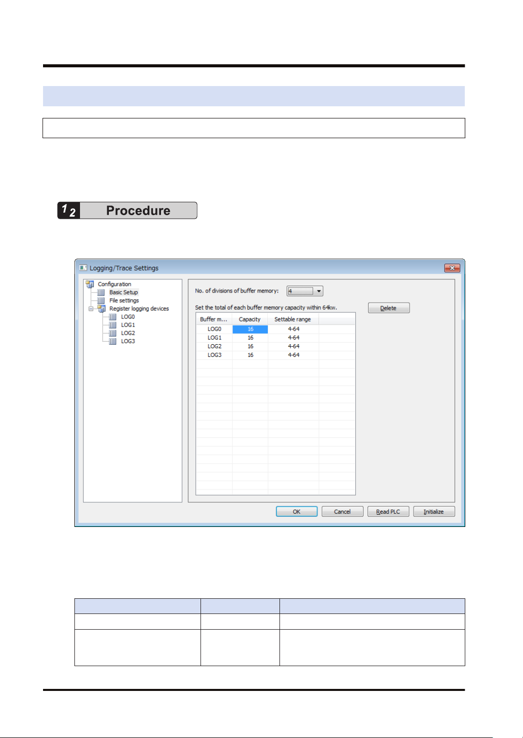
1. Select "Tool">"Logging/Trace Settings" in the menu bar.
The “Logging/Trace Settings” dialog box appears.
2. Select "No. of divisions of buffer memory" from the range of 1 to 4.
3. Double-click on the field of Capacity, and input a desired capacity.
Capacity is allocated to each buffer memory.
Setting range
Item Default Setting range
No. of divisions of buffer memory 4 1-4
LOG0-LOG3
Buffer memory capacity (unit: k
word)
2-2 WUME-FP0HLOG-03
16 4-64
Page 21
2.2 Logging Information Setting
2.2 Logging Information Setting
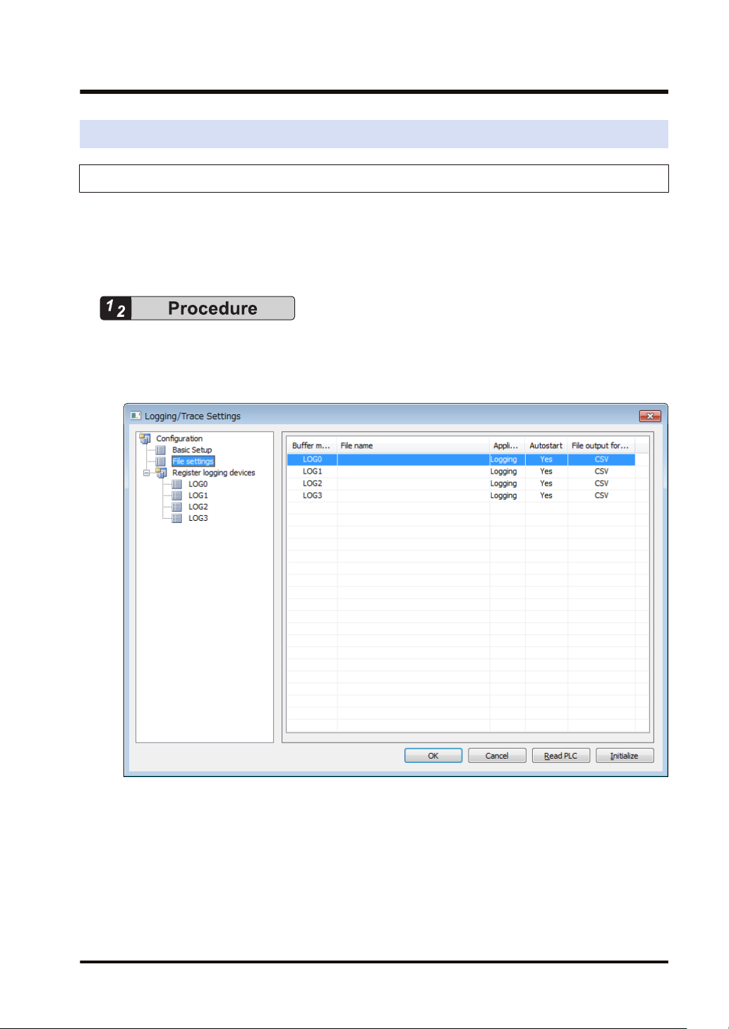
2.2.1 Confirmation and Settings of File Information
Overview
● After completing the definition of buffer memory, set the data to be logged and the format of
saved files.
● File formats and logged device data are set for each buffer memory (LOG0 to LOG3).
1. Select "Tool">"Logging/Trace Settings" in the menu bar.
The “Logging/Trace Settings” dialog box appears.
2. Select "File settings" from the list on the left.
3. Double-click a desired buffer memory from the list on the right.
The LOG0 to LOG3 file settings dialog box appears.
WUME-FP0HLOG-03 2-3
Page 22
2.2 Logging Information Setting
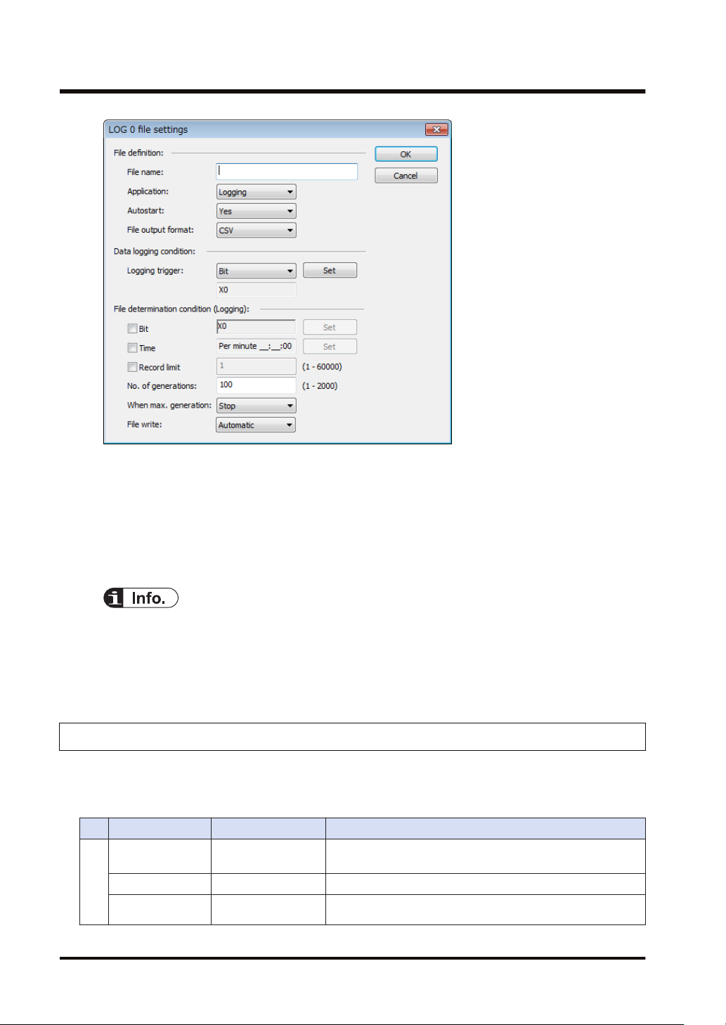
LOG file settings dialog box
4. Set information in each field of File definition, Data logging condition and File determination
condition.
For the details of setting methods, refer to "2.2.2 LOG File Setting Items (For Logging)".
5. Press the [OK] button.
This returns to the Logging/Trace Settings dialog box.
● More than one file determination condition can be set for logging application.
● Even when active logging stops, a file is determined.
● For the bit device of file determination condition, select a bit which turns on for only one
scan at the end of scan.
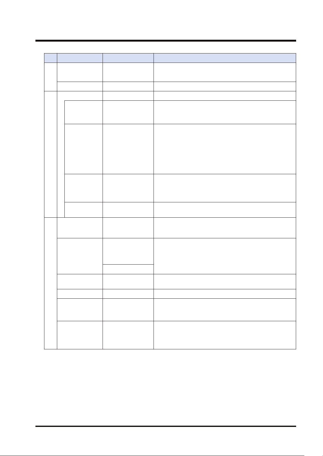
2.2.2 LOG File Setting Items (For Logging)
The following items are set in the LOG file settings dialog box.
■
Setting item
Item Setting range Settings
File name
Application Logging Select Logging.
Autostart Yes / No
File definition
Within 32 one-byte
characters
Enter a file name to be saved in a selected LOG number.
Yes: Logging operation starts when changing to the RUN
mode.
2-4 WUME-FP0HLOG-03
Page 23
2.2 Logging Information Setting
Item Setting range Settings
No: Logging operation is started or stopped by the operation
of programming tool or the F420(LOGST) instruction/
F421(LOGED) instruction in user programs.
File output format CSV Select CSV.
Logging trigger Select a condition to start logging data.
Select this for setting bit conditions as logging trigger. Press
the [Set] button, and select a device type and a number.
1)
Bit
Specify an arbitrary
bit device.
(Note
Select this for setting time as logging trigger. Input a cycle for
executing logging.
(Note 2)
1 second, 2 seconds, 3 seconds, 4 seconds, 5 seconds, 6
Cycle Time data
seconds, 10 seconds, 15 seconds, 30 seconds,
1 minute, 2 minutes, 3 minutes, 4 minutes 5 minutes, 6
minutes, 10 minutes, 15 minutes, 30 minutes,
1 hour, 2 hours, 3 hours, 4 hours, 6 hours, 12 hours, 24 hours
Data logging condition
Time Clock data
Select this for setting clock time as logging trigger. Specify the
time for starting logging.
Per minute, Per hour, Every day, Every week, Every month,
Every year
Instruction -
Bit
Specify an arbitrary
bit device.
Trigger conditions occur by executing the F422(LOGSMPL)
instruction under arbitrary conditions in user programs.
Select this for setting bit conditions as file determination
condition. Press the [Set] button, and select a device type and
a number.
Per minute, Per
Time
hour, Every day,
Every week, Every
month, Every year
Select this for setting a fixed time as file determination
condition. Specify a time for determining files.
Clock data
Record limit 1 to 60000
Select this for setting the number of records as file
determination condition. Specify the upper limit.
No. of generations 1 to 2000 Set the number of files (generations) to be saved in folder.
When max.
File determination condition
generation
Stop, Continue
Stop: Stops logging.
Continue: Determines a file, and deletes the oldest file in the
PLC. After that, creates a new file.
Automatic: Once a file is determined, executes writing it into
File write
Automatic, 1 record
unit
an SD memory card.
1 record unit: Writes data to a file every time one record is
written.
(Note 1) For the bit device of file determination condition, select a bit which turns on for only one scan at the
end of scan.
(Note 2) When the logging trigger is cycle and setting per second or per minute, adjust to occur a trigger at 0
min. 0 sec. of every hour. When the unit of cycle is time, adjust to occur a trigger at 00:00:00 of every
day. For details, refer to "2.5 Operation When Setting Cycle for Logging Trigger".
■
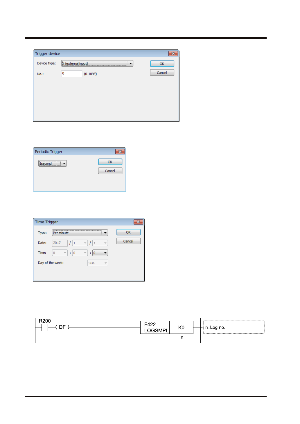
"Logging trigger" - "Trigger device" setting dialog box
● Set this for using bit device for the condition to start logging.
WUME-FP0HLOG-03 2-5
Page 24
2.2 Logging Information Setting
■
"Logging trigger" - "Periodic Trigger" setting dialog box
● Set this for performing logging periodically.
■
"Logging trigger" - "Time Trigger" setting dialog box
● Set this for performing logging at fixed intervals.
■
"Logging trigger" - Trigger condition setting with F422 (LOGSMPL) instruction
● Specify a logging number with the dedicated instruction, and execute with an arbitrary
condition.
2-6 WUME-FP0HLOG-03
Page 25

2.3 Trace Information Setting
2.3 Trace Information Setting
2.3.1 Confirmation and Settings of File Information
● The following items are set in the LOG file settings dialog box.
Overview
● After completing the definition of buffer memory, set the data to be traced and the format of
saved files.
● File formats and traced device data are set for each buffer memory (LOG0 to LOG3).
1. Select Tool>Logging/Trace Settings in the menu bar.
The “Logging/Trace Settings” dialog box appears.
2. Select "File settings" from the list on the left.
3. Double-click a desired buffer memory from the list on the right.
The LOG0 to LOG3 file settings dialog box appears.
WUME-FP0HLOG-03 2-7
Page 26

2.3 Trace Information Setting
4. Set information in each field of File definition, Data logging condition and Trace stop.
For the details of setting methods, refer to "2.3.2 LOG File Setting Items (For Trace)".
5. Press the [OK] button.
This returns to the Logging/Trace Settings dialog box.
● ”No. of samplings after stop trigger” is available only when the stop trigger is set to Bit.
● Check the box of [Write file after completion of trace] to create a file in a SD memory card
after the completion of trace.
2.3.2 LOG File Setting Items (For Trace)
● The following items are set in the LOG file settings dialog box.
■
Setting item
Item Setting range Settings
File name Within 32 characters Enter a file name to be saved in a selected LOG number.
Application Trace Select Trace.
Yes: Trace operation starts when changing to the RUN mode.
Autostart Yes / No
File definition
File output format CSV Select CSV.
No: Trace operation is started by the operation of
programming tool or the LOGST instruction in user programs.
2-8 WUME-FP0HLOG-03
Page 27

2.3 Trace Information Setting
Item Setting range Settings
Logging trigger Select a condition to start logging data.
Bit
Cycle Time data
Data logging condition
Instruction -
Stop trigger
No. of samplings
after stop trigger
detection
Trace stop condition
File write Auto
Specify an arbitrary
bit device.
Bit
Buffer full Trace operation stops once the buffer is full.
0 to 65536
Select this for setting bit conditions as logging trigger. Press
the [Set] button, and select a device type and a number.
Select this for setting time as logging trigger. Input a cycle for
executing trace.
1 second, 2 seconds, 3 seconds, 4 seconds, 5 seconds, 6
seconds, 10 seconds, 15 seconds, 30 seconds,
1 minute, 2 minutes, 3 minutes, 4 minutes 5 minutes, 6
minutes, 10 minutes, 15 minutes, 30 minutes,
1 hour, 2 hours, 3 hours, 4 hours, 6 hours, 12 hours, 24 hours
Specify in msec: 1 to 1000
Trigger conditions occur by executing the F422(LOGSMPL)
instruction under arbitrary conditions in user programs.
Stops Trace.
Press the [Set] button to specify a device type, a number and
the number of samplings after the detection of stop trigger.
Specify the number of samplings after the detection of stop
trigger.
On completion of trace operation, executes writing data into
an SD memory card.
■
"Logging trigger" - "Trigger device" setting dialog box
Set this for using bit device for the condition to start tracing.
■
"Logging trigger" - "Periodic Trigger" setting dialog box
Set this for performing tracing periodically. When selecting Trace for Application, it can be
specified in msec.
WUME-FP0HLOG-03 2-9
Page 28

2.3 Trace Information Setting
■
"Logging trigger" - Trigger condition setting with F422(LOGSMPL) instruction
Specify a logging number with the dedicated instruction, and execute with an arbitrary
condition.
2-10 WUME-FP0HLOG-03
Page 29

2.4 Registration of Device Information
2.4 Registration of Device Information
Overview
● Devices on which logging/trace is performed are registered in "Register logging devices".
1. Select a desired LOG number of Register logging devices from the list on the left side.
2. Double-click a desired buffer memory from the list on the right.
The “Register devices” dialog box appears.
3. Enter a desired device number and comments, and press the [OK] button.
The device on which logging is performed is registered in the LOG number.
WUME-FP0HLOG-03 2-11
Page 30

2.4 Registration of Device Information
4. Repeat the registration of devices for each LOG number.
● The number of devices that can be registered in one LOG number is up to 128 devices.
● Press the <INS> key to insert items in the device list, and press the <DEL> key to delete
them.
Setting items (”Register devices” dialog box)
Item Setting range Settings
X, Y, R, L, T, C
Device type
No. Device no. Specify a device number to be logged.
Data type
Decimal point 0 to 11
No. of continuous
registrations
Data name Within 16 characters
Arbitrary
application
Unit Within 8 characters
Register comment
WX, WY, WR, WL, DT, LD, I,
SV, EV
Bit data
Unsigned 16-bit integer
Signed 16-bit integer
Unsigned 32-bit integer
Signed 32-bit integer
Single-precision real
HEX (1 word)
HEX (2 words)
String
1 to max. 128
Within 8 characters
Specify a device type to be logged.
Specify a data format to be output. The settable
range varies according to the number of selected
devices.
The position of decimal point can be set when an
integer type is selected for Data type. The settable
range varies according to the selected data type.
Input a number for specifying the same type of
devices all at once. The settable range varies
according to the number of selected devices.
Output to the comment area when saving data in
CSV format.
2-12 WUME-FP0HLOG-03
Page 31

2.5 Operation When Setting Cycle for Logging Trigger
2.5 Operation When Setting Cycle for Logging Trigger
When setting Cycle for logging triggers, the time of the first trigger is adjusted to perform
subsequent logging at good timing.
● When the unit of cycle is second or minute, adjust to occur a trigger at 0 min. 0 sec. of every
hour.
● When the unit of cycle is time, adjust to occur a trigger at 00:00:00 of every day.
■
Example of timing of trigger occurrence (when the unit of cycle is second)
Time at which
logging
trigger condition is
met
12:01:05 1
12:01:05 2
12:01:05 3
12:01:05 4
12:01:05 5
12:01:05 10
12:01:05 15
12:01:05 30
Set
cycle
seconds
seconds
seconds
seconds
seconds
seconds
seconds
seconds
Time at which the 1st trigger
occurs after adjustment
12:01:06 12:01:07, 12:01:08
12:01:06 12:01:08, 12:01:10
12:01:06 12:01:09, 12:01:12
12:01:08 12:01:12, 12:01:16
12:01:10 12:01:15, 12:01:20
12:01:10 12:01:20, 12:01:30
12:01:15 12:01:30, 12:01:45
12:01:30 12:02:00, 12:02:30
Time at which subsequent triggers
occur
■
Example of timing of trigger occurrence (when the unit of cycle is minute)
Time at which
logging
trigger condition is
met
12:01:00 1
12:03:00 2
12:05:00 3
12:05:00 4
12:05:00 5
12:01:00 10
Set
cycle
minutes
minutes
minutes
minutes
minutes
minutes
Time at which the 1st trigger
occurs after adjustment
12:02:00 12:03, 12:04, 12:05
12:04:00 12:04, 12:06, 12:08
12:06:00 12:09, 12:12, 12:15
12:08:00 12:12, 12:16, 12:20
12:10:00 12:15, 12:20, 12:25
12:10:00 12:20, 12:30, 12:40
Time at which subsequent triggers
occur
WUME-FP0HLOG-03 2-13
Page 32

2.5 Operation When Setting Cycle for Logging Trigger
Time at which
logging
trigger condition is
met
12:59:00 15
12:10:00 30
■
Example of timing of trigger occurrence (when the unit of cycle is hour)
Time at which
logging
trigger condition is
met
12:59:00 1 hours 13:00:00 14, 15, 16 o’clock ...
12:59:00 2 hours 14:00:00 16, 18, 20 o’clock ...
12:30:00 3 hours 15:00:00 18, 21, 24 o’clock ...
12:30:00 4 hours 16:00:00 20, 24, 28 o’clock ...
12:30:00 6 hours 18:00:00 24, 30, 36 o’clock ...
12:30:00 12 hours 24:00:00 36, 48, 60 o’clock ...
12:30:00 24 hours 24:00:00 48, 72, 96 o’clock ...
Set
cycle
minutes
minutes
Set
cycle
Time at which the 1st trigger
occurs after adjustment
13:00:00 13:15, 13:30, 13:45
12:30:00 13:00, 13:30, 14:00
Time at which the 1st trigger
occurs after adjustment
Time at which subsequent triggers
occur
Time at which subsequent triggers
occur
2-14 WUME-FP0HLOG-03
Page 33

2.6 Downloading Setting Data to Control Unit
2.6 Downloading Setting Data to Control Unit
2.6.1 Downloading to Non-volatile Memory
■
Overview
Parameters set in the logging/trace settings menu are downloaded together with programs and
configuration data as project data.
WUME-FP0HLOG-03 2-15
Page 34

(MEMO)
2-16 WUME-FP0HLOG-03
Page 35

3 Logging/Trace Start, Stop
and Monitor
3.1 Start and Stop of Logging/Trace Operation ........................................3-2
3.1.1 Start and Stop by Tool Software ...................................................... 3-2
3.1.2 Start and Stop by Instructions.......................................................... 3-3
3.1.3 Automatic Start by Setting ............................................................... 3-3
3.2 Operation Check Using Logging/Trace Monitor..................................3-4
3.2.1 Logging/Trace Monitor ..................................................................... 3-4
3.2.2 Special Internal Relays Relating to Logging/Trace Operation ......... 3-5
3.2.3 Special Data Registers Relating to Logging/Trace Operation.......... 3-6
3.2.4 Checking Logging Speed (When Selecting Logging For
Application) ....................................................................................... 3-6
WUME-FP0HLOG-03 3-1
Page 36

3.1 Start and Stop of Logging/Trace Operation
3.1 Start and Stop of Logging/Trace Operation
3.1.1 Start and Stop by Tool Software
Overview
The logging/trace operation can be started and stopped by the tool software.
1.
Select "Tool">"Logging/Trace Monitor" in the menu bar.
The "Logging/Trace Monitor" dialog box appears.
2. Check the box of a desired LOG number, and press the [Start] button.
A confirmation message appears.
3. Press the [Yes] button.
Starting the logging operation is requested by the operation specified in the “Logging/Trace
Settings” dialog box. System relays relating to the execution of logging/trace can be
monitored in the above dialog box. Once the operation is started normally, the "Logging/
Trace is being executed" and "SD logging is being executed" flags turn on.
4. For stopping the logging/trace operation, check the box of a desired LOG number and
press the [Stop] button.
Stopping the logging/trace operation is requested. Once the logging/trace operation ends
normally, the "Logging/trace is complete" flag turns on.
3-2 WUME-FP0HLOG-03
Page 37

3.1 Start and Stop of Logging/Trace Operation
3.1.2 Start and Stop by Instructions
■
Overview
● The logging/trace operation can be started and stopped by user programs for each logging/
trace number.
● Specify a logging/trace number (0 to 3) using the dedicated instruction, and execute with
arbitrary conditions.
● It takes a few milliseconds to a few seconds to start or stop the logging/trace operation.
● For stopping the logging/trace operation with instructions, request the stop after confirming
that the execution active flag (R9180/R9190/R9200/R9210) turns on. If requesting to stop
LOG n during the start operation, the operation error flag (R9007/R9008) or the logging/trace
error flag (R9185/R91915/R9205/R9215) turns on.
● For starting the logging/trace operation with instructions, request the start after confirming
that the logging/trace completed flag (R9182/R9192/R9202/R9212) turns on. If requesting to
stop LOG n during the start operation, the operation error flag (R9007/R9008) or the logging/
trace error flag (R9185/R9195/R9205/R9215) turns on.
● There is no problem if a start request is made for LOG n that is activated or during the
startup operation.
● There is no problem if a stop request is made for LOG n that is stopped or during the stop
operation.
3.1.3 Automatic Start by Setting
● When "Autostart" has been selected in the "LOG file settings" dialog box, the start request of
the logging/trace operation is made immediately after the mode is switched to RUN mode.
● The trace operation stops when the trace stop condition (bit device ON or buffer full) is
met. If the operation is forcibly stopped with the tool software or instruction while the trace
stop condition has not been satisfied, the trace operation is canceled and the data is not
saved.
WUME-FP0HLOG-03 3-3
Page 38

3.2 Operation Check Using Logging/Trace Monitor
3.2 Operation Check Using Logging/Trace Monitor
3.2.1 Logging/Trace Monitor
The progress situation can be confirmed with the logging/trace monitor.
■
Example of monitoring in logging operation
■
Example of monitoring on the completion of trace operation
3-4 WUME-FP0HLOG-03
Page 39

3.2 Operation Check Using Logging/Trace Monitor
3.2.2 Special Internal Relays Relating to Logging/Trace Operation
■
Special Internal Relay
Device
no.
Name Operation
Turns on while the logging/trace function is activated. Another system relay
allocated to the same LOG number is reset during the start operation.
The logging/trace function is activated by any of the following methods; 1:
Autostart, 2: Start by instruction, 3: Start by tool software. Storing data in the
R9180
Logging/trace is
being executed.
buffer memory is executed while this relay is on.
R9181
R9182
Logging/trace
buffer storage/File
being written
Logging/trace
completed
Turns on when writing files into an SD memory card becomes enabled after
turning on the logging/trace active relay and enabling the logging in the
buffer. This relay is always off when selecting Trace for the application.
Turns on after the completion of file writing when requesting to stop the
logging trace operation or performing the automatic stop.
Turns on when the buffer logging speed exceeds the writing speed to an SD
memory card in the logging processing. Turns on when the number of data
previously stored and the number of data stored this time increase.
Turns on at the timing of buffer logging, and turns off at the timing of buffer
R9183
Logging overspeed relay
logging or the end of scan.
Turns on when the buffer memory has been exhausted. The buffer overflow
counter (DT90620) is incremented by one. At that time, new data cannot be
stored. Also, writing data into the SD memory card does not stop.
The buffer overflow relay turns off at the end of scan when a vacancy occurs
R9184 Buffer overflow
in the buffer as writing data into an SD memory card progresses, and the
buffer overflow counter is cleared to 0. Also, after the occurrence of vacancy
in the buffer, data logging is executed once the logging trigger condition is
met.
This relay is always on when buffer full occurs as the stop condition when
selecting Trace for the application.
R9185 Logging/trace error
Turns on when an error is detected during the logging/trace operation and
stops the operation.
Turns on when one of the following conditions is met during the logging/trace
R9186
No SD card free
space
operation and stops the logging/trace operation.
When an SD memory card is running out of free space
When an error in accessing an SD memory card occurs.
Turns on when an error is detected in setting values during the startup
R9187
Device/trigger
setting error
operation. The logging/trace error relay R9185 also turns on. At that time,
the active relay does not turn on because the logging/trace function cannot
be activated.
R9188
Trace stop trigger
monitor
Trace data
R9189
acquisition
completed
(Note 1) The above device numbers are those for LOG0. Special internal relay numbers vary depending on
LOG numbers as shown in the table below.
Monitors a registered trace stop trigger when executing tracing. Turns on
when the condition is met. This relay is always off when selecting Logging
for the application.
Turns on after logging data for a specified number of times after detecting
the trace stop trigger during the execution of trace. This relay is always off
when selecting Logging for the application.
LOG no. 0 1 2 3
Relay no. R9180 to R9189 R9190 to R9199 R9200 to R9209 R9210 to R9219
WUME-FP0HLOG-03 3-5
Page 40

3.2 Operation Check Using Logging/Trace Monitor
3.2.3 Special Data Registers Relating to Logging/Trace Operation
■
Special data registers
Device
no.
DT90600 Buffer free space
DT90620
DT90640
DT90660
DT90680
-DT90681
(Note 1) The above device numbers are those for LOG0. Special data register numbers vary depending on
LOG no. 0 1 2 3
Buffer free space DT90600 DT90601 DT90602 DT90603
Buffer overflow counter DT90620 DT90621 DT90622 DT90623
No. of written records of current file DT90640 DT90641 DT90642 DT90643
No of files (generations) stored in folder DT90660 DT90661 DT90662 DT90663
Oldest clock data of file stored in folder DT90680
Name Operation
Stores free space of buffer memory during logging. This is always
zero when selecting Trace for the application.
Buffer overflow
counter
No. of written records of
current file
No of files (generations)
stored in folder
Oldest clock data of file
stored in folder
LOG numbers as shown in the table below.
Increments the value by one when the buffer overflow occurs. This is
always zero when selecting Trace for the application.
Stores the number of written records in a current file as 16-bit data.
Increments the number by one every time data is written in the
current file. It is reset to zero when a new file is created.
Stores the number of files stored in a folder (number of generations)
as 16-bit data.
Stores the oldest clock data of a file stored in a folder as 32-bit data
in seconds. The clock data is the number of seconds accumulated
from 00:00:00 on January 1, 2001.
-DT90681
DT90682
-DT90683
DT90684
-DT90685
DT90686
-DT90687
3.2.4 Checking Logging Speed (When Selecting Logging For Application)
● When the logging speed to the buffer memory of the control unit is faster than the writing
speed into an SD memory card, the logging over-speed relay turns on. The logging overspeed relay turns on at the timing of logging trigger, and turns off if the speed does not
exceed at the end of scan.
● If overspeed occurs frequently, the buffer memory will be full and data cannot be
accumulated.
● Once the buffer memory is full, the buffer overflow flag turns on, and the buffer overflow
counter is incremented by one.
● If the buffer overflow occurs continuously, revise the logging conditions to decrease the
logging speed.
● To know how much logging data was lost at the time of buffer overflow, register the buffer
overflow counter as logging data.
● Even if the buffer overflow occurs, recording data into an SD memory card goes on, and
logging continues when free space becomes available in the buffer.
3-6 WUME-FP0HLOG-03
Page 41

3.2 Operation Check Using Logging/Trace Monitor
● The free space of buffer memory can be checked with the system data registers DT90600 to
DT90603.
● The system relays (R9184/R9194/R9204/R9214) give a warning when the buffer memory of
each LOG number is full.
WUME-FP0HLOG-03 3-7
Page 42

(MEMO)
3-8 WUME-FP0HLOG-03
Page 43

4 Logging Operation
4.1 Flow of Logging Operation..................................................................4-2
4.1.1 Operation Flow................................................................................. 4-2
4.2 Operation When Logging is Selected for Application .........................4-4
4.2.1 Operation When Logging Operation is Started ................................ 4-4
4.2.2 Operation When Logging Operation Stops ...................................... 4-4
4.2.3 Operation When Power Supply Turns Off........................................ 4-4
4.2.4 Operation When the Battery Cover of Control Unit is Open ............ 4-4
4.2.5 Operation When the Number of Determination Files Reaches the
Maximum Number of Generations.................................................... 4-5
4.3 System Management Information Relating to Logging Function ........4-7
4.3.1 System Management Information and Operation ............................ 4-7
4.3.2 Clearing Management Information................................................... 4-7
WUME-FP0HLOG-03
4-1
Page 44

4.1 Flow of Logging Operation
4.1 Flow of Logging Operation
4.1.1 Operation Flow
■
Triggers of logging operation and file contents
Step OperationTrigger of operation File in LOG folder File contents
● Tool software
(1) Start
(2) Logging
File
(3)
determin
ation
(2) Logging
File
(3)
determin
ation
Logging, file determination, and logging operation continues until the stop condition is met.
(4) Stop
(Note 1) "Logging in the logging buffer (RAM)" and "writing to an SD memory card from the logging buffer" are
controlled on the system side. They cannot be controlled by user programs.
operation
● Instruction
● Auto start by setting
● Bit device ON
● Cycle
● Instruction
Sample(------current------).csv”
Comment file part
First record
● Time
● Bit device ON
● Cycle
● Instruction
● Time
Sample(------current------).csv”
Comment file part
First record
Second record
Logging operation continues until the file determination condition is met.
● Bit device ON
● Time
● Record limit
● Bit device ON
● Cycle
● Instruction
● Time
Sample(130401_120000).csv”
Sample(------current------).csv” Comment file part
Sample(130401_120000).csv”
Sample(------current------).csv”
Comment file part
Records up to file
determination
Comment file part
Records up to file
determination
Comment file part
First record
Logging operation continues until the file determination condition is met.
● Bit device ON
● Time
● Record limit
● Tool software
operation
● Instruction
● Max. generation
Sample(130401_120000).csv”
Sample(130401_130000).csv”
Sample(------current------).csv” Comment file part
Sample(130401_120000).csv”
Sample(130401_130000).csv”
Sample(130401_140000).csv”
Comment file part
Records up to file
determination
(Note 1)
Comment file part
Records up to file
determination
Comment file part
Records up to stop
(Note 1)
(Note 1)
4-2 WUME-FP0HLOG-03
Page 45

4.1 Flow of Logging Operation
■
Flow of Logging Operation
Step (1) Startup of logging operation
● The logging operation is started by any of the following methods; Tool software operation,
Instruction in a user program, and Autostart setting.
Step (2)-a: Data logging into logging buffer memory (RAM)
● After the startup of logging operation, logging data is executed with a specified condition
once the specified trigger condition (bit device ON, cycle, or time) is met.
● Logged data is stored once in the logging buffer memory (RAM) of the control unit.
Step (2)-b: Data transfer to SD memory card from logging buffer memory (RAM)
● Data is stored in the logging buffer memory (RAM) sequentially, and automatically written to
a file in an SD memory card by the control unit. It cannot be controlled by user programs.
● A LOG folder is created in an SD memory card for the LOG number that a file name is set.
● A file "specified file name (------current------).csv" for saving logging data is created in the
LOG folder.
● After that, the control unit continues saving data into the same file until the file determination
condition is met.
Step (3): Determination of file
● The file is determined when the specified file determination condition (bit device ON, time,
record limit) is met.
● The file determination is to rename the file "specified file name (------current------).csv"
created in step (2) after writing all the data stored in the buffer into the SD memory card.
● The time data of the oldest record is added to the specified file name.
Example) When the file name is Sample, and the oldest record was recorded in 12 o'clock on
April 1, 2013, it is saved as "specified file name (130401_120000).csv".
● Once the file is determined, a new file "specified file name (------current------).csv" for saving
the next logged data is created. The logging operation restarts when the logging trigger
condition is met.
Step (4): Stop of logging operation
● The logging operation is stopped by either of instruction in user programs or tool software
operation.
● Once the logging operation stop is requested, all the data in the buffer memory in the control
unit is written into the file in the SD memory card and determined. While the logging
operation is continuing, the records logged so far are saved and the file is determined even if
the specified file determination condition has not been satisfied.
● The time data of the oldest record is added to the specified file name.
● When the logging trigger setting is "Bit", "Cycle" or "Time", data is stored in the buffer memory
at the end of the scan time. In the case of Instruction, it is stored when the F422 LOGSMPL
instruction is executed.
WUME-FP0HLOG-03 4-3
Page 46

4.2 Operation When Logging is Selected for Application
4.2 Operation When Logging is Selected for Application
4.2.1 Operation When Logging Operation is Started
The following operations are executed when the start operation is requested.
● Registered data is confirmed.
● Once the logging/trace becomes executable, the logging/trace execution active flag (R9180/
R9190/R9200/R9210) turns on. When the logging trigger condition is met under this
condition, the logging/trace operation starts.
● All logging/trace control relays other than the logging/trace execution active flags for LOG n
(R9180/R9190/R9200/R9210) are cleared once during the start request operation.
● Once writing data into an SD memory card becomes enabled after the logging/trace
execution active flag (R9180/R9190/R9200/R9210) turned on, the SD card buffer logging/file
writing active flag (R9181/R9191/R9201/R9211) turns on.
● When an SD memory card that can be normally read and written is not inserted, or the
battery cover is open, an operation error occurs.
4.2.2 Operation When Logging Operation Stops
■
Operation when switching from RUN mode to PROG. mode
● All logging operations stop.
● All information saved in the buffer memory of the control unit is written into a file, and the file
is determined.
4.2.3 Operation When Power Supply Turns Off
■
Operation When Power Supply Turns Off
● When activating the logging/trace function, the power off flag during SD memory card access
(R917F) turns on.
● The data stored in the logging buffer of the control unit will be discarded.
● In case of the middle of file writing, written data or files may be damaged, or the SD
memory itself may not be read.
4.2.4 Operation When the Battery Cover of Control Unit is Open
The following operations are performed when the battery cover is open during the logging
operation.
4-4 WUME-FP0HLOG-03
Page 47

4.2 Operation When Logging is Selected for Application
■
Operation of system relays
● The logging/trace execution active flag and the SD card logging execution active flag
(R9180/R9190/R9200/R9210) stays on while the battery cover is open.
● The logging/trace execution active flag (R9180/R9190/R9200/R9210) turns off when the
condition to stop the logging operation is met. The SD card buffer logging/file writing active
flag (R9181/R91919/R9201/R9211) is kept in the on state.
● The logging operation into the logging buffer (RAM) continues even when no SD memory
card is inserted. Once the logging buffer (RAM) becomes full, the buffer overflow flag turns
on.
● When the battery cover is closed, the SD card buffer logging/file writing active flag (R9181/
R91919/R9201/R9211) also turns off.
■
File status in SD memory card
● The file "specified file name (------current------).csv" in which logging data was saved before
opening the cover is held in the SD memory card.
● Once the battery cover is closed, saving data into files starts again.
4.2.5 Operation When the Number of Determination Files Reaches the Maximum Number of Generations
■
Operation when the number of determination files reaches the maximum number
of generations
● The operation when the number of determination files reaches the maximum number of
generations varies depending on the log file settings.
File determination
condition
Setting of "When
max. generation"
Stop
Continue
Operation
1. Determines a current file "specified file name (------current------).csv", gives the
time data of the oldest record, and renames it.
2. Creates a new current file "specified file name (------current------).csv".
1. Determines a current file "specified file name (------current------).csv", gives the
time data of the oldest record, and renames it.
2. Deletes the oldest file.
After deleting it, updates the data of the oldest file displayed in the system
monitor area (SM).
3. Creates a new current file "specified file name (------current------).csv".
WUME-FP0HLOG-03 4-5
Page 48

4.2 Operation When Logging is Selected for Application
”Logging File Settings” dialog box
4-6 WUME-FP0HLOG-03
Page 49

4.3 System Management Information Relating to Logging Function
4.3 System Management Information Relating to Logging Function
4.3.1 System Management Information and Operation
● Files are managed in the PLC as follows. The PLC performs operations based on the stored
management information even if an SD memory card is removed during logging, and another
SD memory card in different conditions from the conditions managed in the PLC is inserted.
● Writing data into an undetermined file "specified file name (------current------).csv" is executed
every time specified records are stored. The number of written records can be confirmed in
the special data registers (DT90640 to DT90643).
● The number of determined files (generations) of determined files is managed during the
logging operation. The number of determined files can be confirmed in the special data
registers (DT90660 to DT90663).
● When the file is determined, the determined date is managed in the internal memory. The
time data of the oldest file is stored in the special data registers (DT90680 to DT90687). The
clock data is the number of seconds accumulated from 00:00:00 on January 1, 2001.
4.3.2 Clearing Management Information
■
Clearing management information
Log file management information of the PLC is cleared in the following cases.
● When LOG n settings are deleted or all log settings are initialized from the tool software
FPWIN GR7
● When a buffer allocation different from stored data is downloaded, all log settings are
initialized.
● When a LOG n definition different from stored data is downloaded, only the different LOG n
is cleared.
● If the above clearing operation is performed, log file management information is initialized, and
files remained in the SD memory card are regarded as non-existent. Delete files beforehand,
and use it.
● When restarting logging with the same condition without changing the settings, the operation
continues with the previous system information, the number of generations and the oldest time
data of the file. After restarting logging, the number of generations is added to the data before
the restart, and the existing value is held for the oldest time data.
WUME-FP0HLOG-03 4-7
Page 50

(MEMO)
4-8 WUME-FP0HLOG-03
Page 51

5 Trace Operation and Time
Chart
5.1 Flow of Trace Operation .....................................................................5-2
5.1.1 Flow of Trace Operation................................................................... 5-2
5.2 Operation When Trace is Selected for Application .............................5-4
5.2.1 Operation When Trace Operation is Started.................................... 5-4
5.2.2 Operation When Logging Operation Stops ...................................... 5-4
5.2.3 Operation When Power Supply Turns Off........................................ 5-4
5.2.4 Operation When the Battery Cover of Control Unit is Open ............ 5-4
5.3 Trace Monitor (Time Chart).................................................................5-6
5.3.1 Display Method of Time Chart.......................................................... 5-6
5.3.2 Explanation of Time Chart Monitor................................................... 5-7
5.3.3 Settings for Time Chart Display Area............................................... 5-9
5.3.4 Register Device................................................................................ 5-12
5.3.5 Sampling Condition Setting.............................................................. 5-13
WUME-FP0HLOG-03
5-1
Page 52

5.1 Flow of Trace Operation
5.1 Flow of Trace Operation
5.1.1 Flow of Trace Operation
■
Triggers of trace operation and file contents
Step OperationTrigger of operation File in LOG folder File contents
Tool software operation
(1) Start
(2) Logging
Trace
stop
(3)
Trace
stop
Instruction
Auto start by setting
Bit device ON
Cycle
Instruction
Bit device ON
Cycle
Instruction
Logging operation continues until the trace stop condition is met.
When buffer full is set
for stop trigger
When bit device ON is
set for stop trigger
Logging operation continues for the number of samplings after the detection of stop
trigger.
Completion of logging
for the number of
samplings
- -
- -
- -
Sample
(130401_120000_TRACE).csv”
Sample(------current------).csv”
Sample
(130401_120030_TRACE).csv”
Comment file part
First record
Second record
・・・・・・・・・・・
・・・・・・
STOP TRG
Comment file part
First record
Second record
・・・・・・・・・・・
・・・・・・
STOP TRG
Comment file part
First record
Second record
・・・・・・・・・・・
・・・・・・
STOP TRG
・・・・・・・・・・・
・・・・・・
XXX records
■
Flow of Trace Operation
Step (1) Startup of trace operation
● The trace operation is started by any of the following methods; Tool software operation,
Instruction in a user program, and Autostart setting.
Step (2): Data logging
5-2 WUME-FP0HLOG-03
Page 53

5.1 Flow of Trace Operation
● After the startup of the trace operation,tracing data is executed with a specified condition
when the specified trigger condition (bit device ON, cycle, or instruction) is met.
● Traced data is stored in the logging buffer memory (RAM) in the control unit.
● After that, the trace operation continues until the trace stop condition is met.
Step (3): Stop of trace operation
● The trace operation stops when either condition is met, bit or buffer full.
● When the trace stop condition is bit, the trace operation stops after the logging performed for
the specified number of samplings after the condition was met.
● When the trace stop condition is buffer full, the trace operation stops immediately.
● When the trace operation is complete successfully, the trace data acquisition done flag
(R9189/R9199/R9209/R9219) turns on. At that time, a time chart can be displayed on the
programming tool FPWIN GR7 by reading the logged data.
● When "Write file after completion of trace" is set, all the data in the buffer memory in the
control unit is written into the file in the SD memory card and determined. The time stamp
information is the time data at the time of the occurrence of stop trigger.
● In the data logging process into the buffer memory, when Bit or Cycle has been specified, the
bit or the cycle is checked at the end of scan, and data is stored in the buffer memory when the
condition is met. When Instruction has been set, data is stored into the buffer memory when the
instruction is executed.
● If the trace operation is stopped by the tool software operation or the F421 (LOGED) instruction
while the trace stop condition has not been met, logged data is not saved in either the buffer
memory (RAM) or an SD memory card.
WUME-FP0HLOG-03 5-3
Page 54

5.2 Operation When Trace is Selected for Application
5.2 Operation When Trace is Selected for Application
5.2.1 Operation When Trace Operation is Started
The following operations are executed when the start operation is requested.
● Registered data is confirmed.
● The logging/trace execution active flag (R9180/R9190/R9200/R9210) turns on.
● All other flags than the logging/trace execution active flag for LOG n are cleared during the
start request operation.
● Once writing data into an SD memory card becomes enabled after the logging/trace
execution active flag (R9180/R9190/R9200/R9210) turned on, the SD card buffer logging/file
writing active flag (R9181/R9191/R9201/R9211) turns on.
● When the box of [Write file after completion of trace] has been checked in the LOG file
settings dialog box, an operation error occurs if no SD memory card that is normally readable
and writable is inserted, or the battery cover is open.
5.2.2 Operation When Logging Operation Stops
■
Operation when switching from RUN mode to PROG. mode
● All logging operations stop.
● The data stored in the buffer memory of the control unit will be discarded.
5.2.3 Operation When Power Supply Turns Off
■
Operation When Power Supply Turns Off
● When activating the logging/trace function, the power off flag during SD memory card access
(R917F) turns on.
● The data stored in the logging buffer (RAM) of the control unit will be discarded.
● In case of the middle of file writing into an SD memory card, written data or files may be
damaged, or the SD memory itself may not be read.
5.2.4 Operation When the Battery Cover of Control Unit is Open
The following operations are performed when the battery cover is open during the trace
operation.
■
Operation of system relays
● The logging/trace execution active flag (R9180/R9190/R9200/R9210) stays on while the
battery cover is open.
5-4 WUME-FP0HLOG-03
Page 55

5.2 Operation When Trace is Selected for Application
● The logging operation into the logging buffer (RAM) continues even when no SD memory
card is inserted. Once the logging buffer (RAM) becomes full, the buffer overflow flag
(R9184/R9194/R9204/R9214)turns on.
● The logging/trace execution active flag (R9180/R9190/R9200/R9210) turns off when the
condition to stop the trace operation is met. The SD card buffer logging/file writing active flag
(R9181/R91919/R9201/R9211) turns on.
● Irrespective of whether writing data to an SD card is successful or not, when the condition to
stop the trace operation is met and writing data to the SD card is performed, the SD card
buffer logging/file writing active flag (R9181/R9191/R9201/R9211) turns off.
■
File status in SD memory card
● If data cannot be written into the SD memory card after the completion of trace, the data
stored in the logging buffer (RAM) will be discarded.
WUME-FP0HLOG-03 5-5
Page 56

5.3 Trace Monitor (Time Chart)
5.3 Trace Monitor (Time Chart)
5.3.1 Display Method of Time Chart
Overview
● Time chart is a function to read the data stored in the PLC using the trace function and
display them in graph form.
● By setting the trace function, the change in contacts/data can be checked by one scan.
1. Select "Tool">"Logging/Trace Monitor" in the menu bar.
The "Logging/Trace Monitor" dialog box appears.
2. Check the box of one LOG number, and press the [Time Chart] button.
Select "Yes" in the following message box to read trace data from the PLC and display the
time chart.
5-6 WUME-FP0HLOG-03
Page 57

5.3 Trace Monitor (Time Chart)
● The following conditions are required to display a time chart.
• Only one LOG number is selected.
• The target LOG is set to "Trace".
• The logging/trace done flag of the target LOG is "ON".
When the stop tirgger is detected, the "Trace stop trigger monitor flag" and "Trace data
acquisition done flag" turn on.
● The time chart cannot be activated during executing the logging/trace operation.
● The indication of the "Buffer free space" of the LOG that has been set to Trace is always
zero.
5.3.2 Explanation of Time Chart Monitor
The time chart window is composed of the following parts.
WUME-FP0HLOG-03 5-7
Page 58

5.3 Trace Monitor (Time Chart)
■
Names and Functions of Parts
Code Name Function
Displays all the devices registered in the target LOG for the time chart
display.
A-1 Device List
A-2 Trace Monitor
B-1 Graph display area
Displays the time between arbitrary two points of B-1 or the time between
B-2 Time scale display area
the point where a trigger occurs and an arbitrary point.
However, time is not displayed when the selected trigger type is other
than "cycle".
● Select the device to be displayed in graphs from this list.
● Data corresponding to the range specified by the scroll bar at the
bottom of the graph display area is displayed.
● By double-clicking a line in the device list, registering and editing
devices can be performed.
● The execution state of the race operation is monitored in this area.
● The contents of occurred errors can be confirmed.
● Trace data is displayed as line graphs in chronological order. (The
on/off state of contacts is displayed with rectangular wave form.)
● The vertical line with a [T] mark is displayed at the point where a
trigger occurs.
● The time scale display area is available only when the logging trigger is "Cycle". This area is
not displayed when the logging trigger is "Bit" or "Instruction".
Code Name Function
C-1 Menu bar
(1) Menus for operating time chart configuration files are collected here.
(2) Menus for searching devices specified on the time chart are collected here.
5-8 WUME-FP0HLOG-03
Page 59

Code Name Function
(3) Menus for registering devices and setting sampling conditions.
(4) Menus for setting the display of time chart.
(5) Menus for displaying, selecting and moving a cursor.
(6)
(7) Shows the version information on the time chart monitor.
(1) Opens a time chart configuration file.
(2) Saves the time chart configuration file.
(3) Applies the setting configured by FP Time Chart monitor to FPWIN GR7.
(4) Searches a device specified on the Time Chart.
(5) Downloads the trace setting to FPWIN GR7.
(6) Switches the PLC mode to "RUN" or "PROG.".
C-2 Toolbar
(7) Starts Trace/Free run.
(8) Stops Trace/Free run.
(9) Generate a trigger. (Available in the sampling trace mode.)
(10) Uploads trace data from the PLC, and displays the time chart.
(11) Enlarges the time scale.
(12) Reduces the time scale.
(13) Switches whether to select cursors AB simultaneously or not.
(14) Moves to cursor A.
(15) Moves to cursor B.
(16) Moves to cursor T.
5.3 Trace Monitor (Time Chart)
Menus for configuring settings relating to the trace operations such as
starting the trace operation and uploading trace data.
5.3.3 Settings for Time Chart Display Area
■
Display setting (Common tabs)
Set the graph display area. Select "View" > "View Setting" in the menu bar to display the setting
screen.
WUME-FP0HLOG-03 5-9
Page 60

5.3 Trace Monitor (Time Chart)
Item Range Description
No. of Displayed
Grids
No. of Data per
Grid
Time Scale Unit
Value
X-axis Setting
Time Scale Unit
Type
No. of Displayed
Grids
10 to 1000
1 to 100 Set the number of trace data displayed within one grid.
Sampling Times: 1 to
1000
msec: 1 to 1000
second: 1 to
6,10,15,30
minute: 1 to 6,10,15,30
hour: 1 to 6,12,24
Sampling Times,
msec, second, minute,
hour
10 to 999
Set the number of displayed grids in the X-axis direction of
the chart display part.
Set the unit value for the time scale. The values in the
setting range vary according to the specified unit for the
time scale.
Set the unit type for the time scale.
Set the number of displayed grids in the Y-axis direction of
the chart display part.
No. of Whole Grids 10 to 100000
Y-axis Setting
Background Color -
Chart Background
Color
Grid Color - Set the color of grid lines.
X-axis Scale Color - Set the color of the X-axis scale.
Color Setting
Cursor A Color - Set the color of the cursor A.
Cursor B Color - Set the color of the cursor B.
- Set the background color in the chart display part.
Set the number of displayed grids in the Y-axis direction of
the whole chart.
Set the background color of the areas other than the chart
display part.
5-10 WUME-FP0HLOG-03
Page 61

5.3 Trace Monitor (Time Chart)
Item Range Description
Trigger Color - Set the color of the trigger cursor.
Message Character
Color
Initialize (Black)
button
Initialize (White)
button
■
Display Setting (Device tab)
Make the display setting of devices used for the time chart.
- Set the color of messages displayed in the chart area.
-
-
Initializes the colors of the chart and cursors to the colors
based on black.
Initializes the colors of the chart and cursors to the colors
based on white.
Item Range Description
Device List -
Set the maximum/
minimum of data type
Set the maximum/
minimum of trace data
Set arbitrary maximum/
minimum values
Display Range Setting
-
-
- Maximum and minimum values are set by a user.
Registered devices are listed. Check the check box of
a device for which the setting is made.
Set the maximum and minimum values of the data
type of the selected device.
Set the maximum and minimum values of trace data
of the selected device.
WUME-FP0HLOG-03 5-11
Page 62

5.3 Trace Monitor (Time Chart)
Item Range Description
Y-axis Display Whole
Range:
Upper End 1 to 99999
Lower End 0 to 99998
Side-by-side (Asc.) -
Display Position Setting
Side-by-side (Desc.) -
Cascade - All checked devices are displayed in cascading view.
Y-axis Scale Interval
Scale
5.3.4 Register Device
-
1-Upper end of display
position-Lower end
The whole range of the displayed grids of Y axis is
displayed.
Set the upper end of the display position of the
selected device.
Set the lower end of the display position of the
selected device.
All checked devices are displayed side by side in
ascending order from the base line.
All checked devices are displayed side by side in
descending order from the base line.
The interval to display the scale next to the Y axis of
the selected device is set. When the upper and lower
ends of the display position are smaller than the Yaxis scale interval, this set value also becomes
smaller.
■
Register Device
Register a device displayed on the chart. Select "Set" > "Register Device" in the menu bar to
display the setting screen. It can also be displayed by double-clicking a line of the device list.
Item Setting range Settings
X, Y, R, L, T, C
Device type
No. Device no.
Data type
WX、WY、WR、WL、DT、
LD、I、SV、EV
Bit data
Unsigned 16-bit integer
Signed 16-bit integer
Unsigned 32-bit integer
Select a device type.
Specify a device number. The settable range varies
according to the selected device type.
Select a data type (display format) of the device.
5-12 WUME-FP0HLOG-03
Page 63

5.3 Trace Monitor (Time Chart)
Item Setting range Settings
Signed 32-bit integer
Single-precision real
HEX (1 word)
HEX (2 words)
Character string
Decimal point position 0 to 11
No. of continuous
registrations
Data name Within 16 characters Set a data name.
Arbitrary
application
Unit Within 8 characters Set a unit.
Comment registration
1 to max. 128
Within 8 characters Set an arbitrary application.
The position of decimal point can be set when an
integer type is selected for Data type. The settable
range varies according to the selected data type.
Input a number for specifying the same type of
devices all at once. The settable range varies
according to the number of selected devices.
5.3.5 Sampling Condition Setting
■
Sampling condition setting
Set the sampling condition. Select "Set" > "Sampling Configurations" in the menu bar to display
the setting screen.
WUME-FP0HLOG-03 5-13
Page 64

5.3 Trace Monitor (Time Chart)
Item Setting range Settings
Mode Trace/Free run Set a sampling mode.
The trace start condition is automatically set. The trace
operation starts automatically when the PLC enters RUN
mode.
The trace start condition is manually set. The trace
operation starts when the trace start button on the time
chart monitor is pressed.
Select this for setting bit conditions as logging trigger.
Press the [Set] button, and select a device type and a
number.
Select this for setting time as logging trigger. Input a cycle
for executing logging.
1 second, 2 seconds, 3 seconds, 4 seconds, 5 seconds, 6
seconds, 10 seconds, 15 seconds, 30 seconds,
1 minute, 2 minutes, 3 minutes, 4 minutes 5 minutes, 6
minutes, 10 minutes, 15 minutes, 30 minutes,
1 hour, 2 hours, 3 hours, 4 hours, 6 hours, 12 hours, 24
hours
Trigger conditions occur by executing the
F422(LOGSMPL) instruction under arbitrary conditions in
user programs.
Set the trigger condition to stop the trace operation.
Set the number of data to be sampled after the detection
of the stop trigger.
Set whether to write data to a file after the completion of
the trace operation or not.
Set a file name in which logged data is stored.
Trace Start
Condition
Data logging
condition
Trace stop
condition
No. of samplings
after stop trigger
detection
Write file after
completion of trace
File name
Auto (Starts when PLC is in
RUN mode)
Manual (Starts trace from
menu)
Logging trigger Select a condition to start logging data.
Bit
Cycle
Instruction
Bit
Buffer full
0-65536
ON/OFF
Up to 32 characters can be
set.
■
Restrictions on Time Chart Monitor
The restrictions on the time chart are as follows.
● Although a maximum of 4 patterns of trace operation can be executed (in the case all LOGs
are operated for trace application), only one LOG can be displayed on the time chart.
● A maximum of 128 devices can be registered for one LOG, however, there are restrictions on
devices to be graphically displayed on the time chart.
• For contacts: Depends on the resolution of a used display
• For data: Up to 6 devices
● Time cannot be measured with the cursors (C, R) on graphs when the LOG displayed as a
time chart is the data that was traced with logging triggers other than "Cycle".
5-14 WUME-FP0HLOG-03
Page 65

6 Logging/Trace
Troubleshooting
6.1 Operations When Errors Occur...........................................................6-2
6.1.1 Operation When Power Supply Turns Off........................................ 6-2
6.1.2 Operation When Errors Occur (Only When Selecting Logging for
Application) ....................................................................................... 6-2
6.1.3 Operations When Inserting/Removing SD Memory Card During
Logging/Trace................................................................................... 6-3
6.2 Troubleshooting ..................................................................................6-4
6.2.1 Errors When Start/Stop Operation was Executed Using FPWIN
GR7................................................................................................... 6-4
6.2.2 Errors When Operation was Executed Using LOGST, LOGED or
LOGSMPL Instruction....................................................................... 6-4
6.2.3 Error of Logging/Trace ..................................................................... 6-5
6.2.4 Error When Copying Data in SD Memory Card ............................... 6-5
WUME-FP0HLOG-03
6-1
Page 66

6.1 Operations When Errors Occur
6.1 Operations When Errors Occur
6.1.1 Operation When Power Supply Turns Off
■
Operation When Power Supply Turns Off
● While the logging/trace buffer logging/file writing is performed (R9179 is on), the power off
flag during SD memory card access flag (R917F) turns on.
● The data stored in the buffer of the control unit will be discarded.
● In case of the middle of file writing, written data or files may be damaged, or the SD
memory itself may not be read.
6.1.2 Operation When Errors Occur (Only When Selecting Logging for Application)
■
Operations when determined files with the same time data are created
State Operation
Create an error file with the following file name, and exclude them from the
When multiple data are logged in
one second
When time data was turned back
target for generation management.
File name (Date_Time_ERR).csv
If the same file is created, discard the current file and continue the logging
operation.
If detecting that time is turned back from the previous record in logging
operation, it is regarded as a file determination trigger, and a file with the
following file name is created and excluded from the target for generation
management.
File name (Date_Time_TIM).csv
The logging operation continues.
■
Operations when reactivating the power supply
State Operation
When a current file with 0 record
exists
When a current file with N records
exists
■
Operation when log data is zero and file determination is requested
Newly create a current file based on the file definition.
Newly create a current file based on the file definition after determining the
current file.
The determined file name is “file name (date_time_POW).csv, and it is
excluded from the target for generation management.
The request for file determination is ignored.
■
Operation when the F422(LOGSMPL) instructions in main program and interrupt
program are executed simultaneously
The F422(LOGSMPL) instruction in the interrupt program is not executed.
6-2 WUME-FP0HLOG-03
Page 67

6.1 Operations When Errors Occur
6.1.3 Operations When Inserting/Removing SD Memory Card During Logging/ Trace
■
Operations when inserting/removing an SD memory card
● If the cover is opened during the execution of logging/trace, all open files are closed and
access stops after the completion of active file access.
● Once the access stops, the SD memory card access LED turns off, and the SD memory card
can be removed.
● As the logging into the buffer memory in the control unit continues even after removing the
SD memory card, pay attention to buffer overflow.
● A file in the middle of logging when the cover was opened is saved as "specified file name
(------current------).csv". Once the SD memory card is inserted again, writing into the file in the
SD memory card restarts adding data to the "specified file name (------current------).csv".
WUME-FP0HLOG-03 6-3
Page 68

6.2 Troubleshooting
6.2 Troubleshooting
6.2.1 Errors When Start/Stop Operation was Executed Using FPWIN GR7
This section describes the messages displayed when the start or stop operation is performed
on the "Logging/Trace Monitor" dialog box, and countermeasures.
■
List of error messages
Error message Situation Countermeasures
60 From PLC:
Application error
- Parameter error
62 From PLC:
Application error
- Registration error
78 From PLC:
Application error
- No SD error
90 From PLC:
Application error
- Logging error
Any box of LOG number is not
checked.
An unregistered LOG number was
activated.
No SD memory card is inserted, or
the battery cover is open.
An attempt was made to download
logging setting parameters during
logging operation.
An attempt was made to display
data on a time chart during trace
operation.
Check the box of the LOG number to be
started.
Check if the settings matches the LOG
number to be activated.
Check if an SD memory card is inserted,
and close the battery cover.
Depending on the situation, wait for the
completion of logging operation, or
download the setting parameters again
after performing the logging stop operation.
Depending on the situation, wait for the
completion of trace operation, or press the
[Time Chart] button after performing the
trace stop operation.
6.2.2 Errors When Operation was Executed Using LOGST, LOGED or LOGSMPL Instruction
This section describes the situations and countermeasures when logging operation starts or
stops, or logging trigger operation is performed with instructions in user programs.
■
List of errors
Situation or
Error message
ERR/ALM LED Flashes
An operation error occurred
in the address of
LOGST or LOGED
instruction.
6-4 WUME-FP0HLOG-03
Situation Countermeasures
A self-diagnostic error such as an
operation error
occurs.
The instruction might have been
executed for an unregistered LOG
number.
There is a possibility that no SD
memory card is inserted, or the
battery cover is open.
Wen an operation error occurs in the
address of LOGST, LOGED, or LOGSMPL
instruction, check the followings.
Check if the settings match the LOG
number for which the instruction is
executed.
Check if an SD memory card is inserted,
and close the battery cover.
Page 69

6.2 Troubleshooting
Situation or
Error message
An operation error occurred
in the address of
LOGSMPL instruction.
Logging/Trace operation is
not executed with
LOGSMPL instruction.
Situation Countermeasures
The instruction was executed for the
LOG number the logging trigger of
which is not set to "Instruction".
There is a possibility that the LOG
number does not match.
Check if the settings of logging trigger
match the LOG number for which the
instruction is executed.
Check if the settings match the LOG
number for which the instruction is
executed.
6.2.3 Error of Logging/Trace
Other assumed situation and countermeasure are as follows.
■
List of errors
Situation or
Error message
Logging/trace starts or is
complete right after the
execution.
Situation Countermeasures
Autostart might be set.
Set Autostart to "No" in the logging/trace
setting menu.
6.2.4 Error When Copying Data in SD Memory Card
Other assumed situation and countermeasure are as follows.
■
List of errors
Error message Situation Countermeasures
43 From PLC:
Copy failed.
Data in an SD memory card cannot
be copied into the control unit.
Create an "AUTO" folder in the SD memory
card.
Check if the setting file is saved in the SD
memory card.
WUME-FP0HLOG-03 6-5
Page 70

(MEMO)
6-6 WUME-FP0HLOG-03
Page 71

7 Sampling Trace Function
7.1 Operation of Sampling Trace Function ...............................................7-2
7.2 Details of Sampling Trace Function....................................................7-3
7.3 How to Use Sampling Trace ...............................................................7-4
7.3.1 Sampling by free run........................................................................ 7-4
7.3.2 Sampling at regular time intervals.................................................... 7-4
7.3.3 Sampling by instruction.................................................................... 7-5
WUME-FP0HLOG-03 7-1
Page 72

7.1 Operation of Sampling Trace Function
7.1 Operation of Sampling Trace Function
■
What is Sampling Trace Function?
● Using the sampling trace function enables the PLC to take samples, record and accumulate
the state of arbitrary data of 16 bits + 3 data registered in the PLC, and to examine the
changes in the bit and data in details after stopping sampling at an arbitrary timing.
● The sampling trace function is used in the time chart monitor function under the online menu
of FPWIN GR7.
● The logging/trace function and sampling trace function cannot be used simultaneously. Either
one of them can be used.
■
Instructions, special relays and special registers used for Sampling trace
function
Number Name Operation
F155(SMPL) Sampling instruction Performs sampling of set data.
F156(STRG)
R902C Sample point flag
R902D Sampling trace end flag When sampling trace starts=0 stops=1
R902E Sampling stop trigger flag Turns on when sampling stop trigger is on.
R902F Sampling enable flag Turns on when sampling operation starts.
DT90028 Interval of sampling trace
Sampling stop trigger
instruction
Stops sampling.
Sampling by instruction=0, Sampling at regular time
intervals=1
K0: Sampling by SMPL instruction
K1 to K3000: (10 ms to 30 seconds) For sampling at regular
time intervals
7-2 WUME-FP0HLOG-03
Page 73

7.2 Details of Sampling Trace Function
7.2 Details of Sampling Trace Function
■
No. of data collectable at one sampling
16 bits + 3 data
■
Sampling capacity
1000 samples
■
Types of sampling timing (When an instruction is executed, or at regular time
intervals)
1. Sampling at regular time interval, from 10 ms
2. Sampling by F155(SMPL) instruction
● Sampling for every scan can be executed by the instruction. Also, more than one samplings
can be executed in one scan.
● Timing for the execution of the F155 (SMPL) instruction can be set by the ladder sequence.
● It is not possible to activate the sampling at regular time intervals and the sampling by the
F155(SMPL) instruction simultaneously.
■
How to stop sampling
Methods of the stop trigger (request): Following two methods are available.
1. Deactivate request by the tool software
2. Deactivate request by F156(STRG) instruction
● If the stop trigger activates, the PLC will continue to take samplings for the specified No. of
delay, and then stop the sampling operation.
● Once the sampling operation stops, the data will be automatically retrieved by the tool
software and will be indicated in a time chart.
● The number of samples before and after the trigger point can be adjusted by the number of
delay. For the initial settings (number of samples: 1000, number of delay: 100), the number
of samples before and after the trigger point is 900 and 100 respectively.
■
Operation image of sampling trace
Performs the trace operation for the number of samples specified in Sampling Condition.
WUME-FP0HLOG-03 7-3
Page 74

7.3 How to Use Sampling Trace
7.3 How to Use Sampling Trace
7.3.1 Sampling by free run
1. Select Tools>Time Chart from the menu bar of FPWIN GR7.
2. Select "Sampling trace mode".
The time chart monitor screen appears.
3. Select Set>Register Device to register a bit/word device monitored.
4. Select Set>Sampling Configurations.
5. Set "Mode" to "Free run", and set "Sampling Times" and "Sampling Rate".
6. Press the [Start Trace/Free run] button.
Drawing a chart starts, and sampling data for the specified number of samples is
performed.
7. Press the [Stop Trace/Free run] button to stop the trace.
7.3.2 Sampling at regular time intervals
1. Select Tools>Time Chart from the menu bar of FPWIN GR7.
2.
Select "Sampling trace mode".
7-4 WUME-FP0HLOG-03
Page 75

7.3 How to Use Sampling Trace
The time chart monitor screen appears.
3. Select Set>Register Device to register a bit/word device monitored.
4. Select Set>Sampling Configuration.
5. Set "Mode" to "Trace", and set "Sampling Times" and "Sampling Rate".
6. Press the "Start Trace/Free run" button.
7. A message box appears. Select "Yes".
The trace operation begins.
8. Press the [Stop Trace/Free Run] button.
The time chart will be displayed after stopping the trace operation.
7.3.3 Sampling by instruction
1. Select "Tools">"Time Chart" from the menu bar of FPWIN GR7.
2. Select "Sampling trace mode".
The time chart monitor screen appears.
3. Select "Set">"Register Device" to register a bit/word device monitored.
4. Set "Mode" to "Trace", and set "Sampling Rate".
WUME-FP0HLOG-03 7-5
Page 76

7.3 How to Use Sampling Trace
5. Check the check box of "Every SMPL instruction".
The sampling rate is automatically set to 0.
6. Press the "Start Trace/Free run" button.
7. A message box appears. Select "Yes".
The trace operation begins.
8. Press the [Stop Trace/Free Run] button.
The time chart will be displayed after stopping the trace operation.
7-6 WUME-FP0HLOG-03
Page 77

Record of changes
Date Manual No. Record of Changes
Oct. 2017
Jun. 2018
Mar. 2020
WUMEFP0HLOG-01
WUMEFP0HLOG-02
WUMEFP0HLOG-03
1st Edition
2nd Edition
Added the description of supported functions for
the
upgrade (Ver.1.1) of the firmware.
● Added the explanation of special data
registers (DT90680-DT90687).
Error correction
3rd Edition
Changed format of manual
Error correction
WUME-FP0HLOG-03
Page 78

(MEMO)
WUME-FP0HLOG-03
Page 79

(MEMO)
WUME-FP0HLOG-03
Page 80

Panasonic Industrial Devices SUNX Co., Ltd. 2020
Unauthorized reproduction of this manual is strictly prohibited.
Mar, 2020
PRINTED IN JAPAN WUME-FP0HLOG-03
 Loading...