

Panasonic FP0-A21, FP0-A80 Technical Manual


Safety Precautions
Observe the following notices to ensure personal safety or to prevent accidents.
To ensure that you use this product correctly, read this User’s Manual thoroughly before use.
Make sure that you fully understand the product and information on safety.
This manual uses two safety flags to indicate different levels of danger.
WARNING
If critical situations that could lead to user’s death or serious injury is assumed by
mishandling of the product.
-Always take precautions to ensure the overall safety of your system, so that the whole
system remains safe in the event of failure of this product or other external factor.
-Do not use this product in areas with inflammable gas. It could lead to an explosion.
-Exposing this product to excessive heat or open flames could cause damage to the lithium
battery or other electronic parts.
CAUTION
If critical situations that could lead to user’s injury or only property damage is
assumed by mishandling of the product.
-To prevent excessive exothermic heat or smoke generation, use this product at the values
less than the maximum of the characteristics and performance that are assured in these
specifications.
-Do not dismantle or remodel the product. It could cause excessive exothermic heat or smoke
generation.
-Do not touch the terminal while turning on electricity. It could lead to an electric shock.
-Use the external devices to function the emergency stop and interlock circuit.
-Connect the wires or connectors securely.
The loose connection could cause excessive exothermic heat or smoke generat ion.
-Do not allow foreign matters such as liquid, flammable materials, metals to go into the inside
of the product. It could cause excessive exothermic heat or smoke generation.
-Do not undertake construction (such as connection and disconnection) while the power
supply is on. It could lead to an electric shock.
Copyright / Trademarks
-This manual and its contents are copyrighted.
-You may not copy this manual, in whole or part, without written consent of
Industrial Devices SUNX Co., Ltd.
-Windows is a registered trademark of Microsoft Corporation in th e United States and other
countries.
-All other company names and product names are trademarks or registered trademarks of
their respective owners.
Panasonic
PLC_ORG

FP0 A/D Converter Unit
Table of Contents
Table of Contents
Chapter 1 Parts and Terminology
1.1 Parts and Functions 1 − 3...............................................
1.2 Analog Input Terminal Block 1 − 4........................................
Chapter 2 Connection to Input Devices
2.1 Wiring 2 − 3...........................................................
Chapter 3 Input Range Setting
3.1 Input Range Setting Switch 3 − 3.........................................
Chapter 4 A/D Conversion Characteristics
4.1 A/D Conversion Characteristics 4 − 3.....................................
Chapter 5 Averaging for Voltage Ranges and Current
Ranges
5.1 Averaging Function 5 − 3................................................
Chapter 6 I/O Allocation and Program
6.1 I/O Number of A/D Converter Unit 6 − 3...................................
6.2 Program of A/D Converter Unit 6 − 5......................................
Chapter 7 Specifications
7.1 Specifications 7 − 3.....................................................
7.2 Dimensions 7 − 6......................................................
Record of changes R − 1..............................................
i

FP0 A/D Converter UnitExpansion Limit and Compatibility
Expansion Limit and Compatibility
Expansion limit
The unit can be connected to a combined maximum of three other expansion units and
intelligent units.
Compatibility with the previous FP0 analog unit (FP0−A21)
Due to differences in the software design, the programming method is different.
ii

Chapter 1
Parts and Terminology
1.1 Parts and Functions 1 − 3.............................
1.2 Analog Input Terminal Block 1 − 4......................

FP0 A/D Converter UnitParts and Terminology
1 − 2
1.1 Parts and Functions
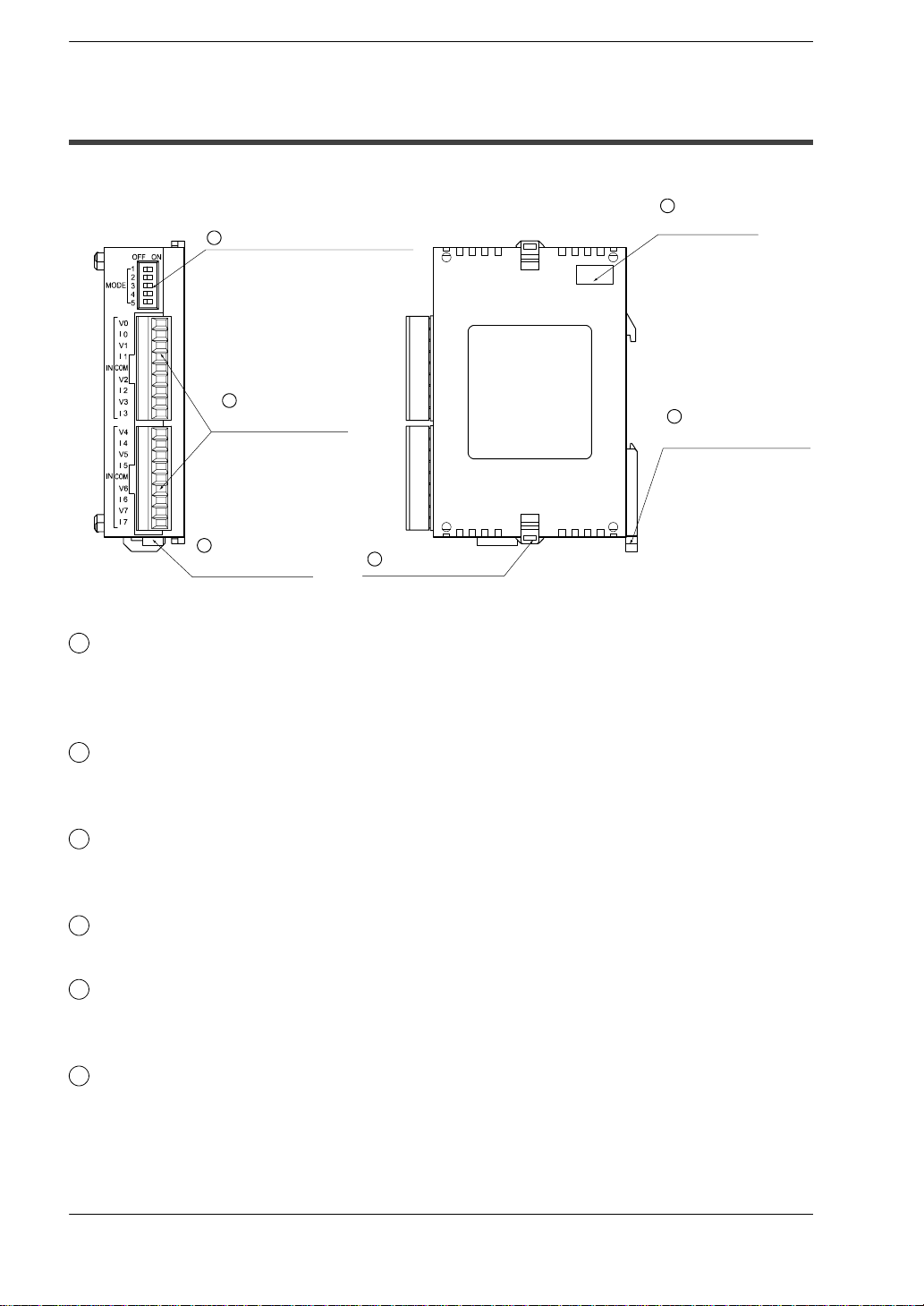
FP0−A80 A/D converter unit: AFP0401
1
Input range setting switch
2
Analog input
terminal block
FP0ーA80
3
Power supply
connector
6
Expansion hook
Parts and TerminologyFP0 A/D Converter Unit
1.1 Parts and Functions
4
Expansion
connector
5
DIN rail
attachment lever
1
Input range setting switch (voltage/current)
This switch is used to change the input mode (between voltage and current). All eight
input channels of the A/D converter unit operate at the same level. Refer to page 3−3
for details.
2
Analog input terminal block (9-pin)
Use a terminal block socket made by Phoenix Contact Co. (product number:
1840434).
3
Power supply connector
Supply 24V DC. It is connected using the power supply cable (AFP0581) that comes
with the unit.
4
Expansion connector
connects an expansion unit to the internal circuit of the this unit.
5
DIN rail attachment lever
allows simple attachment to a DIN rail. The lever is also used for installation on FP0
slim type mounting plate (AFP0803).
6
Expansion hook
is used to secure expansion units.
1 − 3
Parts and Terminology
1.2 Analog Input Terminal Block
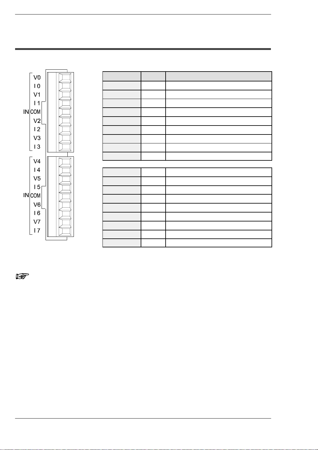
1.2 Analog Input Terminal Block
Pin number Name Description
1 V0 Analog input channel 0, voltage input
2 I0 Analog input channel 0, current input
3 V1 Analog input channel 1, voltage input
4 I1 Analog input channel 1, current input
5 COM Analog input, input common
6 V2 Analog input channel 2, voltage input
7 I2 Analog input channel 2, current input
8 V3 Analog input channel 3, voltage input
9 I3 Analog input channel 3, current input
1 V4 Analog input channel 4, voltage input
2 I4 Analog input channel 4, current input
3 V5 Analog input channel 5, voltage input
4 I5 Analog input channel 5, current input
5 COM Analog input, input common
6 V6 Analog input channel 6, voltage input
7 I6 Analog input channel 6, current input
8 V7 Analog input channel 7, voltage input
9 I7 Analog input channel 7, current input
FP0 A/D Converter Unit
1 − 4
Notes
• When the analog input is a current signal, short the V and I input pins
externally.
• The two COM terminals are connected internally.

Chapter 2
Connection to Input Devices
2.1 Wiring 2 − 3.........................................

FP0 A/D Converter UnitConnection to Input Devices
2 − 2
2.1 Wiring
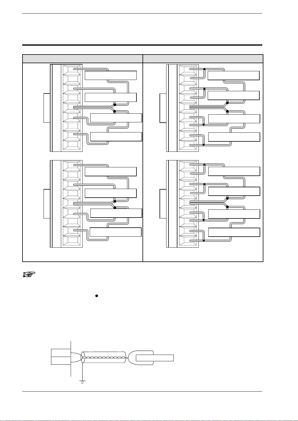
Voltage input Current input
Connection to Input DevicesFP0 A/D Converter Unit
2.1 Wiring
V0
I0
V1
I1
COM
V2
I2
V3
I3
V4
I4
V5
I5
COM
V6
I6
V7
I7
Input instrument (ch0)
Input instrument (ch1)
Input instrument (ch2)
Input instrument (ch3)
Input instrument (ch4)
Input instrument (ch5)
Input instrument (ch6)
Input instrument (ch7)
V0
I0
V1
I1
COM
V2
I2
V3
I3
V4
I4
V5
I5
COM
V6
I6
V7
I7
Input instrument (ch0)
Input instrument (ch1)
Input instrument (ch2)
Input instrument (ch3)
Input instrument (ch4)
Input instrument (ch5)
Input instrument (ch6)
Input instrument (ch7)
Connect input instrument between V terminal and COM
terminal.
Notes
• Tie the COM connectors for two channels together as indicated by the
black circles (“
wires go to each COM terminal.
”) in the diagram above so that no more than two
• The two COM terminals are connected internally.
• We recommend that you use dual−core twisted pair shielded wiring
for the analog input wiring, and that you connect the shield to earth.
V
COM
First, connect both V terminal and I terminal. And then
connect input instrument between it and COM terminal.
Input instrument
2 − 3

Connection to Input Devices
2.1 Wiring
FP0 A/D Converter Unit
2 − 4

Chapter 3
Input Range Setting
3.1 Input Range Setting Switch 3 − 3.......................
 Loading...