

Page 1
02/2006
FP
Σ
(Sigma)
Programmable Controller
Page 2

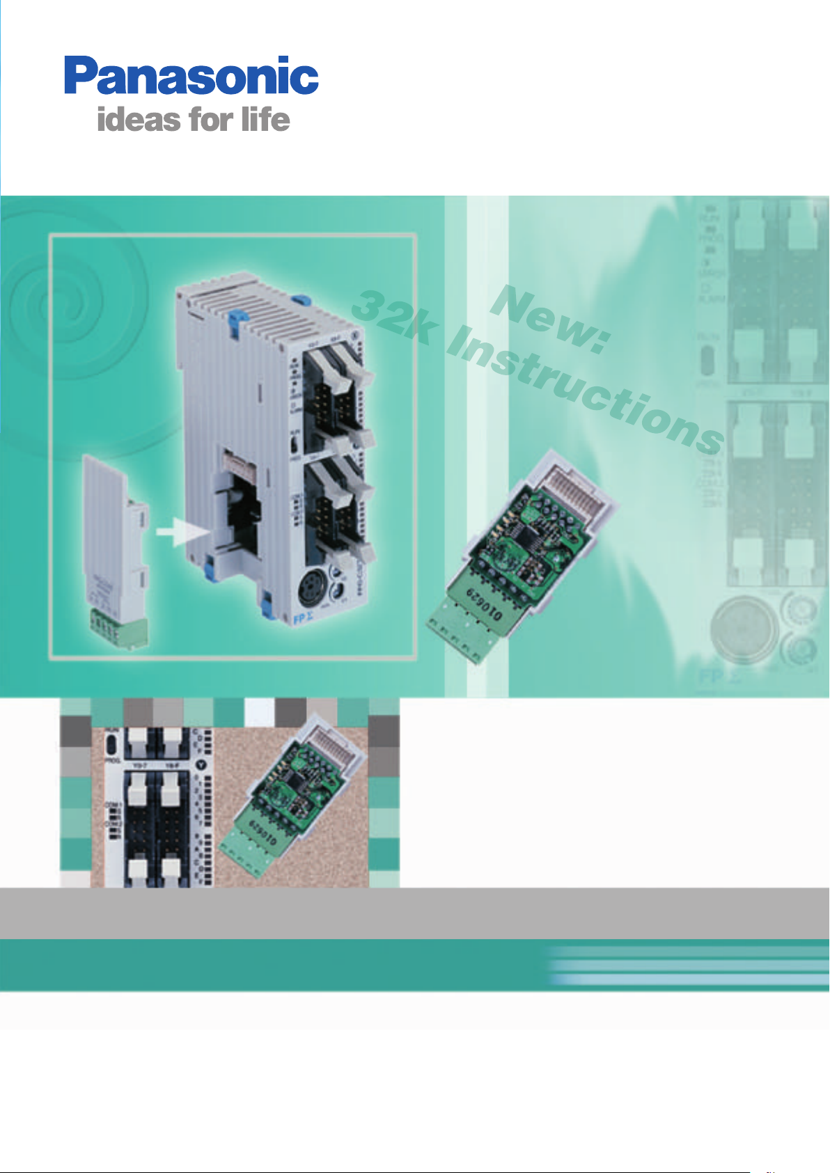
FPΣ (Sigma)
02/2006
The next generation compact PLC
Highlights
State-of-the-art PLC technology in the most compact size plus the ability to communicate via all important modern media
characterize the FP
positioning applications, a programming memory capable of storing 32,000 steps, a real-time clock, and communication interfaces
for RS232 and RS485, FP
Communication
Four quick and easy snap-on cassettes are available to add different
serial ports to the FP
at speeds of up to 115.2Kbps.
Σ (Sigma). With its two 100kHz pulse outputs, four hardware counters that function at up to 50kHz for
Σ (Sigma) is one of the most flexible PLCs on the market. Remarkably, it is also one of the smallest!
Σ (Sigma). All ports are capable of communicating
1-channel RS232C type.
2-channel RS232C type.
1-channel RS485 type.
1-channel RS232C + 1-channel RS485 type.
Positioning
In addition to a host of handy Panasonic functions,
the FP
Σ (Sigma) also offers circular and linear interpolation.
Circular interpolation can be used for applications that apply glue, linear
interpolation for pick & place applications, for example.
By combining the FP
2-axis motion control.
Σ (Sigma) with servo motors, you can perform real
Temperature Control
With the thermocouple input units and our accurate unique PID and
IPD algorithms, temperature can be controlled more easily and
accurately than ever.
FPΣ (Sigma)
Fast PID but
it overshoots
Driver Minas A series Motor Minas A series
No overshoots
but slow
FPΣ (Sigma) example
fast and no overshoot
Other Highlights
High expansion capability with up to 384 I/Os
Fastest processing time, 0.32µsec/basic command
Compact design (W 30 x H 90 x D 60mm)
2
Short circuit protected transistor outputs
Built-in analogue volume with two points
Backup battery
Page 3
FPΣ (Sigma)
0
10
30
40
50
60
70
80
02/2006
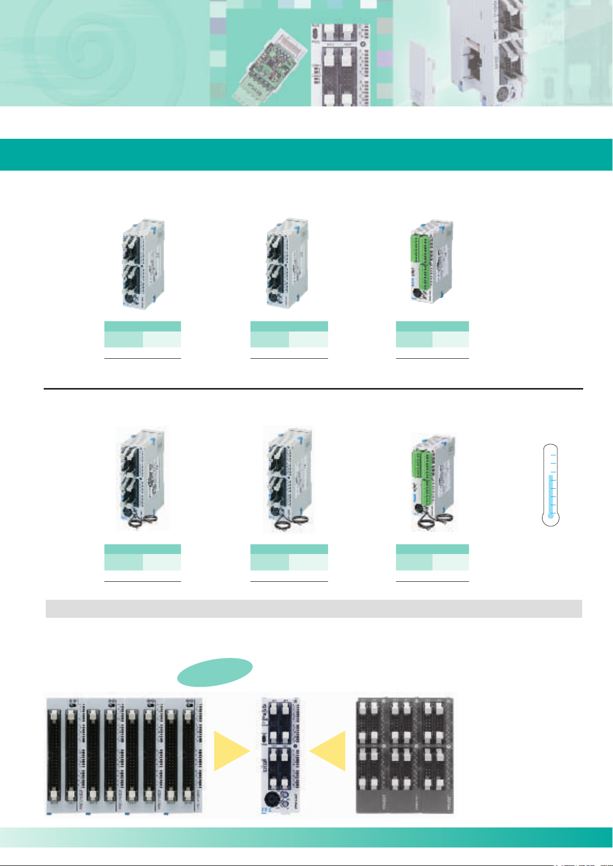
CPUs
Outstanding performance in a compact design
FPΣ(Sigma)– Transistor output type
28 points
Input
16 points
Σ(Sigma)– Transistor output type with thermistor input
FP
Output (PNP)
12 points
Connector type
FPG-C28P2H
32 points
Input
16 points
Connector type
FPG-C32T2H
Output (NPN)
16 points
FPΣ(Sigma
)
Relay output type
24 points
Input
16 points
Σ(Sigma)– Relay
FP
Output
8 points
Terminal type
FPG-C24R2H
output type with ther-
mistor input
Temperature
Control
28 points
Input
16 points
2 Thermistor inputs
FPG-C28P2HTM
Output
12 points
32 points
Input
16 points
2 Thermistor inputs
FPG-C32T2HTM
Output
16 points
24 points
Input
16 points
2 Thermistor inputs
FPG-C24R2HTM
Output
8 points
High Expansion Capability
FPΣ (Sigma) can use the expansion units of the FP0 on the right-hand side. New FPΣ (Sigma) units can be added to the left-hand
side.
Max. 4 Expansion Units
each 64 I/Os = 256 I/Os
…up to 384 I/O!
Parallel
Expansion
BUS
CPU
max. 32 I/Os
Max. 3 Expansion Units
each 32 I/Os = 96 I/Os
Serial
Expansion
BUS
3
Page 4

FPΣ (Sigma)
02/2006
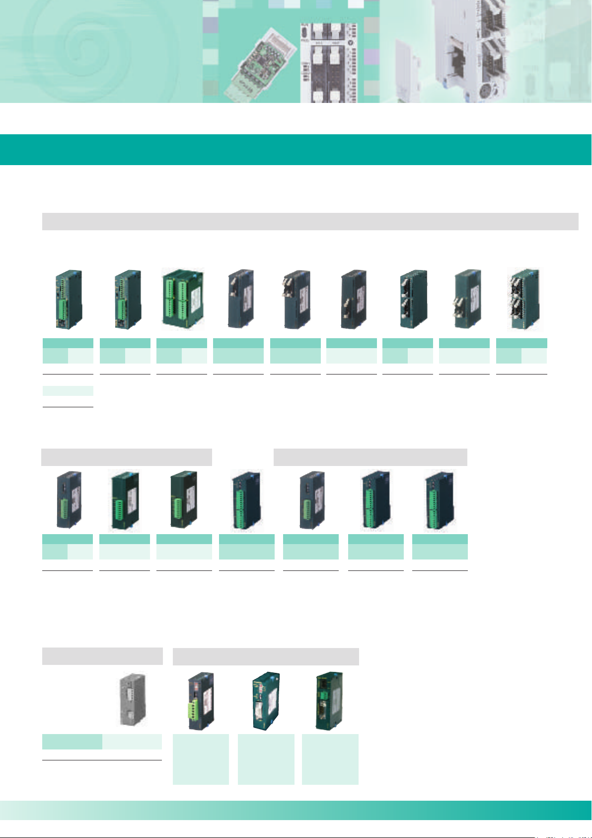
Expansion Units – Left Side Expansion
Wide variety of expansion units
FPΣ(Sigma
)
I/0 Expansion Unit
64 points
Input
32 points
Output (PNP)
32 points
MIL Connector type
FPG-XY64D2P
FPΣ(Sigma
I/0 Expansion Unit
64 points
Input
32 points
MIL Connector type
FPG-XY64D2T
)
Output (NPN)
32 points
FPΣ (Sigma)
Memory Expansion Unit
Memory: 256k words
FPΣ (Sigma) Positioning Expansion Units
FPG-EM1
FPG-EM1
FPΣ (Sigma)
S-Link Expansion Unit
S-Link Master
128 Inputs or outputs
FPG-SL
Transistor output
RS232C type
4
1-axis
FPG-PP11
1-channel
FPG-COM1
1-axis
Line driver output
FPG-PP12
2-axis
Transistor output
FPG-PP21
Line driver output
FPG-PP22
Communication Cassettes FP Memory Loader
• Read or write
programs from or
to a PLC
• Personal
computer is not
required
2-channel
RS232C type
FPG-COM2
1-channel
RS485 type
FPG-COM3
• Applicable with
2-channel
RS232C & RS485 type
FPG-COM4
Σ (Sigma),
FP0, FP
FP-M, FP2 and
FP2SH
AFP8670
2-axis
Page 5
FPΣ (Sigma) Expansion Units – Right Side Expansion
02/2006
Wide variety of expansion units
A maximum of 3 FP0 expansion units can be added to the CPU unit.
Digital I/O Units
Relay output type Input only type
8 points
Input
Output
4 points
4 points
Option:
Output 8 points
FP0-E8YRSA
16 points
Input
8 points
FP0-E16RSA FP0-E8XA FP0-E16XAFP0-E8RSA
Output
8 points
32 points
Input
16 points
FP0-E32RS
Output
16 points
8 points
Input
8 points
16 points
16 points
Input
Transistor output type
8 points
Output
8 points
FP0-E8YPA(PNP)
FP0-E8YTA(NPN)
16 points
Input
8 points
FP0-E16PA(PNP)
FP0-E16TA(NPN)
Output
8 points
Analogue I/O Units Temperature Control Units
16 points
Output
16 points
FP0-E16YPA(PNP)
FP0-E16YTA(NPN)
32 points
Input
Output
16 points
16 points
FP0-E32PA(PNP)
FP0-E32TA(NPN)
Input
Output
2 points
1 point
FP0-A21A
• Input (12 bit):
± 10V, 0 – 5V,
0 – 20mA
• Output (12 bit):
± 10V, 0 – 20mA
Output
4 points
FP0-A04I
–
–
4 – 20mA
AC Power Supply
FP0-PSA2
4 points3 points
Input
85 to 265VAC
Terminal type
Output
24VDC/0.7A
4 points
Output
4 points
FP0-A04V FP0-A80A
–
–
± 10V
8 points
Input
8 points
± 10V, ± 100mV
0 – 5V, 0 – 20mA
Networking Units
MEWNET-F
FP0-IOL
(MEWNET-F Slave)
PROFIBUS
FP0-DPS2
(DP Slave)
4 points
Input
4 points
FP0-TC4
• K, J, T, R type thermocouples
can be used
• Resolution: 0.1°C
• Accuracy: 0.8°C (R type: 3°C)
• Temperature range:
-100 to 1500°C
8 points
Input
8 points
FP0-TC8
Ethernet
FPWEB
(Web-Server Unit)
6 points
Input
6 points
FP0-RTD6
• Pt100, Pt1000,
Ni1000
• Temperature range:
-200 to 500°C
5
Page 6

FPΣ (Sigma)
02/2006
Optimised communication functions
1-channel RS232C type.
2-channel RS232C type.
1-channel RS485 type.
Four types of communication cassettes enable:
efficient connection to serial devices
transmission speeds of up to 115.2kbits/s
long transmission distance of up to 1200m
1-channel RS232C + 1-channel RS485 type.
In addition, the green screw terminal is removable
for easy wiring.
With the RS485 type communication cassette...
Despite being compact you can create powerful PLC links!
More links than you imagined a compact PLC could achieve
(2,048 link relays / 256-word link data registers)
Can be used to share product type between different machines.
Can be used for interlocking between different machines.
Easy wiring between PLCs with twin-core cabling.
Link data register
Product type data
Process
machine
Link data register
Product type data
Assembly
machine
RS485
Link data register
Product type data
Masterless communication method
(when PLC linkage is achieved with link relays and link data registers)
The masterless communication method means that even if a connected device (station) goes into power off, operations to
automatically switch the master station continue. Start up is smooth and the recovery from malfunctions is also potentially faster.
Previous models
Usual master-slave communication
If the master station is not on,
communication cannot take place.
Errors occur when devices are not
turned on in sequence.
With the
FPΣ (Sigma)
Masterless communication using the FPΣ (Sigma)
Even if a station goes into a power-
off state, communications between
the other stations continue.
Inspection
machine
Master
station
Slave
station
Slave
station
Slave
station
Slave
station
Link
station
Link
station
Use of insulated RS485
Uses the insulated RS485, which is highly reliable and largely impervious to noise.
High-speed communication over long distances are enabled.
Transmission speed: Max. 115.2kbits/s Transmission distance: Max. 1.200m
6
Link
station
Link
station
Page 7

FPΣ (Sigma)
02/2006
Optimised communication functions
Convenient station no. setting function enables flexible use, even when there are product type
changes.
Station no. switchability allows the use of unified programming and program switching.
Because even the communications parameters can be changed in the program, connection is enabled with
external devices that have different communication parameters.
FPΣ (Sigma) Station
No. setting switch
Great for these applications, too...
Computer linkage with up to 99 stations enabled (max. 32 stations when using C-NET adapter).
Ability to gather data from multiple stations means greater design freedom.
Previous models
Relay stations required for linking medium-scale PLCs
Computer
RS232C
RS232C
Commercial
adapter
Commercial
adapter
RS485
FP0
FP0
FP0
FP0
Communication parameters changed by instructions
With the
FPΣ (Sigma)
Computer linkage with up to 99 stations
Computer
RS232C
Commercial
adapter
FPΣFPΣ
RS485
FP
Σ
Can also be connected to external devices that are equipped with RS485 interface
Enables connection to external devices, such as temperature regulators,
that are equipped with RS485 interface.
Applicable with data gathering or setting adjustment.
Control is possible using
commercially available
RS485 devices.
GT11/GT30
RS232C
RS232C
FP
Σ
Example: Connection with
commercially available
temperature regulator
Temperature
regulator, etc.
RS485
With the RS232C type communications cassette
Efficient connection with other control devices helps to save space!
Enables connection to devices with RS232C interface, such as a
programmable display panel, image processing device and other devices.
When used as a tool port, up to 3 external devices can be connected.
A 2-channel type communication
cassette is used.
GT11/GT30
FP
RS232C RS232C
Σ
processing device
Temperature
regulator, etc.
Image
7
Page 8

FPΣ (Sigma)
Stepping motor
Servo motor
Motor
driver
1
Y0
Pulse output CW
Y1
Pulse output CCW
Y3
Pulse output CW
Y4
Pulse output CCW
Motor
driver
2
Adhesive
Motor
driver
Motor
driver
02/2006
Positioning
Specially designed for positioning applications
Max. 100kHz pulse output performance is now standard.
Powerful device capable of linear interpolation and circular interpolation.
Pulse output max. 100kHz
Because command processing at speeds up to 100kHz is available, highspeed, high-precision positioning is enabled. Along with stepping motor
control, the specs also ensure plenty of scope for controlling servomotors.
Possible to combine with pulse-train input drivers
Single unit enables two-axis control
Rapid 0.02ms start (when JOG operation controls are executed)
The time taken to execute the JOG operation, from the instant the trigger (execution condition) goes on to the time of pulse output,
is 0.02ms and 0.2ms even with trapezoidal control. Control time is reduced even for machines that quickly and repeatedly restart.
Linear interpolation and circular interpolation are built in (FPG-C32T2H and FPG-C28P2H)
Interpolation functions enable simultaneous control of two axes.
Applications that a compact PLC couldn't previously cope with are no
longer a challenge.
Linear Interpolation Circular Interpolation
And there’s more...
Smooth acceleration/deceleration
You can choose to set either 30 or 60 steps of acceleration/
deceleration. This feature means you can achieve smoother
movement during long acceleration/ deceleration periods of
stepping motors.
The settings are there for a maximum 60
accelaration/deceleration steps.
8
Support for CW/CCW method
Reduce overall costs by designing systems that combine with
servomotors and small stepping motors without support for
Pulse and Sign method.
CW / CCW
method
Pulse / Sign
method
Page 9

FPΣ (Sigma)
Home sensor
ON
XA ON
2000Hz
100Hz
0Hz
150ms
ON
OFF
300Hz
0Hz
XB (JOG command)
Y0 (Pulse)
X-axis
(CH0)
Y-axis
(CH2)
5000
2000
Pass position P
(X 9396, Y -3420)
Target position E
(X 8660, Y -5000)
Current position S
(X 5000, Y 8660)
Center position O
(Xo,Yo)
02/2006
Positioning
High-speed, high precision positioning
Programming with convenient and
easy-to-understand instructions
Uses a preset value table for starting speed, target speed,
acceleration/ deceleration time, and other factors. Easy-tounderstand programming is possible since numbers can be
specified intuitively.
Comes with dedicated instructions for each mode: trapezoidal
control, home return, JOG operation, free table operation,
linear interpolation, and circular interpolation.
Home position return
Pulse output diagram
(when the home position proximity input is not used).
Selectable home return mode
The home return method may be specified even in situations
such as when only a single sensor is being used, depending
on the design.
When the home position return is completed, a deviation
counter clear signal can also be output.
JOG operation
Pulse output diagram
Home search automatically reverses the motor rotation when
Over limit input(+) or Over limit input (-) is input and their
searches for the home position or near home position in order
to return to it automatically.
Linear interpolation
Positioning Iocus.
A control function that automatically defines the continuum of
points in a straight line based on only two co-ordinate positions.
This refers to an operation in which the motor is rotated only
while operation commands are being input. This is used to
forcibly rotate the motor using input from an external switch, for
instance when making adjustments. Depending on the
circumstances, unlimited feeding can be accomplished with the
JOG operation in some cases.
Circular interpolation
Positioning Iocus.
Center-radial
setting methods are
also available.
Allows points to be smoothly traversed by arced paths for which
the user specifies the orientation plane, the radius of curvature,
motion path profile, and direction of motion.
9
Page 10

FPΣ (Sigma)
02/2006
Positioning Expansion Units
Precise positioning
Features
Fast startup of 0.02 or 0.005ms makes cycle time reduction possible.
Feedback pulse count function makes output pulse counting from external encoders possible.
JOG positioning control supports a wide range of applications.
4 types of S-curve acceleration/ deceleration control makes smooth startup and stopping possible:
Sine curve, quadratic curve, cycloid curve and cubic curve.
FPG-PP11 FPG-PP12 FPG-PP21 FPG-PP22
The FPΣ (Sigma) positioning unit can handle simultaneous startup of multiple axes, enabling
simultaneous control of linear interpolation and other elements through user programs.
Transistor output type (open collector) and line driver output type are available.
Unit type and product number
Type Output type Part number
1 - axis type Transistor output type FPG-PP11
2 - axis type Transistor output type FPG-PP21
1 - axis type Line driver output type FPG-PP12
2 - axis type Line driver output type FPG-PP22
10
Page 11

Optimised Temperature Control
Thermistor
FP• control unit that
accepts thermistors
02/2006
Functions convenient for temperature control are built in
The control unit with thermistor inputs enables temperature control at low cost
Two thermistor inputs, which cost less than thermocouples,
can be connected to the FP
(FPG-C28P2HTM, FPG-C32T2HTM and FPG-C24R2HTM).
Using a simple linearization command, measuring
the temperature by the thermistor can be programmed easily.
Σ (Sigma) unit via thermistor inputs
FPΣ (Sigma) control unit
that accepts thermistors
Four- and eight-channel type thermocouple input expansion unit
Up to three units can be added to each control unit, enabling temperature
control of up to 24 channels.
Advantages over multiple temperature controllers:
Information collection and computer-based storage.
On-site error monitoring using programmable display.
Significant reduction in total costs.
Power supply stabilisation by protecting synchronisation
between heater ON and OFF states.
Temperature settings can be easily changed using batch function.
Optimised temperature control with PID and PWM instruction
You can easily set multi-stage temperature control and time
control usually available only in high performance type
temperature controllers.
With the built-in PID and IPD algorithms,
temperature can be controlled more accurate
than ever.
Example of temperature control
with the auto-tuning function only
11
Page 12

FPΣ (Sigma)
FP-e FP-XFP2/FP2SH
Can be used as a master station [F145 (Write) and F146 (Read) instructions]
Can easily communicate with temperature controllers, inverters, FP-e, and overseas
PLCs.
Also serves as
a slave station.
Temperature
controller
Power meter Inverter
Token passing
Master/
Slave
Master/
Slave
Master/
Slave
Master/
Slave
A multi-master link
of up to 99 units
can be created.
02/2006
Supports the enhancement of your equipment’s performance
Network enhancement
Modbus-compatible
FP
Σ (Sigma) is compatible with the world's
FPΣ(Sigma) can serve as Modbus Master or Slave
de facto standard Modbus* and can serve
as both Modbus RTU master and slave,
making it ideal for air conditioning or
temperature control etc.
* Protocol developed by Modicon Inc., an American company
These applications are also available.
When 17 or more FP
Σ (Sigma) units need to be
linked, you can use the Modbus function instead
of MEWNET-W0 to link up to 99 units. Since each
FP
Σ (Sigma) unit can be either a master or a slave,
a multi-master link can be created by passing a
token from a user program.
New “MEWTOCOL Master” function is available.
The MEWTOCOL master function automatically creates and transmits commands using the Panasonic open
protocol MEWTOCOL. This function significantly facilitates serial communications with MEWTOCOLcompatible equipment, such as PD50, KT4H and KW4M.
RS232C
Temperature
Controller
KT4H
RS485
2D Code Reader
PD50
Eco Power Meter
KW4M
Security enhancement
Programs are copy-protected by the upload restriction setting and an eight-character password.
The setting to inhibit the uploading of PLC programs to PCs protects your programs from unauthorized
copying. (If this setting is released, programs in the PLC are forcibly cleared.)
An eight-character password has been adopted. (The conventional four-character password is also available.)
Approx. 218 trillion passwords can be set by combining eight alphanumeric characters, making it nearly
impossible to crack the password set.
Debugging performance enhancement
Up to 512 steps can be rewritten simultaneously in RUN mode.
This improvement allows efficient program debugging without stopping the operation.
12
Page 13

FPΣ (Sigma) Data Memory Expansion Unit
PROG.
RUN
COM.1
S
R
COM.2
S
R
X0-7
Y0-7
X8-F
Y8-F
RUN
PROG.
ALARM
ERROR
0
2
4
6
1
3
5
7
8
A
C
E
9
B
D
F
0
2
4
6
1
3
5
7
8
A
C
E
9
B
D
F
V1
V0
min.
max.
02/2006
Data capacity expandable up to 256k words
Features
Able to store 256k words, this memory unit is well-suited for storing remote monitoring logs.
Take advantage of FPΣ‘s (Sigma) memory for manufacturing systems that produce more than one model.
With FP
manufactury process.
Up to 4 units can be connected to the FPΣ (Sigma), allowing up to 1024k words to be stored.
Σ‘s (Sigma) memory, you no longer need to download new production data every time you switch
FPG-EM1
General Specifications
Item Description
Ambient temperature/
0 to 55°C, 30 to 85% RH (No condensation)
humidity
Storage temperature/
–20 to +70°C, 30 to 85% RH (No condensation)
humidity
Vibration resistance
10 to 55Hz, 1 sweep/min., double amplitude of 0.75mm,
10min. on 3 axes
Shock resistance 98m/s2 or more, 4 times on 3 axes
Noise immunity
1,000V (P-P) with pulse width 50ns, 1µs
(using a noise simulator)
Basic unit mass Approx. 80g
The amount of increase
in control unit
35mA or less (24VDC)
(100mA or less (internal 5VDC)
consumption current
Performance Specifications
Item Description
Memory capacity
Battery life 5 years or more
5V Power consumption 100mA or less
Number of I/O points Input 16 points
256 kilowords (1k words x 256 banks)
Programming tool FPWINGR/FPWIN Pro
Instructions F150 and F151 are necessary for reading
from and writing to memory expansion units.
You can use these instructions with FPWINGR Vers.
2.13 or later or FPWIN Pro Vers. 4.02 or later.
Data is read with the
F150 instruction.
Data is written with
the F151 instruction.
13
Page 14

FPΣ (Sigma) S-Link Expansion Unit
S-LINK unit
35 μs
DC
24 V
02/2006
Flexible wire-saving link system S-Link
Features
Up to four S-Link units can be attached to one FPΣ (Sigma) CPU.
Each unit supports up to 128 I/O signals over a pair of wires up to a distance of 200m
(400m when a booster is used).
The combination of input and output point quantities (a total of 128 points max.) can be set by
the rotary switch in increments of 32 points.
The transmission line connection is realized via a T-branch multi-drop wiring with hook-up
connectors. Adding devices is rendered easy and maintenance is easy.
FPΣ (Sigma) + S-Link unit
Features
The four-wire cable (two signal wires and two power
wires) enables efficient wiring, and the T-branch wirinig
enables a flexible connection layout.
About 60 types of S-Link input/output devices can be
connected to this unit, enabling it to meet diverse I/O
needs. In addition, the high transmission voltage
(24VDC) and the wide clock width (35µs) provide high
noise immunity. Flexible and reliable wiring is available,
reducing the wiring work.
Features
The control unit automatically recognizes I/O allocation in accordance with the attached S-Link unit
position, making the S-Link unit as easy to use as a common expansion I/O device.
If the main wire is broken and an input/output device cannot be recognized, then the S-Link unit displays
the device number. This function significantly reduces the time required for troubleshooting during an
equipment startup check or recovering from on-site problems.
FPG-SL
Specifications
Transmission method Bi-directional time-divided multiple signal transmission
Synchronization Bit synchronization, frame synchronization
Transmission protocol S-Link protocol
Transmission line Exclusive flat cable or cabtyre cable
Transmission speed 28.5 kbps
Transmission distance *
Connection method T-branch multi-drop wiring or multi-drop wiring
Number of I/O points 128 points max. (adjustable in encrements of 32 I/O points)
1 For broosters, see the S-Link catalog and manual issued by SUNX Limited.
*
1
Main signal wires: Extensible up to 200m (400m when a booster is used)
14
Page 15

FP Web-Server
02/2006
Program/Operate the FP
The multifunctional FP Web-Server provides users with the option of connecting the FPΣ (Sigma) or any other
FP Series PLC to the Internet/Intranet thus enabling bi-directional communication. No changes to the PLC
programs are necessary. Simply assign an IP address to the FP Web-Server and connect the PLC to the
FP Web-Server via the serial RS232C interface. A standard browser e.g. MS Internet Explorer or Netscape
Navigator can be used for access at the PC.
The FP Web-Server´s 3 interfaces
10BaseT (RJ45, twisted pair)
– connects to the Ethernet at 10 Mbit/s
RS232C (screw terminal)
– connects to the FP
RS232C (SUB-D 9 male)
– connects to a modem (PPP)
Σ (Sigma) using a LAN or WAN network
Σ (Sigma) at 1200 to 115.2 kbit/s
Highlights
Web-Server:
-PLC data represented as HTML (or XML) pages
-Access via standard Internet browser
-PLC data handling via HTML and Java Applet
-Optional: Password protection, IP-Lok security
Email:
-PLC can send emails
-Email via LAN email server or Internet dial-up
-PLC-defined or pre-stored mail text
-PLC data array as attachment to an email
RS232C device server:
-Ethernet <–> RS232C conversion (MEWTOCOL)
-Transparent RS232C data tunneling via Ethernet
-Programming and visualisation via TCP or UDP
Modbus- TCP protocol:
-Communication via standard industrial Ethernet
protocol (server and client)
Protocols TCP/IP, UDP/IP, SMTP, PPP, NTP, FTP, TELNET, HTTP, MEWTOCOL-COM
Number of browsers Up to 64 browsers can be connected to one FP Web-Server
Number of emails
Number of email addresses
Number of PLC per unit
IP address DHCP or manually set by software
Security Password and DIP switch
Operating power 24VDC, 75mA (max.)
Dimensions 25 x 90 x 60mm (W x H x D)
LEDs Power, COM Ethernet connection, COM data exchange
Flash memory 512KBytes
Standards fulfilled CE, UL, cUL
4 predefined in FP Web Flash memory
1 programmable in PLC DT memory as ASCII
4 predefined in FP Web flash memory, 1000 addresses in PLC DT memory,
assuming an average of 32 characters are used per email address and that an
FP0-T32CP is used, which has 16k word memory
Two PLCs can be connected
3-pin port (port number: 9094)
DB8 port (port number: 9095)
Modem/Ethernet gateway:
-FP Web-Server can be dialed up via modem
-One remote gateway for multiple FP Web-Servers in
a local Ethernet network
Network time server synchronisation:
-PLC real-time clock update via NTP server
15
Page 16

Control FPWIN Pro
02/2006
Programming according to the international standard IEC 61131-3
FPWIN Pro is the Panasonic programming software developed according to the international standard
IEC 61131-3 (for Windows 98, NT V4.0, 2000, ME or XP). This new version is a result of experience gained
over many years. We were one of the first PLC manufacturers to offer an IEC 61131-3 programming software,
and we are a leading member of the international organisation PLCopen.
Input and output variables
are defined once in the
global variable list
Multiple address assigment
is caught automatically
by the compiler
Local variables are allocated
automatically by the compiler
Type safe programming using
simple or complex data types
Comfortable programming in the
graphical LD editor (ladder diagram)
Functions can be saved in
libraries for future reuse
Navigator with tree
representation of called
functions provides an
overview even for very
complex projects
The SFC editor (Sequential
Function Chart) allows you to
easily visualize processes
Structuring with
selection statements
Using loops for running
through incoming data
...or arrays
Additional window for monitoring
and forcing variables
Using alliases names for PLC-independent
access on the special data registers, e.g. RTC
Easy handling of
formulas and
arithmetic
expressions
Special functions for controlling the
SFC program from another program
The ST editor
(Structured Text)
solves complex
programming tasks
Using STRING
functions for analyzing
incoming data...
...or for generating
formatted output
strings
One instruction for different
data types (overloaded instructions)
Temporary variables are allocated
and released automatically by the
compiler
Long variable names make the
program self-explanatory
Free demonstration disc
The most important highlights at a glance:
One software for all FP Series PLCs.
5 programming languages (instruction list, ladder diagram, function block diagram,
sequential function chart, structured text) available for all PLCs.
Programme organisation units, task and project management provide clear structure.
Reuse of ready-made functions and function blocks saves time for programming and debugging.
Online monitoring and diagnostics.
Forcing – Turning off input and output contacts via the PC.
Modem communication for remote programming, service and diagnostics.
Extensive comments – online documentation created hand in hand with the program.
Part numbers:
FPWINPROF: Full version
FPWINPROS: Small version,
6 languages are supported: English, German, French, Italian, Spanish and Japanese.
16
supports all FP Series PLCs
supports FP-e, FP0, FP-M,
FP1, FP-X and FPΣ (Sigma)
Page 17

FPΣ (Sigma)
02/2006
Specification tables
PP EE RR FF OO RR MM AA NN CC EE SS PP EE CC II FF II CC AATT II OO NN SS
Item Description
Type of control unit NPN transistor output type PNP transistor output type Relay output type
Part number FPG-C32T2H/FPG-C32T2HTM FPG-C28P2H/FPG-C28P2HTM FPG-C24R2H/FPG-C24R2HTM
Number of I/O points
No expansion
with expansion Max. 384 Max. 380 Max. 376
Program memory Built-in Flash ROM
Program capacity 32.000 steps
Operation speed 0.32 µs- /step, Basic instructions
Memory for execution
External input (X) 1184 points
External output (Y) 1184 points
Internal relay (R) 4096 points (R0 to R255F)
Timer/Counter (T/C)
Link relay (L) 2048 points
Data register (DT) 32765 words (DT0-DT32764)
Link data register (LD) 256 words
Index register (I) 14 words (I0-ID)
Differential points Unlimited number of points
Master control relay points 256 points
Labels (JP+LOOP) 256 labels
Number of step ladder 1000 stages
Number of subroutine 100 subroutines
High-speed counter Single-phase: 1ch: 50kHz/2ch: 30kHz/3 or 4ch: 20 kHz / Two-phase: 1ch: 20kHz/2ch: 15kHz
Pulse output 1 channel: 100kHz / 2 channel: 60kHz
PWM output 2 channels, 1.5 to 12.5 kHz (at resolution of 1000) / 15.6 to 41.7 kHz (at resolution of 100)
Pulse catch input 8 points (X0-X7)
Interrupt program 9 programs (external 8 points, 1 periodical interrupt point 0.5ms - 30s)
Self-diagnosis functions Watchdog timer, program syntax checking, etc.
Clock/Calendar function Year, month, day, hour, minute, second, and day of week
Volume input 2 points resolving power 10bits (K0-K1000)
Thermistor input 2 points, resolution: 10 bits (0 to 1000) (for C32T2HTM, C24R2HTM, and C28P2HTM only)
Link functions Computer link (1:1, 1:N)
Battery life (Battery is optional) 220 days or more* (actual usage value: approx. 840 days (25°C). Suggested replacement interval: 1 year
Comment storage
Linear/circular interpolution for positioning Available Available Not available
Other functions
32 (Input: 16 / Output: 16) 28 (Input: 16 / Output:12) 24 (Input: 16 / Output: 8)
1024 points
1, 2
/ At reset: timer 1008 points (T0-T1007), counter 16 points
( C1008-C1023), Timer range is selected by instructions from 1ms, 10ms, 100ms,
1s / Counter: 1 to 32767 counts
3, 4
General communication (1:1, 1:N)
1
1
1
6
3, 4
PLC link
5
All kinds of comments, including I/O comments, remarks and block comments, can be stored (without backup battery)
Program edition during run, constant scan, forced I/O, password,
floating point real number operation, PID processing instruction
Comment memory 128Kbyte
Notes: 1) If a battery is not used, only fixed area is backed up (Counter: C1008-C1023, internal relay: R900-R97F, Data register: DT32710-
DT32764). If a battery is used, backup is possible: Area-setting of hold or no-hold is possible by system register.
2) Points can be increased using auxiliary timer.
3) Optional communication cassette (RS232C type) is necessary for 1:1 communication.
4) Optional communication cassette (RS485 type) is necessary for 1:N communication.
5) Optional communication cassette (RS485 type) is necessary.
6) Optional battery is necessary in order to use Clock/Calendar function. Precision calendar timer: at 25°C = 77°F less than 51-second
error per month / at 0°C = 32°F less than 119-second error per month / at 55°C = 131°F less than 148-second error per month.
*Value applies when no power is supplied at all.
17
Page 18

FPΣ (Sigma)
02/2006
Specification tables
II NN PP UU TT SS PP EE CC II FF II CC AATT II OO NN SS
Insulation method Optical coupler
Rated input voltage 24VDC
Input voltage range 21.6 to 26.4VDC
Rated input current 3.5mA - 8mA depends on input no.
Input points per common
Min. ON voltage / Max. OFF current 19.2V / 3mA - 6mA depends on input no.
Max. ON voltage / Min. OFF current 2.4V / 1.3mA
Input impedance 3k - 6.8k depends on input no.
Response time CPU: 1ms or less, 5µs (HSC, pulse catch, interrupt input)
Expansion: 0.2ms (OFF -> ON)
Operating indicator LED
OO UU TT PP UU TT SS PP EE CC II FF II CC AATT II OO NN SS -- TT RR AA NN SS II SS TT OO RR OO UU TT PP UU TT TT YY PP EE
Item FPG-C32 (NPN) FPG-C28 (PNP)
Insulation method Optical coupler
Output method Open collector
Rated voltage range 5 to 24VDC 24VDC
Operating load voltage range 4.75 to 26.4VDC 21.6 to 26.4VDC
Max. load current
Max. surge current
Output points per common 16 points/common 12 points/common
OFF -> ON
Response time
Power supply for driving internal circuit none
Operating indicator LED
Phase fault protection Thermal protection for Y2, Y5 and higher
ON -> OFF
8 points/common (FPG-C24), 16 points/common (FPG-C32/C28),
32 points/common (FPG-XY64). Either the positive or
negative of input power supply can be connected to terminal
0.3ms (ON -> OFF)
For Y0, Y1, Y3, Y4: 0.3A For Y0, Y1, Y3, Y4: 0.5A
For Y2, Y5 to YF: 0.1A For Y2, Y5 to YB: 0.3A
For Y0, Y1, Y3, Y4: 0.9A For Y0, Y1, Y3, Y4: 1.5A
For Y2, Y5 to YF: 0.5A For Y2, Y5 to YB: 0.7A
For Y0, Y1, Y3, Y4 at 15mA or lesss: <2µs
For Y2, Y5 and higher: < 0.2ms
For Y0, Y1, Y3, Y4 at 15mA or lesss: <8µs
For Y2, Y5 and higher: < 0.5ms
OO UU TT PP UU TT SS PP EE CC II FF II CC AA TT II OO NN SS -- RR EE LL AA YY OO UU TT PP UU TT TT YY PP EE
Output type Normally open (1 Form A)
Rated control capacity 2A 250VAC, 2A 30VDC (max. 4.5A/common)(resistive load)
Output points per common 8 points/ common
Response time
Mechanical life time 20 million operations or more
Electrical life time 100.000 operations or more
Surge absorber 21.6 to 26.4VDC (70mA)
Operating indicator LED
GG EE NN EE RR AA LL SS PP EE CC II FF II CC AATT II OO NN SS
Rated operating voltage 24VDC
Operating voltage range 21.6 to 26.4VDC
Allowable no voltage time 4ms (at 21.6V), 10ms (at 26.4V)
Ambient temperature 0°C to +55°C
Storage temperature -20°C to +70°C
Ambient humidity 30 to 85% RH (Non-condensing)
Storage humidity 30 to 85% RH (Non-condensing)
Vibration resistance 10 to 55Hz, 1 cycle/min.,
OFF -> ON
ON -> OFF
double amplitude of 0.75mm,
10min. on 3 axes
10ms or less
8ms or less
Shock resistance 98m/s2or more,
Noise humidity 1,000V (p-p)
Operating condition free from corrosive gasses
4 times on 3 axes
widths 50ns and 1µs
and excessive dust
18
with pulse
Page 19

FPΣ (Sigma)
02/2006
Product Overview
Part numbers
FF PP ΣΣ (( SS II GG MM AA )) CC OO NN TT RR OO LL UU NN II TT SS
Product Name Part Number
FPΣ C28 CPU, 16 inputs, 12 outputs (transistor PNP) FPG-C28P2H
FPΣ C32 CPU, 16 inputs, 16 outputs (transistor NPN) FPG-C32T2H
FPΣ C24 CPU, 16 inputs, 8 outputs (relay) FPG-C24R2H
FPΣ C28 CPU, 16 inputs (+ 2 thermistor inputs) , 12 outputs (transistor PNP) FPG-C28P2HTM
FPΣ C32 CPU, 16 inputs (+ 2 thermistor inputs) , 16 outputs (transistor NPN) FPG-C32T2HTM
FPΣ C24 CPU, 16 inputs (+ 2 thermistor inputs), 8 outputs (relay) FPG-C24R2HTM
FF PP ΣΣ (( SS II GG MM AA )) EE XX PPAA NN SS II OO NN UU NN II TT SS (( LL EE FF TT SS II DD EE EE XX PP AA NN SS II OO NN ))
Product Name Part Number
FPΣ 64-points I/O Expansion Unit, 32 inputs, 32 outputs (transistor PNP) FPG-XY64D2P
FPΣ 64-points I/O Expansion Unit, 32 inputs, 32 outputs (transistor NPN) FPG-XY64D2T
FPΣ Memory Expansion Unit, 256k words FPG-EM1
FPΣ Positioning Expansion Unit, 1 axis type, transistor output FPG-PP11
FPΣ Positioning Expansion Unit, 1 axis type, line driver output FPG-PP12
FPΣ Positioning Expansion Unit, 2 axes type, transistor output FPG-PP21
FPΣ Positioning Expansion Unit, 2 axes type, line driver output FPG-PP22
FPΣ S-Link Master Expansion Unit FPG-SL
FPΣ CC-Link Slave Expansion Unit FPG-CCLS
FF PP ΣΣ (( SS II GG MM AA )) AA CC CC EE SS SS OO RR II EE SS
Product Name Part Number
FPΣ 1 channel, RS232C type communication cassette FPG-COM1
FPΣ 2 channels, RS232C type communication cassette FPG-COM2
FPΣ 1 channel, RS485 type communication cassette FPG-COM3
FPΣ 2 channels, RS232C & RS485 type communication cassette FPG-COM4
FPΣ power supply cable, 1m AFPG805
FPΣ battery, for memory backup & clock functions AFPG804
FP Memory Loader, for transfer of programs without a PC or memory unit AFP8670
FF PP 00 EE XX PP AA NN SS II OO NN UU NN II TT SS (( RR II GG HH TT SS II DD EE EE XX PP AA NN SS II OO NN ))
Product Name Part Number
FP0-E8RS, 4 inputs, 4 outputs (relay) FP0-E8RSA
FP0-E8X, 8 inputs FP0-E8XA
FP0-E8YP, 8 outputs (transistor PNP) FP0-E8YPA
FP0-E8YT, 8 outputs (transistor NPN) FP0-E8YTA
FP0-E16RS, 8 inputs, 8 outputs (relay) FP0-E16RSA
FP0-E16P, 8 inputs, 8 outputs (transistor, PNP) FP0-E16PA
FP0-E16T, 8 inputs, 8 outputs (transistor, NPN) FP0-E16TA
FP0-E16X, 16 inputs FP0-E16XA
FP0-E16YP, 16 outputs (transistor PNP) FP0-E16YPA
FP0-E16YT, 16 outputs (transistor NPN) FP0-E16YTA
FP0-E32P, 16 inputs, 16 outputs (transistor, PNP) FP0-E32PA
FP0-E32T, 16 inputs, 16 outputs (transistor, NPN) FP0-E32TA
FP0-E32RS, 16 inputs, 16 outputs (relay) FP0-E32RS
FP0-A21A, 2 analogue inputs, 1 analogue output FP0-A21A
FP0A04V, 4 analogue outputs, -10 to 10V FP0-A04V
FP0-A04I, 4 analogue outputs, 4 to 20mA FP0-A04I
FP0-A80A, 8 analogue inputs FP0-A80A
FP0 thermocouple unit, 4 inputs FP0-TC4
FP0 thermocouple unit, 8 inputs FP0-TC8
FP0 RTD input unit, 6 inputs FP0-RTD6
FP0 PROFIBUS DP slave or remote I/O unit FP0-DPS2
FP0 I/O link unit (MEWNET-F slave) FP0-IOL
AA CC PP OO WW EE RR SS UU PP PP LL YY
Product Name Part Number
FP0 AC power supply, 24VDC, 0.7A FP0-PSA2
19
Page 20

Global Network
02/2006
Global Network Services
Asia Pacific China JapanNorth America Europe
Panasonic Electric Works
Please contact our Global Sales Companies in:
Europe
Headquarters Panasonic Electric Works Europe AG Rudolf-Diesel-Ring 2, 83607 Holzkirchen, Tel. (08024) 648-0, Fax (08024) 648-111, www.panasonic-electric-works.com
Austria Panasonic Electric Works Austria GmbH Josef Madersperger Str. 2, 2362 Biedermannsdorf, Tel. (022 36) 268 46, Fax (022 36) 461 33, www.panasonic-electric-works.at
Benelux Panasonic Electric Works
Czech Republic Panasonic Electric Works Czech s.r.o. Prumyslová 1, 34815 Planá, Tel. 374 799 990, Fax 374 799 999, www.panasonic-electric-works.cz
France Panasonic Electric Works
Germany Panasonic Electric Works Deutschland GmbH Rudolf-Diesel-Ring 2, 83607 Holzkirchen, Tel. (08024) 648-0, Fax (08024) 648-555, www.panasonic-electric-works.de
Ireland Panasonic Electric Works UK Ltd. Dublin, Tel. (01) 4600969, Fax (01) 4601131, www.panasonic-electric-works.co.uk
Italy Panasonic Electric Works Italia s.r.l. Via del Commercio 3-5 (Z.I. Ferlina), 37012 Bussolengo (VR), Tel. (045) 6752711, Fax (045) 6700444, www.panasonic-electric-works.it
Nordic Countries Panasonic Electric Works Nordic AB Sjöängsvägen 10, 19272 Sollentuna, Sweden, Tel. (08) 59476680, Fax (08) 59476690, www.panasonic-electric-works.se
Portugal Panasonic Electric Works España S.A. Portuguese Branch Office, Avda Adelino Amaro da Costa 728 R/C J, 2750-277 Cascais, Tel. (21) 4812520, Fax (21) 4812529
Spain Panasonic Electric Works España S.A. Barajas Park, San Severo 20, 28042 Madrid, Tel. (91) 3293875, Fax (91) 3292976, www.panasonic-electric-works.es
Switzerland Panasonic Electric Works Schweiz AG Grundstrasse 8, 6343 Rotkreuz, Tel. (041) 7997050, Fax (041) 7997055, www.panasonic-electric-works.ch
United Kingdom Panasonic Electric Works UK Ltd. Sunrise Parkway, Linford Wood, Milton Keynes, MK14 6LF, Tel. (01908) 231555, Fax (01908) 231599, www.panasonic-electric-works.co.uk
PEW Electronic Materials Europe GmbH Ennshafenstraße 30, 4470 Enns, Tel. (0 72 23) 8 83, Fax (0 72 23) 8 83 33, www.panasonic-electronic-materials.com
Sales Western Europe B.V.
Sales Western Europe B.V.
PEW Electronic Materials France S.A.R.L. 26 Allée du Clos des Charmes, 77090 Collegien, Tél. 01 64622919, Fax 01 64622809, www.panasonic-electronic-materials.com
PEW Building Materials Europe s.r.l. Viale Elvezia 18, 20154 Milano (MI), Tel. (02) 33604525, Fax (02) 33605053, www.panasonic-building-materials.com
PEW Fire & Security Technology Europe AB Citadellsvägen 23, 21118 Malmö, Tel. (040) 6977000, Fax (040) 6977099, www.panasonic-fire-security.com
De Rijn 4, (Postbus 211), 5684 PJ Best, (5680 AE Best), Netherlands, Tel. (0499) 372727, Fax (0499) 372185, www.
French Branch Office, B.P. 44, 91371 Verrières le Buisson CEDEX, Tél. 01 60135757, Fax 01 60135758, www.panasonic-electric-works.fr
panasonic-electric-works
.nl
North & South America
USA PEW Corporation of America 629 Central Avenue, New Providence, N.J. 07974, Tel. 1-908-464-3550, Fax 1-908-464-8513, www.pewa.panasonic.com
Asia Pacific / China / Japan
China Panasonic Electric Works
Hong Kong Panasonic Electric Works Rm1601, 16/F, Tower 2, The Gateway, 25 Canton Road, Tsimshatsui, Kowloon, Hong Kong, Tel. (0852) 2956-3118, Fax (0852) 2956-0398
Japan Matsushita Electric Works, Ltd. 1048 Kadoma, Kadoma-shi, Osaka 571-8686, Japan, Tel. (06) 6908-1050, Fax (06) 6908-5781, www.mew.co.jp/e-acg/
Singapore
Head Office USA
(China) Co., Ltd.
(Hong Kong) Co., Ltd.
Panasonic Electric Works Asia Pacific Pte. Ltd.
2013, Beijing Fortune, Building No. 5, Dong San Huan Bei Lu, Chaoyang District, Beijing, Tel. (010) 6590-8646, Fax (010) 6590-8647
101 Thompson Road, #25-03/05, United Square, Singapore 307591, Tel. (06255) 5473, Fax (06253) 5689
Copyright © 2006 • Printed in Germany
4136 eu en 02/06
 Loading...