

Panasonic FMU Technical Manual

PROGRAMMABLE LOGIC CONTROLLER
FMU
Technical Manual

BEFORE BEGINNING
Liability and Copyright for the Hardware
This manual and everything described in it are copyrighted. You may not copy this manual, in
whole or part, without written consent of Panasonic Electric Works Europe AG (PEWEU).
PEWEU pursues a policy of continuous improvement of the design and performance of its
products. Therefore we reserve the right to change the manual/product without notice. In no
event will PEWEU be liable for direct, special, incidental, or consequential damage resulting
from any defect in the product or its documentation, even if advised of the possibility of such
damages.
We invite your comments on this manual. Please email us at:
tech-doc@eu.pewg.panasonic.com.
Please direct support matters and technical questions to your local Panasonic representative.
LIMITED WARRANTY
If physical defects caused by distribution are found, PEWEU will replace/repair the product
free of charge. Exceptions include:
• When physical defects are due to different usage/treatment of the product other than
described in the manual.
• When physical defects are due to defective equipment other than the distributed
product.
• When physical defects are due to modifications/repairs by someone other than
PEWEU.
• When physical defects are due to natural disasters.
© MS-DOS and Windows are registered trademarks of Microsoft Corporation.
© IBM Personal Computer AT is a registered trademark of the International Business Machines Corporation.

Important Symbols
One or more of the following symbols may be used in this documentation:
Warning!
• The warning triangle indicates especially important
!
safety instructions. If they are not adhered to, the results
could be fatal or critical injury.
1.
2.
3.
CAUTION
Indicates that you should proceed with caution. Failure to do so may result in
injury or significant damage to instruments or their contents, e.g. data.
NOTE
Contains important additional information.
EXAMPLE
Contains an illustrative example of the previous text section.
Procedure
Indicates that a step-by-step procedure follows.
REFERENCE
Indicates where you can find additional information on the subject at hand.

KEY POINTS
Summarizes key points in a concise manner.
SHORTCUTS
Provides helpful keyboard shortcuts.
EXPLANATION
Provides brief explanation of a function, e.g. why or when you should use it.
next page
Indicates that the text will be continued on the next page.

FMU Technical Manual
Table of Contents
Table of Contents
1. Features and Restrictions......................................................1
1.1 Fieldbus Master Units (FMU)..................................................................... 2
1.2 Expansion Restrictions and Current Limitations ........................................ 3
1.2.1 Expansion Restrictions for the FP2 FMU ...................................................3
1.2.2 Expansion Restrictions for the FPΣ FMU...................................................3
1.2.3 Limitations on Current Consumption .......................................................... 3
2. Parts and Functions ...............................................................5
2.1 FP2 FMU....................................................................................................6
2.2 FPΣ FMU ................................................................................................... 8
2.3 FP-FMU LEDs and Connectors ............................................................... 10
2.3.1 FP-PROFIBUS DP ...................................................................................11
2.3.2 FP-DeviceNet ...........................................................................................12
2.3.3 FP-CANopen ............................................................................................13
3. Specifications .......................................................................15
3.1 FMU General Specifications ....................................................................16
3.2 FP-PROFIBUS DP Communication Specifications.................................. 17
3.3 FP-DeviceNet Communication Specifications ......................................... 18
3.4 FP-CANopen Communication Specifications .......................................... 19
v

Table of Contents
FMU Technical Manual
4. Installation and Wiring......................................................... 21
4.1 Installation of the FP2/FPΣ Unit............................................................... 22
4.2 Mounting Methods................................................................................... 26
4.3 Cable Selection ....................................................................................... 27
4.4 Wiring of the FP-FMU Connectors .......................................................... 28
4.4.1 PROFIBUS DP Wiring ..............................................................................28
4.4.2 DeviceNet Wiring......................................................................................28
4.4.3 CANopen Wiring.......................................................................................30
4.5 Wiring of the FPΣ FMU............................................................................ 31
5. Programming Information for Control FPWIN Pro ............ 33
5.1 General Information................................................................................. 34
5.2 GetPointer Function................................................................................. 35
5.3 FMU_DataExchange ............................................................................... 36
5.3.1 dutNetworkStatus Output .........................................................................37
5.3.1.1 GlobalBusStateField for PROFIBUS...............................................38
5.3.1.2 GlobalBusStateField for DeviceNet.................................................41
5.3.1.3 GlobalBusStateField for CANopen..................................................45
5.3.2 Slaves_abIsConfigured Output ................................................................48
5.3.2.1 Sl_cfg for PROFIBUS......................................................................48
5.3.2.2 Sl_cfg for DeviceNet........................................................................48
5.3.2.3 Sl_cfg for CANopen.........................................................................49
5.3.3 Slaves_abIsConnected Output.................................................................49
5.3.3.1 Sl_state for PROFIBUS...................................................................49
5.3.3.2 Sl_state for DeviceNet.....................................................................50
5.3.3.3 Sl_state for CANopen......................................................................50
5.3.4 Slaves_abHasDiagnostic Output..............................................................50
vi
5.3.4.1 Sl_diag for PROFIBUS....................................................................51
5.3.4.2 Sl_diag for DeviceNet......................................................................52

FMU Technical Manual
5.3.4.3 Sl_diag for CANopen.......................................................................52
5.3.5 SlaveDiagnostic_bIsDone Output ............................................................53
5.3.6 SlaveDiagnostic_iHasError Output...........................................................53
5.3.7 SlaveDiagnostic_awData Output..............................................................54
5.3.7.1 DiagData for PROFIBUS.................................................................55
5.3.7.2 DiagData for DeviceNet...................................................................56
5.3.7.3 DiagData for CANopen....................................................................58
Table of Contents
5.4 FMU_GetUnitInfo ..................................................................................... 60
6. Outline Dimensions..............................................................61
6.1 Outline Dimensions of the FP2 FMU ....................................................... 62
6.2 Outline Dimensions of the FPΣ FMU ....................................................... 63
7. Index ......................................................................................65
vii


Chapter 1
Features and Restrictions

Features and Restrictions
FMU Technical Manual
1.1 Fieldbus Master Units (FMU)
Fieldbus Master Units (FMU) are used together with the programmable controllers FP2/FP2SH
and FPΣ. By exchanging the FMU, you can connect to various networking systems.
FMUs are currently available for three bus systems: PROFIBUS, DeviceNet and CANopen.
Others are planned for the future.
Name Specifications Part no.
FP2 PROFIBUS Master PROFIBUS DP Master
Expansion for FP2
FP2 DeviceNet Master DeviceNet Master
Expansion for FP2
FP2 CANopen Master CANopen Master
Expansion for FP2
FPΣ PROFIBUS Master
FPΣ DeviceNet Master
FPΣ CANopen Master
PROFIBUS DP Master
Expansion for FPΣ
DeviceNet Master
Expansion for FPΣ
CANopen Master
Expansion for FPΣ
FP2-DPV1-M
FP2-DEV-M
FP2-CAN-M
FPG-DPV1-M
FPG-DEV-M
FPG-CAN-M
Software
Make sure you use at least version 5.3 of FPWIN Pro, into which the functions necessary for
programming the FP-FMU blocks are integrated. You will require the add-on software "Control
Configurator FM" (part no. AFPS35510) for Control FPWIN Pro in order to configure the fieldbus
master units.
You can download convenient function blocks for Control FPWIN Pro to help you program the
FMUs free of charge from the Panasonic Electric Works Europe AG Web site:
http://www.panasonic-electric-works.com.
2

FMU Technical Manual
1.2 Expansion Restrictions and Current Limitations
1.2 Expansion Restrictions and Current Limitations
1.2.1 Expansion Restrictions for the FP2 FMU
The number of FP2-FMUs is restricted by the size of the FP2 backplane.
1.2.2 Expansion Restrictions for the FPΣ FMU
The FPΣ FMUs are connected to the left side of the control unit via the FPΣ expansion
connector. Up to 2 expansion units can be connected to the left side of the control unit.
1.2.3 Limitations on Current Consumption
The 5V DC power used to drive the internal circuit of each unit is supplied from the power supply
unit of the FP2 through the internal bus of the backplane or from the FPΣ control unit through the
expansion connector.
Pay attention to the combination of units so that the rated capacity of the power supply is not
exceeded.
3


Chapter 2
Parts and Functions
Parts and Functions
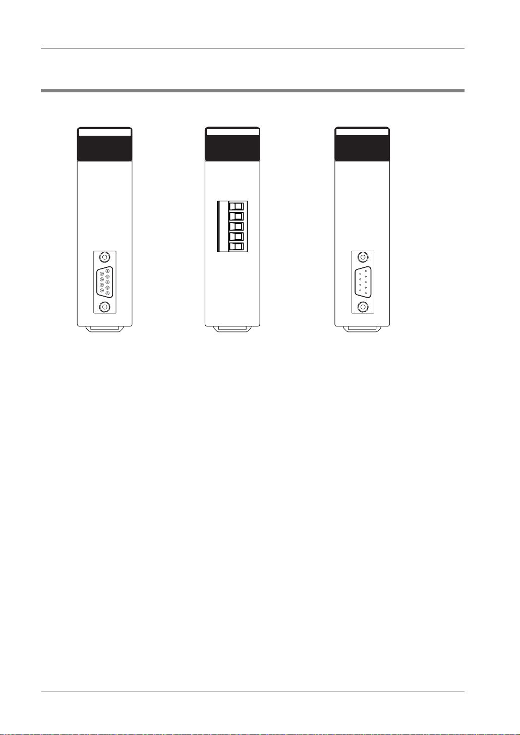
2.1 FP2 FMU
FMU Technical Manual
FP2 PROFIBUS DP Master Unit
FP2-DPV1-M (AFP27971)
DPV1-M
SYS
COM
PROFIBUS
COM. (RS485)
FP2 DeviceNet Master Unit
FP2-DEV-M (AFP27972)
FP2 Fieldbus Master Units, front view
DEV-M
DeviceNet
MNS
COM
FP2 CANopen Master Unit
FP2-CAN-M (AFP27973)
CAN-M
SYS
COM
CANopen
6

FMU Technical Manual
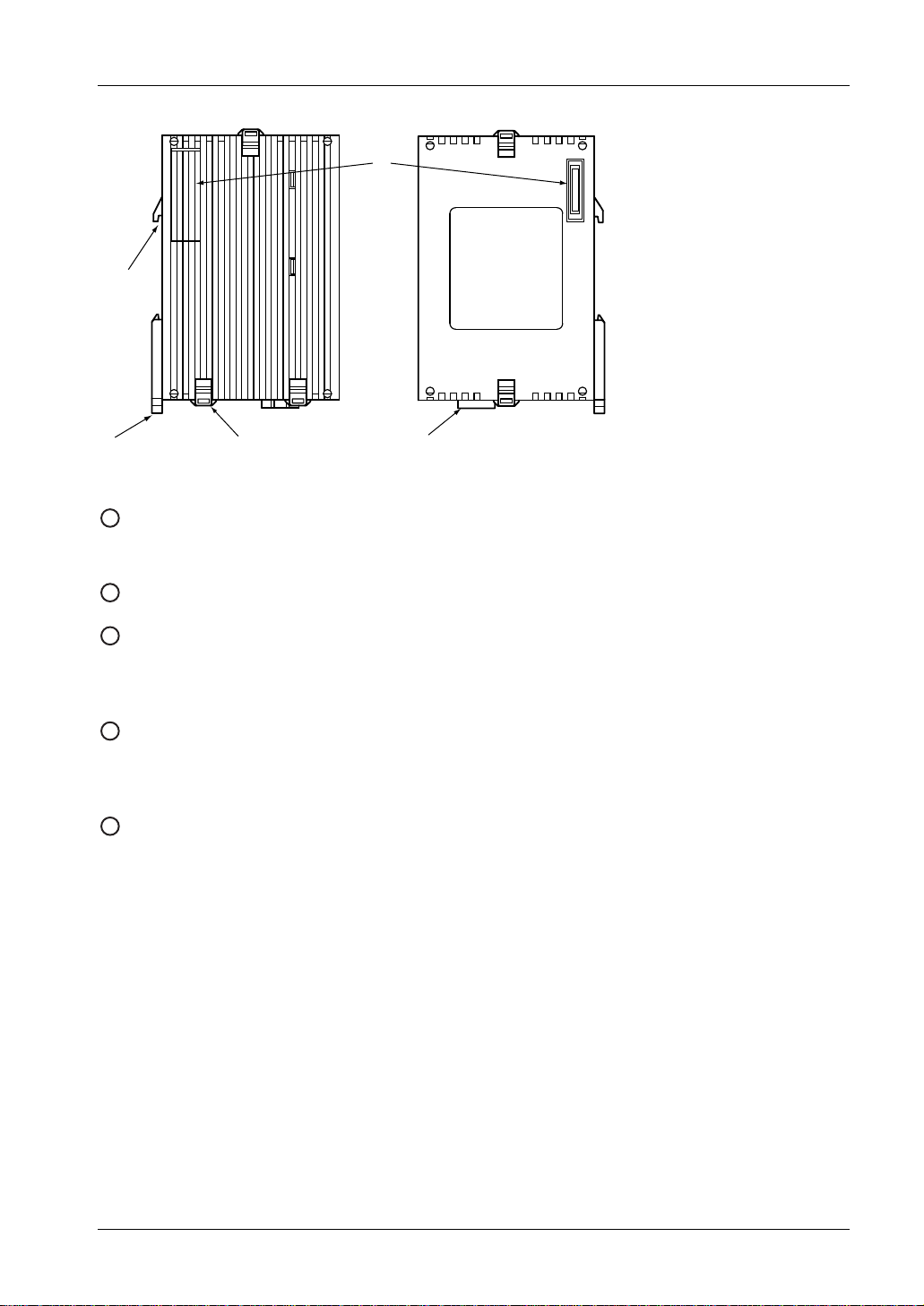
FP2 Fieldbus Master Units, back view, side view on backplane
1
Backplane
1
2
3
4
5
2.1 FP2 FMU
2
DIN rail attachment lever
3
DIN standard rail attachment
4
Connector to the slot on the backplane
5
Expansion hook
7

Parts and Functions
2.2 FPΣ FMU
FMU Technical Manual
FPΣ PROFIBUS DP Master Unit
FPG-DPV1-M (AFPG7971)
PROFIBUS
Master
COM SYS
FPG-DPV1-M
FP
Σ
Fieldbus Master Units, front view
FPΣ DeviceNet Master Unit
FPG-DEV-M (AFPG7972)
DeviceNet
Master
MNS SYS
FPG-DEV-M
FPΣ CANopen Master Unit
FPG-CAN-M (AFPG7973)
CANopen
Master
COM SYS
FPG-CAN-M
8
FMU Technical Manual
2
2.2 FPΣ FMU
1
3
FP
Σ
Fieldbus Master Unit, side views
1
FPΣ expansion connector
54
Used to connect the unit to the control unit or other expansion units.
2
DIN standard rail attachment
3
DIN rail attachment lever
Used for easy attachment to a DIN rail. The lever is also used for installation on the FP0 slim 30
type mounting plate (part no. AFP0811).
4
Expansion hook
Used to secure an expansion unit. The hook is also used for installation on the FP0 flat type
mounting plate (part no. AFP0804).
5
Function earth connector
At least one of the 2 pins must be connected to function earth to achieve proper EMC behavior.
The FPΣ-FMU is connected to the left side of the control unit via the FPΣ expansion connector.
9

Parts and Functions
FMU Technical Manual
2.3 FP-FMU LEDs and Connectors
Various FP Fieldbus Master Units (FMUs) are available to meet your networking needs.
LEDs
Two dual-color LEDs give you a quick overview of the FMU's status at a glance:
• SYS (for DeviceNET MNS). Defines the general status of the FMU. For the hardware,
yellow means the self-test has been passed and the firmware loaded. Green is used for
application oriented functions such as valid configuration loaded.
• COM. Shows communication errors or status and communication activities. See
subsequent sections for details.
SYS/MNS LED
Color State Indication
Off No power.
Yellow
Flashing (1Hz).
ON
ON
FMU is in bootloader mode and is waiting for
firmware download.
Green
0.0 1.00.5
Flashing (5Hz).
ON
OFF
0.0 1.0
Acyclic flashing.
(3 times fast at 5Hz, 8 times between 0.5Hz
and 1Hz.)
For example:
ON
OFF
0.0 1.0
ON. FMU has established at least one configured fieldbus
Flashing (5Hz).
ON
OFF
0.0 1.0
Acyclic flashing.
(3 times fast at 5Hz, 8 times between 0.5Hz
and 1Hz.)
For example:
ON
OFF
0.0 1.0
(s)
2.01.5
Firmware download in progress.
(s)
2.0
Hardware or severe runtime error detected. FMU or
firmware needs replacement. Contact your
Panasonic representative.
. . . 8x
(s)
3.0
connection.
No error in configuration found. The FMU is online
and ready for fieldbus communication, but
connection to a fieldbus device has not been
established.
• Power up. Configuration missing and FMU needs
commissioning.
• Runtime. Firmware has found a critical link
problem, e.g. host watchdog timeout.
. . . 8x
(s)
3.0
2.0
2.0
(s)
2.0
10

FMU Technical Manual
2.3 FP-FMU LEDs and Connectors
2.3.1 FP-PROFIBUS DP
SYS LED (see page 10)
COM LED
Color State Indication
Yellow
Red ON. FMU has detected a communication problem with at least
PROFIBUS connector, DB9F, 9-pin Sub-D female
Connector Pin
9
6
ON. FMU is holding the PROFIBUS token and is able to transmit
Acyclic flashing.
(Between 0.5Hz and 100Hz.)
OFF. FMU is not configured or has not received permission to hold
PROFIBUS telegrams.
FMU is sharing the PROFIBUS token with other master
devices in the PROFIBUS network.
the token in the PROFIBUS network.
one PROFIBUS slave device. Connection timeout.
Signal Description
1
2
3
4
5
6
7
8
9
Housing
5
1
- -
- -
B Line Positive RxD/TxD, RS485 level
RTS Request to send
GND Bus ground (isolated)
+5V bus output (see
note)
- -
A Line Negative RxD/TxD, RS485 level
- -
Cable shield
+5V termination power (isolated)
• FPΣ: Internally connected to the function earth
connector of the FMU.
• FP2: Internally connected to the earth terminal of
the power unit.
NOTE
Any current drawn from pin 6, the +5V bus output pin, will affect the total power
consumption.
11

Parts and Functions
2.3.2 FP-DeviceNet
MNS LED (see page 10)
COM LED
Color State Indication
Green
Red ON FMU cannot access the network.
OFF
ON FMU is operational and online, connections established.
• FMU is allocated to another master.
• FMU has established a connection to a slave.
Flashing (1Hz)
ON
ON
FMU is operational and online, no connection established.
• Configuration missing.
• FMU has passed the duplicate MAC ID check but has not
0.0 1.00.5
(s)
2.01.5
established connection to another device.
• BUS off because of severe CAN faults.
• Duplicate MAC ID detected.
⎯
FMU is not online.
• Duplicate MAC ID test not completed.
• Power may not be supplied.
FMU Technical Manual
DeviceNet Connector
Connector Pin
1
2
3
4
5
5
1
NOTE
Mandatory 24V bus power.
Signal Description
V- Negative bus supply voltage (see note)
CAN_L CAN low bus line
SHIELD Cable shield
CAN_H CAN high bus line
V+ Positive bus supply voltage (see note)
12

FMU Technical Manual
2.3 FP-FMU LEDs and Connectors
2.3.3 FP-CANopen
SYS LED (see page 10)
COM LED
Color State Indication
ON FMU is currently sending a CAN telegram. Yellow
OFF FMU has finished sending a CAN telegram.
Red ON FMU has detected a communication problem with at least one
CANopen Interface
Connector Pin
6
9
1
5
1
2
3
4
5
6
7
8
9
Signal Description
CAN_L CAN low bus line (dominant low)
CAN_GND Negative bus power supply input
CAN_H CAN high bus line (dominant high)
CANopen node device. Connection timout.
13


Chapter 3
Specifications
 Loading...