

Page 1
FD-L45
Glass
substrate
3.8 mm
0.150 in
29 mm
1.142 in
20 mm
0.787 in
Arm
Positioning precision
0.2 mm 0.008 in or less
Sensing object
(glass substrate)
Fiber head
25 mm
0.984 in
10 mm
0.394 in
Alignment
range
Maximum sensing range
30 mm 1.181 in (FAST mode)
Glass substrate
pitch
50 to 60 mm
1.969 to 2.362 in
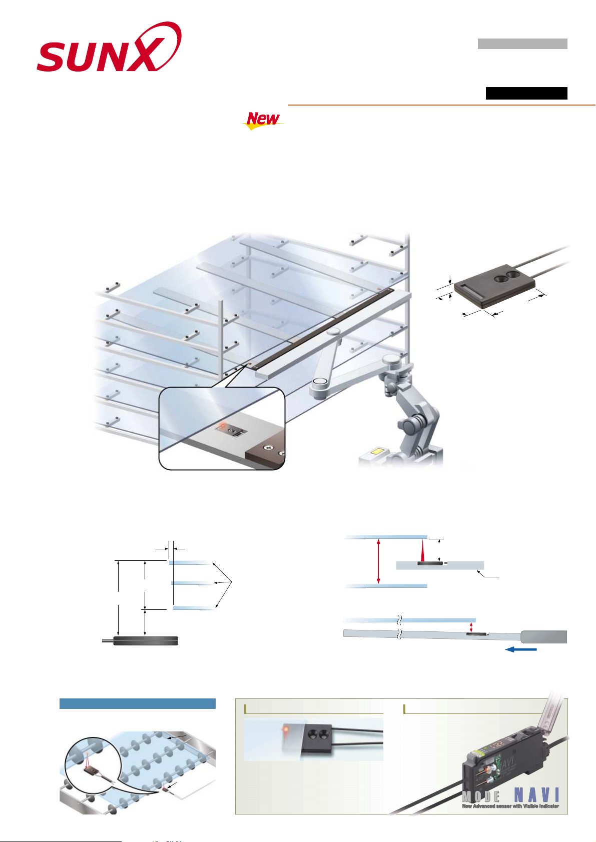
This fiber is perfect for enlarged processing lines constructed to
handle the recent increase in the scale of glass substrates.
Alignment at an even longer range made possible
Ideal for the increasing size of glass substrates
• Fiber cable length 3 m 9.843 ft (Free-cut)
Designed for mounting on large-scale robots
• Alignment possible in FAST mode (150 ¨s)
Throughput is improved thanks to its quick startup.
This fiber has a sensing range of 0 to 30 mm 0 to 1.181 in and an
alignment range of 10 to 25 mm 0.394 to 0.984 in. This wide range of
alignment makes it perfect for large glass substrates. (FAST mode)
Ideal for 6th and beyond
generation large glass substrates
Easy operation
FD-L43 short-range type also available
Sensing range:
0 to 23 mm 0 to 0.906 in (STD mode)
Alignment range: 3 to 17 mm 0.118 to 0.669 in
(Positioning precision 0.2 mm 0.008 in or less)
Angular deviation:
Right and left side inclination
of the sensing object 8
Accurate sensing can also be performed at a long
range for checking objects on a conveyor.
Other application
FX-300 SERIES
A long sensing range =more leeway in the alignment range
• Sensing possible even if the pitch between glass substrates is wide.
• Extended sensing range handy for when large-scale robot arms
bend increasing the distance of the object from the fiber.
New Advanced sensor with Visible Indicator
FD-L45
GLASS SUBSTRATE ALIGNMENT FIBER
OPTICAL FIBER HEAD
Fixed-focus Reflective Type
Page 2
2431-1 Ushiyama-cho, Kasugai-shi, Aichi,
486-0901, Japan
Phone: +81-(0)568-33-7211
FAX: +81-(0)568-33-2631
SUNX Limited
Phone: +81-(0)568-33-7861
FAX: +81-(0)568-33-8591
Overseas Sales Dept.
http://www.sunx.co.jp/
All information is subject to change without prior notice.
No. PCE-FDL45 May, 2004
Beam-emitting
side
Beam-receiving
side
"1.3 "0.0512
3.8
0.150
2-mounting holes for M3
countersunk head screws
6.5
0.256
10
0.394
2.5
0.098
"3.2 "0.126 Model No. tube (PVC)
Beam-emitting /
receiving part
Sensing direction
A
A
Beam-emitting / receiving
fiber core "0.25 "0.0109
View A
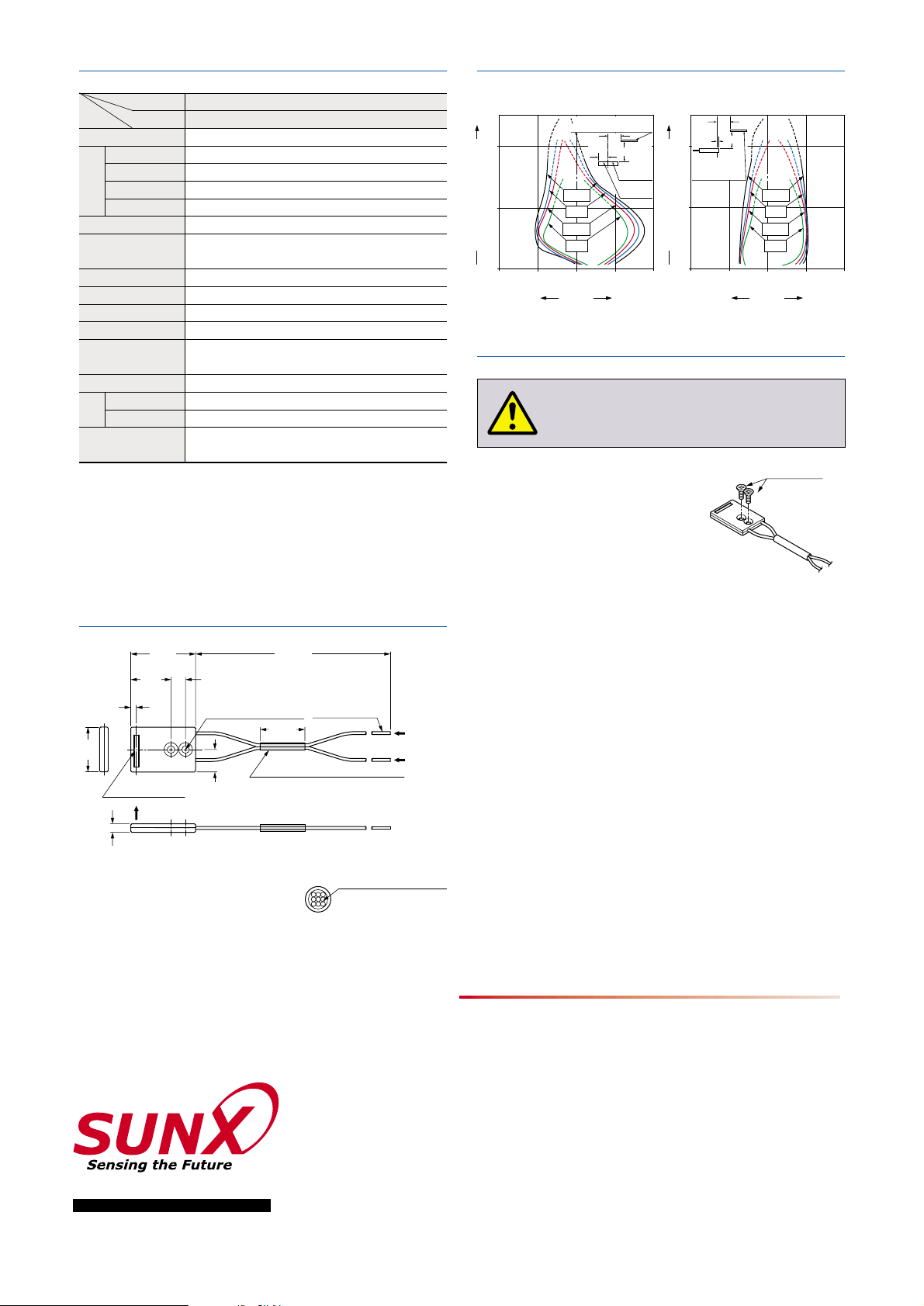
4
0.15720.079
02
0.07940.157
0
20
0.787
40
1.575
LONG
FAST
STD
S-D
Beamemitting part
Beamreceiving part
• Horizontal direction
0
20
0.787
40
1.575
LONG
FAST
STD
S-D
L
2.5 mm
0.098 in
#
• Vertical direction
20
0.787
29
1.142
18
0.709
3,000
118.110
Setting distance L (mm in)
Setting distance L (mm in)
Transparent glass plate (100 100
t 0.7 mm 3.9373.937t 0.028 in)
L
#
10 mm
0.394 in
Left
Right
Center
Operating point ?(mm in)
Transparent glass plate
100
100t 0.7 mm
3.937
3.937t 0.028 in
2
0.07910.039
01
0.03920.079
Down
Up
Center
Operating point ?(mm in)
M3 countersunk
head screws
Please arrange
separately.
)
)
( )
20
0.787
( )
SPECIFICATIONS
SENSING FIELDS (TYPICAL)
Applicable amplifiers (Note 1)
Sensing object
Angular deviation (Note 2)
Position sensing accuracy (Note 2)
Allowable bending radius
Fiber cable length
Bending durability
Ambient temperature
Ambient humidity
LONG
STD
FAST (Note 3)
S-D
Fiber cable
Fiber head
Accessories
Sensing range (Note 2)
Material
Fixed-focus reflective
FD-L45
FX-301(P), FX-311(P)
0 to 36 mm 0 to 1.417 in
0 to 30 mm 0 to 1.181 in
0 to 30 mm 0 to 1.181 in
0 to 21 mm 0 to 0.827 in
LCD glass
0.2 mm 0.008 in or less (at sensing range 10 to 25 mm 0.394 to 0.984 in)
R4 mm R0.157 in or more
3 m 9.843 ft free cut
100,000 times or more (at R4 mm R0.157 in)
35 to 85 % RH, Strage: 35 to 85 % RH
Fiber core: Acrylic, Sheath: Polyethylene
Case: Heat-resistant ABS, Lens: Acrylic
PRECAUTIONS FOR PROPOSER USE
Type
Model No.
Item
0 to70 C 32 to158 F (No dew condensation or
icing allowed), Strage: 0 to
70 C 32 to158 F
Right and left side inclination of the sensing object:
6
(at sensing range 10 to 25 mm 0.394 to 0.984 in)
FX-AT5 (Attachment for "1.3 mm "0.051 in fiber): 1 set
FX-CT2 (Fiber cutter): 1 pc.
Notes: 1)
2)
3)
Refer to the sensor general catalog 2003-2004, catalog of each
amplifier (FX-301/311 series) or SUNX website (http://www.sunx.
co.jp/) for details about the applicable amplifier.
The sensing range, the angular deviation and the position sensing
accuracy are specified for glass substrate (100
100t 0.7 mm
3.937
3.937t 0.028 in) as the object. Furthermore, the
angular deviation and position sensing accuracy are the values for
FAST mode.
FX-311(P) does not have a FAST mode.
DIMENSIONS (Unit : mm in
)
The CAD data in the dimensions can be downloaded
from the SUNX website: http://www.sunx.co.jp/
This product is not a safety sensor. Its use is not
intended or designed to protect life and prev ent body
injury or property damage from dangerous par ts of
machinery. It is a normal object detection sensor.
Mount using M3 countersunk head
screws. The tightening torque should
be 0.3 N m or less.
•
•
•
•
•
•
•
•
•
•
•
Note that the sensing may not be stable if the sensing object is
specially processed, e.g., if light does not reflect regularly on its
surface.
Do not use the fiber at places having intense vibrations, as this
can cause malfunction.
Keep the fiber head surface intact. If it is scratched or spoiled, the
detectability will deteriorate.
If the sensing surface gets dirty, wipe dirt or stains from the
sensing faces with a soft cloth moistened with water. (Do not use
organic solvents.)
Do not expose the fiber to any organic solvents.
Do not use the fiber head surface in places where it may come in
direct contact with water. A water drop on the fiber head surface
deteriorates the sensing. No dew or liquid drop is present on
surface of fiber head or sensing object.
Ensure that any strong extraneous light is not incident on the
receiving face of the fiber head.
Do not apply excessive tensile force to the fiber cable.
Take care that the fiber is not directly exposed to fluorescent light
from a rapid-starter lamp or a high frequency lighting device, as it
may affect the sensing performance.
There is white dots on the beam-emitting fiber cable. When
setting the amplifier, put the fiber cable with white dots into the
beam-emitting side.
Mounting
Cautions
 Loading...