

Page 1
Mapping fiber
FD-L46
Seating confirmation fiber
FD-L44
Alignment fiber
FD-L43
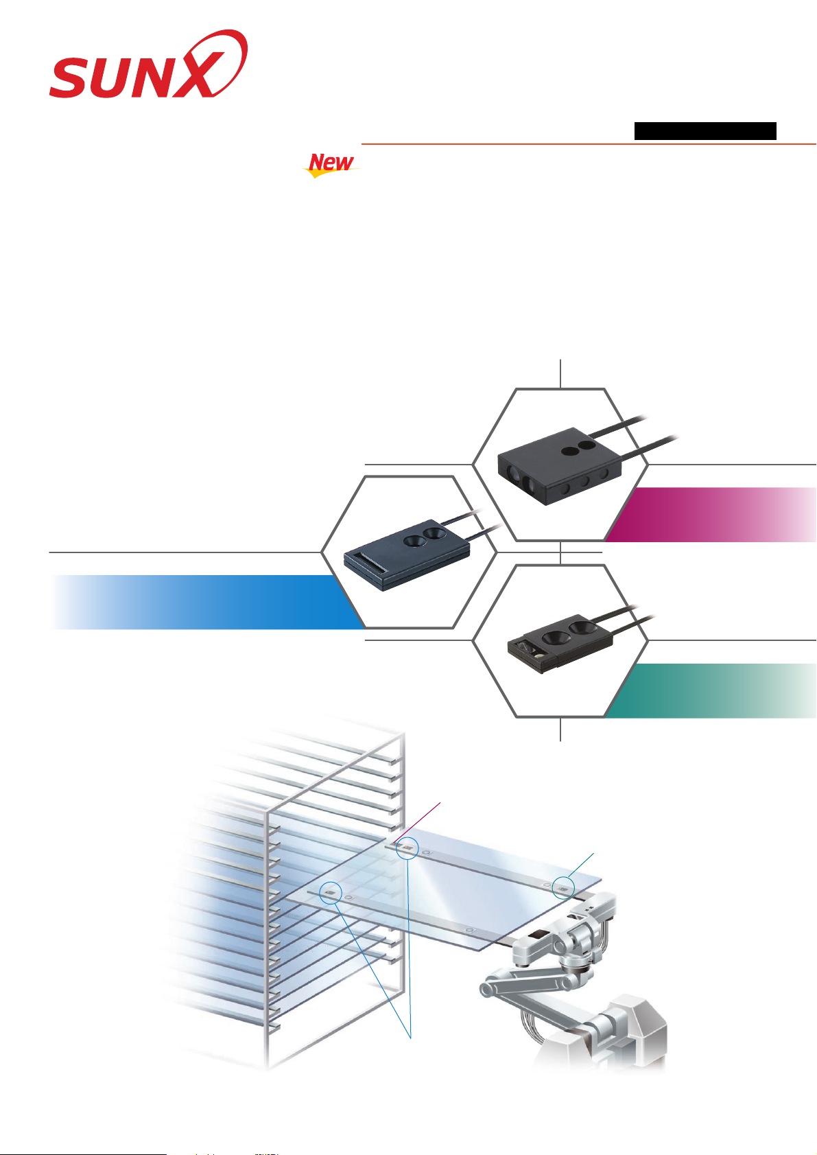
FD-L40SERIES
FIBERS FOR LIQUID CRYSTAL DISPLAY INDUSTRY
3 types of fiber for glass
substrate conveyors
Fixed-focus Reflective Type
Mapping fiber
Alignment fiber
Seating confirmation fiber
Page 2
1 2
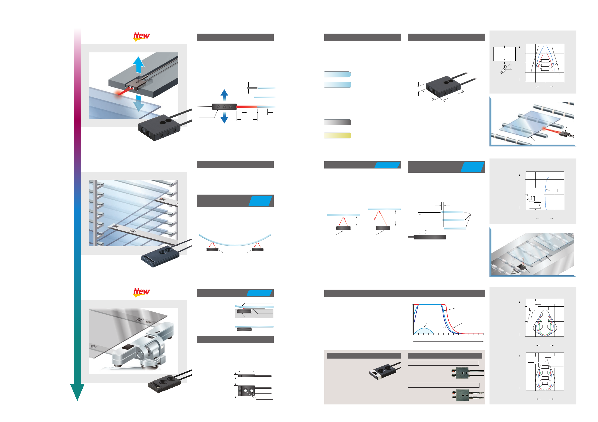
FD-L46
Glass substrate
7.3 mm
0.287 in
25 mm
0.984 in
30 mm
1.181 in
The adoption of a unique large lens allows
even thin glass substrates to be sensed
directly from the side. In addition, because
the sensing range is wide (2512.5 mm
0.9840.492 in), stable mapping is
possible even if glass substrates are in
irregular positions.
Accurate mapping even for thin glass substrates
Minor modifications allow sensing range to
be further increased so that even more
stable and high-precision alignments are
possible.
Increased sensing performance
Increases in sizes of glass substrates
mean greater amounts of flexure, but a
single fiber can sense glass even if
horizontal flexure is within 8 (previously
6).
Large light amounts can be obtained for a
variety of glass edge shapes such as R
surfaces and C surfaces, so that accurate
mapping of glass substrates inside
cassettes is possible.
Glass that has received black or yellow
masking can also be sensed in addition to
clear glass.
Can be used for a variety of glass substrates
A compact size of W25H30D7.3 mm
W0.984H1.181D0.287 in allows
installation to the ends of robotic hands. In
addition, the adoption of a resin case
means weight is light at about 39 g.
Light and compact
Stable sensing is possible over even
longer sensing ranges.
In addition, the fiber will not detect a glass
substrate 30 mm 1.181 in or more away
achieving outstanding detecting
characteristics for limited distance.
Sensing range 0 to 23 mm 0 to 0.906 in
A sensing range of 3 to 17 mm 0.118 to
0.669 in (previously 5 to 17 mm 0.197 to
0.669 in) and a positioning error of 0.2 mm
0.008 in or less makes higher precision
sensing possible.
Longest sensing range
in the industry for
seating confirmation.
Sensing is even
possible if absorption
pads are presented.
Sensing range 0 to 7 mm 0 to 0.276 in
Independent, large-scale lenses is built-in.
Large amounts of light can be received,
enabling stable sensing even of glass
substrates that have been colored (with
low reflectivity) by their treatment
conditions.
Stable sensing of colored glass substrates
Glass substrate sensing
on a roller conveyor
Sensing object (Glass substrate)
Sensing enabled from 0 mm 0 in
Ultra-thin and compact size, so takes up
less space for mounting.
Also, the center of the beam axis and the
center of the mounting hole are directly
aligned rendering system designing simple.
Ultra-thin head with thickness of 3 mm 0.118 in
Sensing object
(Glass substrate)
Fiber
head
Fiber
head
0.2 mm 0.008 in
or less
Fiber head
3 mm 0.118 in
17 mm
0.669 in
Sensing object
(Glass substrate)
Fiber
head
0 to 23 mm
0 to 0.906 in
Sensing object
(Glass substrate)
Fiber
head
30 mm 1.181 in
or more
0.5 mm 0.020 in glass
substrates can also be sensed
12.5 mm
0.492 in
12.5 mm
0.492 in
25 mm
0.984 in
(
At LONG mode
)
Fiber head
R surface
C surface
Black mask
Yellow mask
0 1
0.03920.07930.11840.15750.19760.236
Peak incident light intensity with respect to distance
Distance (mm in)
7
0.27680.31590.354100.394110.433120.472130.512140.551
Conventional seating
confirmation fiber
(Clear glass)
FD-L44
(Chrome film)
FD-L44
(ITO film)
FD-L44
(Clear glass)
SUNX fixed-focus reflective type fibers: The definitive choice for sensing glass substrates
• Horizontal
direction
Anglular deviation
(
Typical
)
Other application
Other application
Positioning characteristics
(
Typical
)
Sensing characteristics (Typical)
• Vertical
direction
FD-L46
Alignment fiber
FD-L43
Seating confirmation fiber
FD-L44
Increased performance
Increased
performance
• •Can sense small glass
substrates with narrow
pitch and wafers.
Same large amounts of
light as the FD-L44 can
be obtained.
Fiber cable length: 2 m 6.562 ft free-cut
Allowable bending radius: R25 mm
R0.984 in or more
Sensing range: 0 to 15 mm 0 to 0.591 in (LONG)
Fiber cable length: 2 m 6.562 ft fixed
Allowable bending radius: R25 mm
R0.984 in or more
Sensing range: 0 to 15 mm 0 to 0.591 in (LONG)
180 C 356 F heat-resistant type / FD-H18-L31
300 C 572 F heat-resistant type / FD-H30-L32
The short range type FD-L44S is also available
Heat-resistant fibers FD-H30-L32, FD-H18-L31 are also available
Fiber head
Absorption pad
$
Fiber head
100 50 0 50 100
0
40
1.575
30
1.181
20
0.787
10
0.394
Left Right
Operating angle $(
)
Center
FAST
1
0.039
0.5
0.020
0 0.5
0.02010.039
0
10
0.394
20
0.787
Operating point ?(mm in)
L
#
Transparent glass
substrate
2.5 mm
0.098 in
Fiber
head
3 mm
0.118 in
19 mm
0.748 in
Beam axis center
12 mm
0.472 in
Mounting holes
STD
L
Glass substrate
100100t0.7 mm
3.9373.937t0.028 in
(R edge)
LONG
STD
Mapping fiber
Setting distance L (mm in)
Does not sense
when the distance is
30 mm 1.181 in or more.
Sensing
object
Glass
substrate
Setting distance L (mm in)
Left Right
Center
2
0.07910.039
01
0.03920.079
0
5
0.197
10
0.394
L
Beamemitting
part
#
6 mm
0.236 in
LONG
FAST
STD
S-D
Transparent glass substrate (100100
t0.7 mm 3.9373.937t0.028 in
)
Left
Right
Center
Operating point ?(mm in)
Beamreceiving
part
2
0.07910.039
01
0.03920.079
0
5
0.197
10
0.394
L
2 mm
0.079 in
#
S-D
FAST
STD
LONG
Transparent glass
substrate
(100100t 0.7 mm
3.9373.937t 0.028 in)
Down
Up
Center
Operating point ?(mm in)
Setting distance L (mm in)
Setting distance L (mm in)
Incident light intensity
Glass substrate
FD-L43
Glass substrate detection
on a conveyor
Different colored glass
can also be sensed
A thickness of just
3 mm 0.118 in !
Stable and greater performance in
sensing of glass with 8 flexure
Edges with poor reflectivity
can also be sensed
Improved high-precision
sensing over wide ranges
Increased
performance
Sensing range: 0 to 4 mm 0 to 0.157 in (at STD mode)
Dimensions: W12
H19D3 mm
W0.472
H0.748D0.118 in
Senses up to 23 mm 0.906 in
(previously : 20 mm 0.787 in)
from seating position.
Longest in the industry
( )
Page 3

2431-1 Ushiyama-cho, Kasugai-shi, Aichi,
486-0901, Japan
Phone: +81-(0)568-33-7211
FAX: +81-(0)568-33-2631
SUNX Limited
Phone: +81-(0)568-33-7861
FAX: +81-(0)568-33-8591
Overseas Sales Dept.
http://www.sunx.co.jp/
All information is subject to change without prior notice.
No. PCE-FDL40 November, 2003
PRECAUTIONS FOR PROPOSER USE
FD-L46
This product is not a safety sensor. Its use is not
intended or designed to protect life and prevent body
injury or property damage from dangerous parts of
machinery. It is a normal object detection sensor.
Mounting
Cautions
Applicable amplifiers (Note 1)
Min. sensing object (Note 4)
Allowable bending radius
Fiber cable length
Ambient temperature
Ambient humidity
Weight
Accessories
FX-301(P), FX-302(P), FX-311(P)
15 to 35 mm 0.591 to 1.378 in
16 to 29 mm 0.63 to 1.142 in
0 to 23mm 0 to 0.906 in 0 to 6 mm 0 to 0.236 in 0 to 4 mm 0 to 0.157 in
12.5 to 37.5 mm 0.492 to 1.476 in 0 to 7 mm 0 to 0.276 in 0 to 4.5 mm 0 to 0.177 in
0 to 3.8 mm 0 to 0.150 in
0 to 3.5 mm 0 to 0.138 in
0 to 5.7 mm 0 to 0.224 in
0 to 5.2 mm 0 to 0.205 in
"0.3 mm "0.012 in gold wire "0.03 mm "0.001 in gold wire
R4 mm R0.157 in or more R10 mm R0.394 in or moreR25 mm R0.984 in or more
2 m 6.562 ft free cut4 m 13.123 ft free cut
40 to 60 C 40 to 140 F,
Strage:
40 to 60 C 40 to 140 F
0 to 70 C 32 to 158 F,
Strage: 0 to
70 C 32 to 158 F
40 to 60 C 40 to 140 F,
Strage:
40 to 60 C 40 to 140 F
35 to 85 %RH (No dew condensation or icing allowed), Strage: 35 to 85 %RH
Case: ABS, Lens: Norbornene resin
Case: Heat-resistant ABS, Lens: Acrylic
Case: Polycarbonate, Lens: Acrylic, Slit mask (FD-L44S only): Stainless steel (SUS304)
39 g Approx. 7.3 g Approx. 5 g Approx.
Fiber core: Acrylic, Sheath: Polyethylene
Item Model No.
Type
FD-L44SFD-L44FD-L43FD-L46
For seating confirmationFor mapping For alignment
Material
LONG
STD
FAST (Note 3)
S-D
Fiber
Fiber head
Sensing range
(Note 2)
FD-L43
FD-L44
FD-L44S
10 0.394
29
1.142
6.5 0.256
18
0.709
3.8
0.150
17 0.669
2.5 0.098
2-mounting holes for M3
countersunk head screws
("3 "0.118) Model No. tube (PVC)
Beam-emitting /
receiving part
Beam-emitting side
Beam-receiving side
"1.3 "0.0152
15
0.591
7.5
0.295
7.5
0.295
"2.2 "0.0872
20
0.787
7.3 0.287
4,000
157.48
(8 0.315)
25
0.984
6.5 0.256
19 0.748
Lens
("3.2 "0.126) Model No. tube (PVC)
2-"3.2 "0.126 mounting holes, "5.7 "0.224 countersinking, 2.6 deep
3 0.118
Beam-emitting fiber
"0.25 "0.0107
Beam-receiving fiber
"0.5 "0.020
View A View B
2.5 0.098
0.8 0.031
8 0.315
Slit mask
Lens
"1
"0.039
2-mounting holes for M3
countersunk head screws
A
B
2,000
78.740
19
0.748
2 0.079
(
"3.2 "0.126) Model No. tube (PVC)
"1.25
"0.049
("3.2 "0.126) Model No. tube (PVC)
8.5 0.335
7
0.276
12
0.472
0.6
0.024
A
2,000
78.740
8 0.315
2.9 0.114
12
0.472
19
0.748
2 0.079
8.5 0.335
7 0.276
Lens
2-mounting holes for M3
countersunk head screws
"1
"0.039
"1.25
"0.049
B
3-"3.2 "0.126 set screw mounting holes (0.5 deep, on both sides)
FD-L44
FD-L44S
SPECIFICATIONS
Notes: 1)
2)
3)
4)
Refer to the sensor general catalog 2003-2004, catalog of each amplifier (FX-301/311 series) or dedicated homepage for fiber sensor (http://www.fiber-sensor.com) for details
about the applicable amplifier.
The values for the FD-L46 are for R edge of glass substrate (100
100t0.7 mm 3.9373.937t0.028 in) for LCDs; the values for the FD-L43 and FD-L44 are for glass
substrate (100
100t0.7 mm 3.9373.937t0.028 in) for LCD, and the values for the FD-L44S are for silicon wafer (polished surfaces).
FX-311(P) does not have a FAST mode.
The minimum sensing object size is the value at maximum sensitivity. Also, note that the corresponding setting distance is different from the rated sensing distance.
20
0.787
DIMENSIONS (Unit : mm in)
( )
( )
Mount using M3 countersunk head screws (FD-L46: M3 pan head
screws. Please arrange separately). The tightening torque should be
0.3 Nm or less (FD-L46: 0.5 Nm or less).
The FD-L46 can be mounted as shown in
the figure at right using M3 set screws
(
Please arrange separately
).
The tightening torque at this time should
be 0.5 Nm or less.
•
•
•
•
•
•
•
•
•
•
•
•
FD-L43: Note that the sensing may not be stable if the sensing
object is specially processed, e.g., if light does not reflect
regularly on its surface.
Do not use the fiber at places having intense vibrations, as this
can cause malfunction.
Keep the fiber head surface intact. If it is scratched or spoiled, the
detectability will deteriorate.
If the sensing surface gets dirty, wipe dirt or stains from the
sensing faces with a soft cloth moistened with water. (Do not use
organic solvents.)
Do not expose the fiber to any organic solvents.
Do not use the fiber head surface in places where it may come in
direct contact with water. A water drop on the fiber head surface
deteriorates the sensing.
Ensure that any strong extraneous light is not incident on the
receiving face of the fiber head.
Do not apply excessive tensile force to the fiber cable.
Take care that the fiber is not directly exposed to fluorescent light
from a rapid-starter lamp or a high frequency lighting device, as it
may affect the sensing performance.
There is white dots (FD-L43) or white line (FD-L44/L44S) on the
beam-emitting fiber cable. When setting the amplifier, put the fiber
cable with white dots into the beam-emitting side.
30
1.181
FX-AT3 (Attachment for "2.2 mm fiber
"0.087 in): 1 set, FX-CT2 (Fiber cutter): 1 pc.
FX-AT5 (Attachment for "1.3 mm fiber
"0.051 in): 1 set, FX-CT2 (Fiber cutter): 1 pc.
FX-AT6 (Attachment for "1 mm "0.039 in /"1.3 mm "0.051 in mixed
fiber): 1 set, FX-CT2 (Fiber cutter): 1 pc.
mThe views A and B and
the side views are the
same for the FD-L44.
2,000 78.740
20
0.787
( )
M3 set
screw
(Cup point)
 Loading...