

Page 1
C M Y K
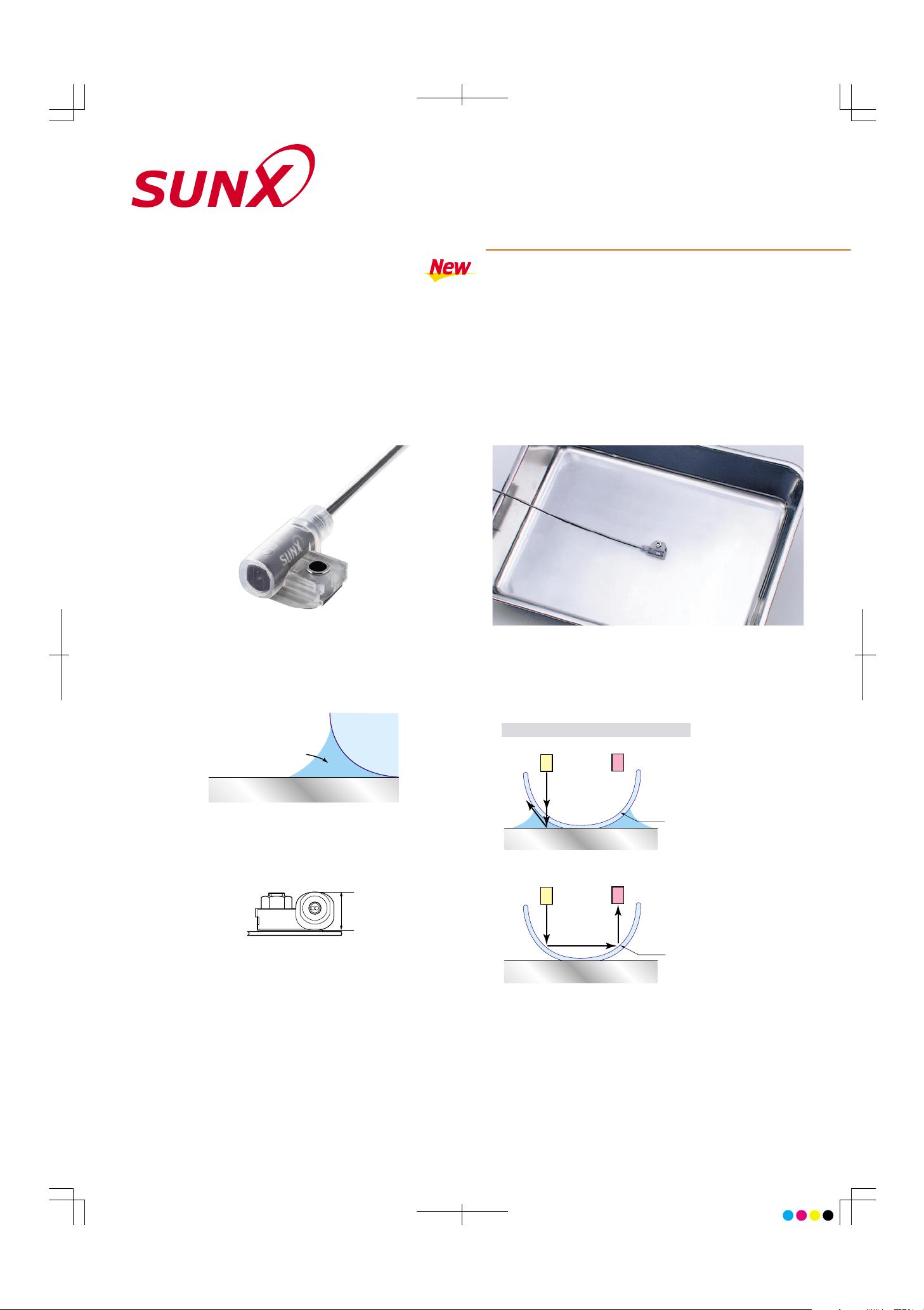
FD-F7SERIES
LEAK FIBER
Reliable Detection
The unique effect of capillarity enables reliable detection of
small leaks and viscous liquids.
Compact, Space-saving
This slim (10mm) side-mounting sensor is especially good for
use in confined spaces.
Simple to Use
•
Bracket mounted with one screw, one-touch fiber head
mounting.
•
No resetting or component replacement required after leak
detection.
•
The simple shape of the fiber head makes it easy to wipe
off the leaked liquid.
Ideal for chemicals and volatile materials
This fiber type sensor is safer to use with volatile materials
(SEMI S2 compliant). The flouride resin fiber head makes it
ideal for use with chemicals.
Stable Design
•
When a leak occurs, the beam from the beam-emitting part
scatters through the leaked liquid and is not transmitted to
the beam-receiving part.
•
If the fiber is bent or faulty, if the cable is cut or disconnected,
or if the sensor is not operating correctly, the output is the
same as when the beam is not received (LEAK).
•
Human error when installing the fiber is also accounted for.
Incorporated Emitting Indicator
The fiber head is equipped with an emitting indicator so that you
can easily check the sensor without having to get close to it.
2 Types of Mounting Brackets Are Available (PFA, PVC)
Capillarity effect
Leakage pan
Liquid
Fiber head
10mm
Beam-emitting part Beam-receiving part
Leakage pan
Leaked liquid
Sensing
surface
New Type of Detection Method
Beam-emitting part Beam-receiving part
Leakage pan
Sensing
surface
A New Slim Fiber Sensor Ideal for
Sensing Chemical Leaks
When leakage occurs
The beam from the beamemitting part scatters through
the leaked liquid and is not
transmitted to the beam-receiving part.
When there is no leakage
The beam from the beamemitting part reflects off of
the surface of the sensor and
is transmitted to the beam-receiving part.
Page 2
C M Y K
SPECIFICATIONS PRECAUTIONS FOR PROPER USE
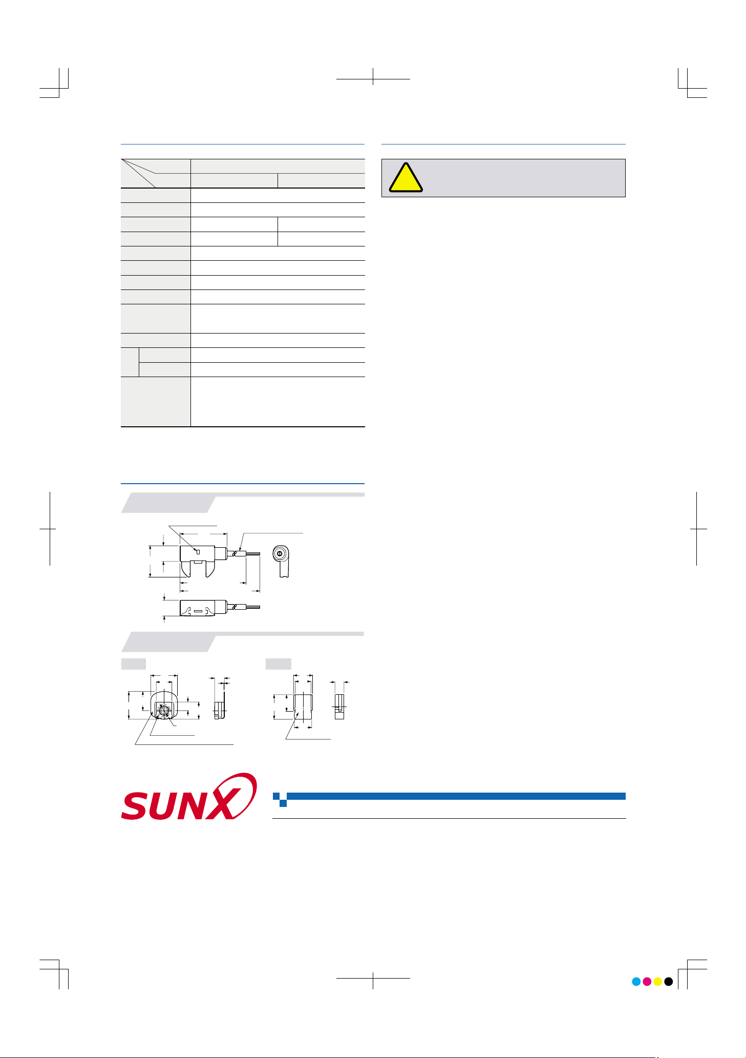
DIMENSIONS (Unit: mm)
Notes: 1) Highly viscous liquid may not be detected stably.
2) Liquid being detected should also be kept within the rated ambient temperature range.
20
3,000 (FD-F707: 5,000)
5,000 (FD-F707: 7,000)
10
30
10
Emitting indicator
(
"3.1 protective tube)
·
There is a white stripe on the beam-emitting fiber cable. When setting the
amplifier, put the fiber cable with white stripe into the beam-emitting side.
The sensor will not operate correctly if the emitter and receiver are not
connected correctly.
·
Do not scratch and spoil the fiber head surface. If it is scratched or
spoiled, the detectability will deteriorate.
When conducting maintenance after operation, wipe all liquid from the
fiber head and mounting bracket with a soft cloth.
·
Do not apply excessive tensile force to the fiber cable.
·
Bending radius of the fiber cable must be R4mm or more. If the bending
radius is smaller than the specified value, the sensing performance may
deteriorate.
·
Ensure that any strong extraneous light is not incident on the receiving
face of the fiber head.
·
The fiber cable can be cut for adjustment using the attached fiber cutter,
however, the performance of the sensor may greatly decrease depending
the condition of the cut fiber cable and the connection to the amplifier.
·
Shortening the fiber cable excessively may result in loss of reliable detection due to an insufficient light intensity difference. (As a reference, adjust
the length of the fiber cable so that the amplifier reads 4,000, or less, when
mounted using the exclusive mounting bracket and without any liquid.)
·
Be sure to use the exclusive mounting bracket when installing the sensor
to avoid human error. Reliable detection cannot be guaranteed when this
mounting bracket is not used.
·
Do not scratch the fiber sheath while cutting the protective tube.
·
Be sure to adjust the sensitivity of the amplifier after mounting the fiber
head in the mounting bracket and completing layout and wiring the fiber
cable in actual working conditions. Perform the same sensitivity adjustment after changes in layout or installation for maintenance, etc. Changes
in layout or installation after completing sensitivity adjustment may result
in the loss of reliable detection due to the change of incident light intensity.
·
Note that the light intensity may greatly decrease when used under high
temperature and high humidity for long periods.
!
This product is not a safety sensor. Its use is not intended
or designed to protect life and prevent body injury or
property damage from dangerous parts of machinery. It is
a normal object detection sensor.
Cautions
Designation
Model No.
Item
Applicable amplifier
Sensing object
Protective tube length
Fiber cable length
Allowable bending radius
Bending durability
Emitting indicator
Peel strength
Ambient temperature
Ambient humidity
Accessories
FX-D1-F
Liquid (Note 1)
Protective tube: R20mm or more, Fiber cable: R4mm or more
Fiber cable: 1,000,000 times or more (at R4mm)
Incorporated
19.6N or less (PFA protective tube)
− 20 to + 60°C (No dew condensation or icing allowed),
Storage: − 20 to + 60°C (Note 2)
35 to 85% RH, Storage: 35 to 85% RH
Fiber core: Acrylic, Fiber sheath: Vinyl chloride, Protective tube: PFA
Outer casing: PFA, Interior: Heat-resistant ABS, Acrylic, Brass
PFA mounting bracket: 1 No.
PVC mounting bracket: 1 No.
FX-CT1 (Fiber cutter): 1 No.
FX-AT10 ("1mm fiber attachment): 1 set
3m
5m free-cut
5m
7m free-cut
FD-F705 FD-F707
Leak fiber
Fiber cable
Fiber head
Material
FD-F705
FD-F707
Fiber
Maunting bracket
PFA PVC
4.2 thru-hole
11
5.5
0.3
10
17.7
12.2
17
6.2
Material: PFA
Material: Stainless steel (SUS316)
5.7
10.5
15.5
12
10
11
Material: PVC
Set the sensitivity of the FX-D1-F amplifier using the ‘Limit teaching’
function as described below.
1
Set the fiber head in the exclusive mounting bracket and layout
and wire the fiber cable in actual working conditions.
2Set the mode selection switch to either ‘RUN’ or ‘MODE’.
3
Set to either Output 1 or Output 2 by turning the jog switch to the
‘+’ or the ‘−’ side.
4
Set the mode selection switch to ‘SET’ the present threshold value is displayed.
5
Press the jog switch in the liquid absent condition and release it
within 3 sec.
6
The read incident light intensity is displayed for 0.5 sec. approx.
Subsequently, ‘2nd’ is displayed on the LCD display.
7
Turn the jog switch to the ‘−’ side. ‘good’ is displayed on the
LCD display.
8
Set the mode selection switch to ‘RUN’, and setting is completed.
Amplifier setting procedure
No. CE-FDF7-5 January, 2001
2431-1 Ushiyama-cho, Kasugai-shi, Aichi, 486-0901, Japan
Phone: +81-(0)568-33-7211
FAX: +81-(0)568-33-2631
SUNX Limited
Phone: +81-(0)568-33-7861
FAX: +81-(0)568-33-8591
Overseas Sales Dept.
Printed on 100% recycled paper
PRINTED IN JAPAN
http://www.sunx.co.jp/
All information is subject to change without prior notice.
 Loading...