

Page 1
Instruction
Manual
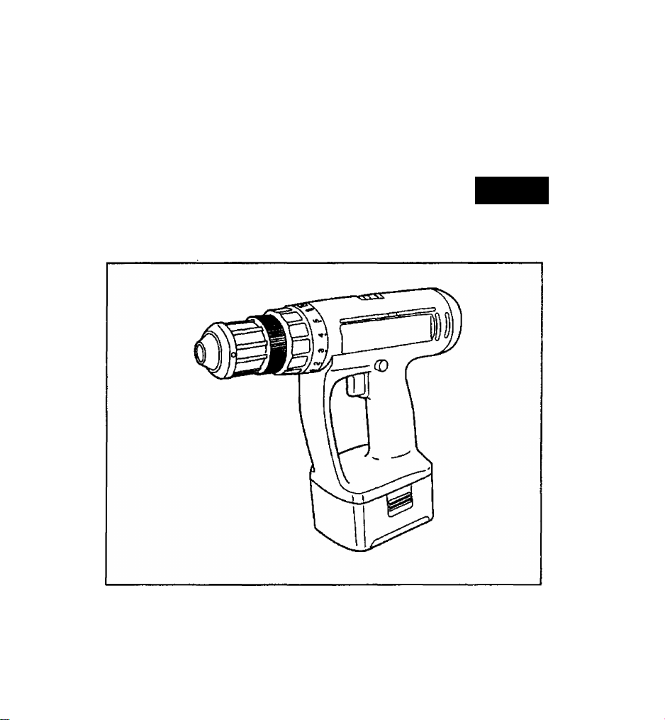
Hammer Drill & Driver
Cordless
EY6930
Panasonic s.
Before operating this unit, please read these Instructions completely.
Page 2

MP OR TA NT SA FE TY
NS TR UC TI ON S
WARNING: When using electric
tools, basic safety precautions should
always be followed to reduce the risk of
fire, electric shock and personal injury,
including the following:
READ ALL INSTRUCTIONS
BEFORE USING
1) KEEP WORK AREA
CLEAN. Cluttered areas and
benches invite accidents.
2) CONSIDER WORK AREA
ENVIRONMENT. Do not expose
power tools to rain. Do not use power
tools in damp or wet locations. Keep work
area well lit Do not use tooi in presence
of flammatHe Hquids or gases.
3) GUARD AGAINST
ELECTRIC SHOCK.
Prevent body contact with grounded
surfaces. For exampie; pipes, radia
tors, ranges, refrigerator enclosures.
4) KEEP CHILDREN AWAY.
Do not let visitors contact tool. All ^nsitors
should be kept away from work area.
5) STORE IDLE TOOLS.
When not in use, tools should be
stored in a dry, high or locked-up
piaoe — out of reach of chiidren.
6) DON’T FORCE TOOL.
It wili do the job better and safer at
the rate for which it was designed.
7) USE RIGHT TOOL.
Don’t force smalt tools or attachments
to do the job of a heavy duty toot.
Don’t use tool for purpose not Intended-for example-don’t use circular saw
for cutting tree limbs or logs.
8) WEAR PROPER
APPAREL. No loose Clothing or
jewelry to get caught in moving parts.
Rubber gloves and nonskid footwear are rec
ommended when working outdoors. Wear
protective hair covering to contain long hair.
9) USE SAFETY GLASSES
with most tools. Also use face or
dust mask in dusty environment.
10) SECURE WORK, use
clamps or a vise to hold work. It's
safer than using your hand and it
frees both hands to operate tool.
11) DON’T OVERREACH.
Keep proper footing and balance at all
times.
12) MAINTAIN TOOLS
WITH CARE. Keep tools sharp
at all bmes and clean for best and safest
performance. Follow instructions for
lubricating and changing accessories.
Keep handles dry, dean and free from oil
and grease.
13) DISCONNECT TOOLS/
BATTERIES. When not in
use, before servicing, and when
changing accessories, such as bits.
14) REMOVE ADJUSTING
KEYS AND WRENCHES.
Form a habit of checking to see that
keys and adjusting wrenches are
removed from tool before turning it on.
15) AVOID ACCIDENTAL
STARTING. Don't carry tool
with finger on switch.
16) STAY ALERT.
Watdi what you are doing. Use common
sense. Do not operate tool when you are
tired.
17) CHECK DAMAGED
PARTS. Before further use of the
tools, check guard or other safety
devices carefulty to determine that they
will operate property and perform their
intended function. Check for aKgnment
of moving parts, binding of moving
parts, breakage of parts, rrKXjnting, and
any other conditions that may affect its
operation. A guard or other part that is
damaged should be property repaired
or replaced by an aufoorized service
center. Have defective parts replaced
by an authorized service center. Do not
use a defective fool.
SAVE THESE INSTRUCTIONS
-2-
Page 3

FO R BA H E R Y CH A R G
ER & B A H E R Y P A C K
1) SA VE T HE SE I N
ST RU CT IO NS - ™s
manual contains Important safety and
operating instructions for battery
charger EY0212 and EY0213.
2) Before using battery charger, read all
instructions and cautionary markings
on (1) battery charger, (2) battery
pack.
3) CAUTION -To reduce the risk
of injury, charge only Battery Pack
shown bellow.
EY0212
EY0213
EY0213 EY9230
Other types of batteries may burst
causing personal injury and damage.
4) Do not expose charger to rain or
snow.
5) To reduce risk of damaging the elec
tric plug and cord, pull ^ plug rather
than cord when disconnecting charg
er.
6) Make sure cord is located so that it
will not be stepped on, tripped over,
or otherwise subjected to damage or
stress.
7) An extension cord should not be
used unless absolutely necessary.
Use of improper extension cord could
result in a risk of fire and electric
shock, if extension cord must be
used, make sure:
a. that pins on plug of extension cord
b. that extension cord is properly
c. that wire size is large enough for
EY9103, EY9101.EY9001,
EY9006, EY9180, EY9080,
EY9182, EY9086, EY9065,
EY9106, EY9107, EY9136,
EY9117
are the same number, size and
shape as those of plug on charg
er.
wired and in good electrical condi
tion.
ampere rating of charger as speci
fied below.
RECOMMENDED MINIMUM AWG SIZE OF
EXTENSION CORDS FOR
BATTERY CHARGERS
AC Input Rating. Amparw
Equal to or But toss
grebter than than
0 2
8) Do not operate charger with dam
aged cord or plug—replace them
immediately.
9) Do not operate charger if It has
received a sharp blow, been dropped,
or otherwise damaged in any way;
take it to a qualified serviceman.
10) Do not disassemble charger; take it
to a qualified serviceman when ser
vice or repair is required. Incorrect
reassembly may result in a risk of
electric shock or ftre.
11) To reduce the risk of electric shock,
unplug charger from outlet before
attempting any maintenance or
cleaning.
12) The charger and battery pack are
specifically designed to wo^ togeth
er. Do not attempt to charge any
other cordless tool or battery pack
wi№ this charger.
13) Do not attempt to diarge the battery
pack with any oUier charger.
14) Do not attempt to disassemble the
battery pack housing.
15) Do not store the tool and battery
pack in locations where the tempera
ture may reach or exceed 122*’F
(50*'C) (such a metal tool shed, or a
car In the summer), which can lead to
deterioration of the storage battery.
16) Do not charge battery pack when the
temperature is BELOW 32“F (0"C) or
ABOVE 104*F (40"C). This Is very
important.
17) Do not incinerate the battery pack. It
can explode In a fire.
18) Avoid ^ngerous environment. Do not
use charger in damp or wet locations.
19) The charger is designed to operate
on standard household electrical
power only. Do not attempt to use it
on any other voltaget
20) Do not abuse cord. Never carry
charger by cord or yank it to discon
nect from outlet. Keep cord away
from heat, oil and sharp edges.
21) Charge the battery pack in a welt
ventilated place, do not cover the
charger and battery pack with a doth,
etc., while charging.
3-
AWG Size of Cord
Langdi of Cord, Feat
25 50 100 150
18 18 18 16
Page 4

22) Use of an attachment not recom
mended may result in a risk of fire,
electric shock, or injury to persons.
23) Do not short the battery pack. A bat
tery short can cause a large current
flow, over heating and burns.
24) NOTE: If the supply cord of this appli
ance is damaged, it must only be
replaced by a repair shop appointed
by the manufacturer, because special
purpose tools are required.
25) TO REDUCE THE RISK OF ELEC
TRIC SHOCK, THIS APPLIANCE HAS
A POLARIZED PLUG (ONE BLADE IS
WIDER THAN THE OTHER).
This plug will fit in a polarized outlet
only one way. If the plug does not fit
fully in the outlet, reverse the plug. If
it still does not fit, contact a qualified
electrician to install the proper outlet.
Do not change the plug in any way.
7) When storing or carrying the tool, set
the reversing lever to the center
(switch lock) position.
8) Do not strain the tool by holding the
. speed control trigger halfway (speed
control mode) so that the motor stops.
9) Do not operate the speed selector
switch (LOW-HIGH) while pulling on
the speed control trigger. This can
cause the rechargeable battery to
wear quickly or damage the internal
mechanism of the motor.
Changes or modifications not
expressly approved by
MATSUSHITA ELECTRIC WORKS,
LTD. could void the user’s authority
to operate the equipment.
ADDITIONAL
SAFETY RULES
1) Be aware that this tool is always in
an operating condition, since it does
not have to be plugged into an elec
trical outlet.
2) When drilling or driving into walls,
floors, etc., “live" electrical wires may
be encountered. DO NOT TOUCH
THE CHUCK OR ANY FRONT
METAL PARTS OF THE TOOL! Hold
the tool only by the plastic handle to
prevent electric shock in case you
drill or drive into a “live” wire.
3) If the bit becomes jammed, immedi
ately turn the main switch off to pre
vent an overload which can damage
the battery pack or motor. Use
reverse motion to loosen jammed bits.
4) Do not operate the reversing lever
when the main switch is on. The bat
tery will discharge rapidly and dam
age to the unit may occur.
5) During charging, the charger may
become slightly warm. This is nor
mal. Do not charge the battery for a
long period.
6) Use only a dry, soft cloth for wiping
the unit. Do not use a damp cloth,
thinner, benzine, or other volatile sol
vents for cleaning.
IMPORTANT NOTICE
PLEASE READ THIS ENTIRE
NOTICE BEFORE OPERATING .
. YOUR NEW PANASONIC
CORDLESS POWER TOOU
PANASONIC’S CHARGING
SYSTEM UTILIZES A QUALITY HIGH
TEMPERATURE NICKEL CADMIUM
BATTERY PACK IN CONJUNCTION,
WITH OUR SELF-DIAGNOSTIC
UNIVERSAL INVERTER CHARGER; ^
'THIS HIGH TEMPERATURE NICKEC
CADMIUM BATTERY PACK ; v:/''
REQUIRES A "BREAK-IN PERIOD"..
TO REACH MAXIMUM OPERAVNG
CAPACITY. THE ^ ■
“BREAK-IN PERIOD” IS
ACCOMPUSHED DURING NORMAL
USAGE DURING THE FIRST 6-8
CHARGE AND DISCHARGE
CYCLES OF THE BATTERY PACK.;;^
AFTER THE "BREAK-IN PERIOD" IS
COMPLETED, THE BATTERY PACK
WILL MAINTAIN MAXIMUM ù: ;
OPERATING CAPACITY
THROUGHOUT THE NORMAL UFE‘ '
, Of THE BATTERY PACK. . ,
_4_
Page 5

©
-5-
Keyless drill chuck
Clutch handle
Reversing lever
©
Variable speed control trigger
®
Speed selector switch
(1)
Battery pack (EY9136mY9230)
©
Battery pack release button
Battery charger (EY0212/EY0213)
Lock release rod
©
Page 6

PARTIDENTIRCAT10N
(S) Keyless drill chuck
Note; When attaching or removing a
bit, be sure to set the reversing
lever to its center position
(switch lock).
This tool is equipped with a keyless
drill chuck.
1. Attachment
Insert the bit and turn the k>ck col
lar clockwise ( looking from the
front) to tighten firmly.
Slide the Lock collar to LOCK side.
Lock collar
(To prevent accidental operation,
remove the battery pack before trying
to remove the bit.)
Note; If excessive play occurs in the
chuck, (D secure the drill in place
and tighten the chuck by turning
clockwise, d) open the chuck
daws by unscrewing the lock col
lar and (d tighten the screw (lefthanded screw) with a screwdriver
by turning it counterclockwise
(viewed horn the front).
®
®i
2. Removal
Slide the Lock collar to FREE side.
Turn the lock collar counterclock
wise (looking from the front), then
remove the Ut. , ,
Lock collar
®FREE
Note: If the bit cannot be removed by
hand, insert the lock release
rod or a similar tool into the
hole located on the chuck to
release the lock, and then turn
the lock collar counterclock
wise (viewed from the front).
Chuck
Clutch Handle (Clutch Torque Setting)
Adjust the torque to one of the 5 pos
sible settings to the job.
CAUTION: Test the setting before
Reference for Adjusting Torque
Seal«
Approx. 1.0 Nm
1
(10 kof-cm or 8.7 in-l».)
Approx. 1.5 Nm
2
(15 kgl-cm or 13.0 irt-IbB.)
Approx, 2,6 Nm
3
(25 kgf-cm OT21.7 In-lbs.)
Approx. 3.4 Nm
4
(35 kgf-cm or 30.4 in-lbs.)
Approx. 4.4 Nm
5
(45 kgf-cm or 38.0 tn-lbs.)
19.6 Nm 200kgf-cm,
qa
173.4 in-Kw. (Low speed)
r
actual operation.
Set the scale at this line
Torque
Percussion
Rk driving
terminal screws
For driving
machine screws
For driving Mrews
irttosoflfflUwlBls
For driving
hardwood
Forpoweiftjl
driving mddriHng
For drWng to mor
tar, brick etc.
Use
-6-
Page 7

Bit-locking function
1. With the trlg^r switch not engag^
and a screwdriver bit locked in
piace, and the tool can be used as
a manual screwdriver (up to
22.5Nm, 230kg-cm, 199in-lbs.).
There will be a little play in the
chuck, but this is not a malfunction.
2. This feature is handy for tightening
screws that require more torque
than the maximum torque of the
driver (position csi on the dutch),
for confirming the tightness of a
screw or to loosen an extremely
tight screw.
Reversing lever
©
(Forward (0).Switch lock,Revofse O))
CAUTION: Release the trigger
1. For reverse rotation, set the lever
to reverse. Check the direction of
rotation before use.
2. After use, set the lever at the cen
ter (switch lock) position.
switch to OFF and wait
until the bit has come to
a complete stop before
operating this lever.
Variable apeed control trigger
1. The speed increases with the
amount of depression of the trig
ger. When beginning work, de
press the trigger slightly to start
the motion slowly.
2. A feedback electronic controller is
used to give a strong torque even
In low spi^.
3. The brake operates when the trig
ger is released and the motor
stops immediately.
Note: When the brake operates, a
braking sound may be heard.
This is normal.
© Speed selector switch
Choose a low or high speed to suit
the use.
The more the speed control trigger is
, pulled, the higher the speed.
CAUTION: Check the sp^ selection
before operatirtg this tool.
© Battery pack (EY9136/EY9230)
1. Press the battery pack release
buttons ® on both sides and pull
the pack away from the toot.
2. Charge the battery pack using the
battery charger.
3. After the charging has been com
pleted, remove the battery pack
from the charger and connect it to
the tool. Disconnect the charger
from the A.C. outlet when not in
use.
CAUTION: When operating with a Ni-MH
battery pack (EY9230) make
sure the place is wellventilated.
Battery Pack Life
The rechargeable batteries have a limited
life. If the operation time becomes
extremely short after recharging, replace
the battery pack with a new one.
ATTENTION (EY9136 ONLY):
The nickel cadmium battery you have
purchased is recyclable. At the end of Ifs
useful life, under various state and local
laws, it is illeg^ to dispose of this battery
into your municipal waste stream. Please
call 1-800-8-BATTERY for information on
how to recycle this battery.
© Battery pack release button
-7-
Page 8

0
Battery charger (EY0212/EY0213)
Note: When you charge the battery
pack for the first time, or after
prolonged storage, charge it
for about 24 hours to bring the
batteries up to full capacity.
1. Plug the charger into an AC outlet.
2. Open the cap and Insert the bat
tery pack firmly .ip|oth^p^ai^r.
To AC
outlet
Battery
pack
Battery
charger
• When charging, cooling fan In the
charger functions to cool down the
battery pack, and the sound of fan
can be heard. This is normal. If this
sound cannot be heard, it Is a
malfunction. Stop charging
immediately and consult an
authorized dealer.
3. During charging, the charging
lamp wilt be lit.
When charging is completed, an
internal electronic switch will auto
matically be triggered to prevent
overchcuging.
• Charging will not start if the bat
tery расж is warm <for example,
immediately after heavy-auty
operation), the orange standby
lamp will be lit until the battery
cools down. Charging wilt then
begin automatically.
4. When charging is completed, the
charging lamp will start flashing
rapidly.
5. When in any of the conditions that
the charger is too warm, battery
pack is too cool, or the battery
pack has not been used for a long
time, the charging lamp starts
flashing slowly to indicate protec
tive charging. Protective charging
takes longer to fully charge the
battery pack, than the standard
charging time.
(Max. charging time is approx. 90
minutes.)
• If a fully charged battery pack is
inserted into the charger again,
the charging tamp may light up
and then flash slowly. After sever
al minutes, the charging lamp
may flash quickly to indicate the
charging is completed.
6. If tfie charging tamp does not light
immediately after the charger is
plugged in, or if after the standard
charging time the lamp does not go
off, conduit an authorized dealer.
Note: • When charging a cool battery
pad( (below 5**C) in a warm place,
leave the battery pack at the place
and wait for more than orre hour to
warm up the battery to the level of
the ambient temperatore. (Battery
pack may not be fully charged.)
• Cool down the charger when
charging more than two battery
packs consecutively.
CAUTION: «Do not use power source
from an engine generator.
• Do not cover vent holes on
the charger and the battery
pack.
LAMP INDICATION
Charger is plugged into a wall outlet.
Ready to charge.
] Now charging
Charging Is completed
— CZ3 Protective charging
Battery pack is warm. Charging will begin
when temperature ol battery (wck drope.
Charging is not possible. Clogged with
duet or malfunction o( the battery peck.
-8-
Page 9

SPECIFICATIONS
Body EY6930
EYe930FQKW EY6930NQKW
Capability
Screw
drtvirtg
Drilling
Machine screw
Wood screw
Mortal Brick 1 ^3'«^13mm(1/8"-i/27' ' ' ‘ '■
Wood
Steal
jM3,5^M6
j ^2.1'-^6.8mm(5/64''-17/64*)
j ^3'-^27mm(1/8*'--1-1/32')
1 ^1,5-'^13mm(1/16'"-1/2‘)
Motor DC Motor 15.6V
No-load
Speed
Blows rate
per minute
Low
■
IH^
Low
i
nt^ 4050'^3000(Vmln(rpm)
70''-57(Vmin(rpm)
270'-2000/min(rpm)
105085S(Vmin(fpm)
Chuck capacity 1,5mm ~ 13mm(1 /16"~ 1 /2*)
22.5Nm(230kgf-om or 199ln-lbs)
5.9Nm(60kgf-cm or 52in-lbs}
Max. Torque
Low
t
rUgn
Blow strength 6.9Nm(70kgf-cm or 61 in-lbs)
Overall length
WelQht
(with Battery PadQ
2.36kg,(5.2 lbs)
263mm(10-1/64")
2.45kg,(5.4 lbs)
Battey Pack EY9136
EY9230
Storage Battery
Battery voltage
Nl-Cd battery
15.6V DC (1.2V X 13ceils)
Battery Charger EY0212
Weight
Charging time
EY0212
EY0213
EYQ213
1,4kg,(3.1 lbs)
2.4V
16.6V 12V
—
—
EY9117
EY9136
—
EY8230
Ni-MH battery
EY0213
1.3kg,(2.9 lbs)
9.6V 7ÆV
EY9001
—
EY9006
EY9101
—
EY9103
EY9106
EY0107
-9-
EY9080
EY9066
EY9180
EY9162
—
— —
EY9065
—
—
—
Approx. 20 min.
Approx. 25 min.
Approx. 30 mki.
Approx. 46 min.
 Loading...