

Page 1
ORDER NO.PTD0606U32CE
F16
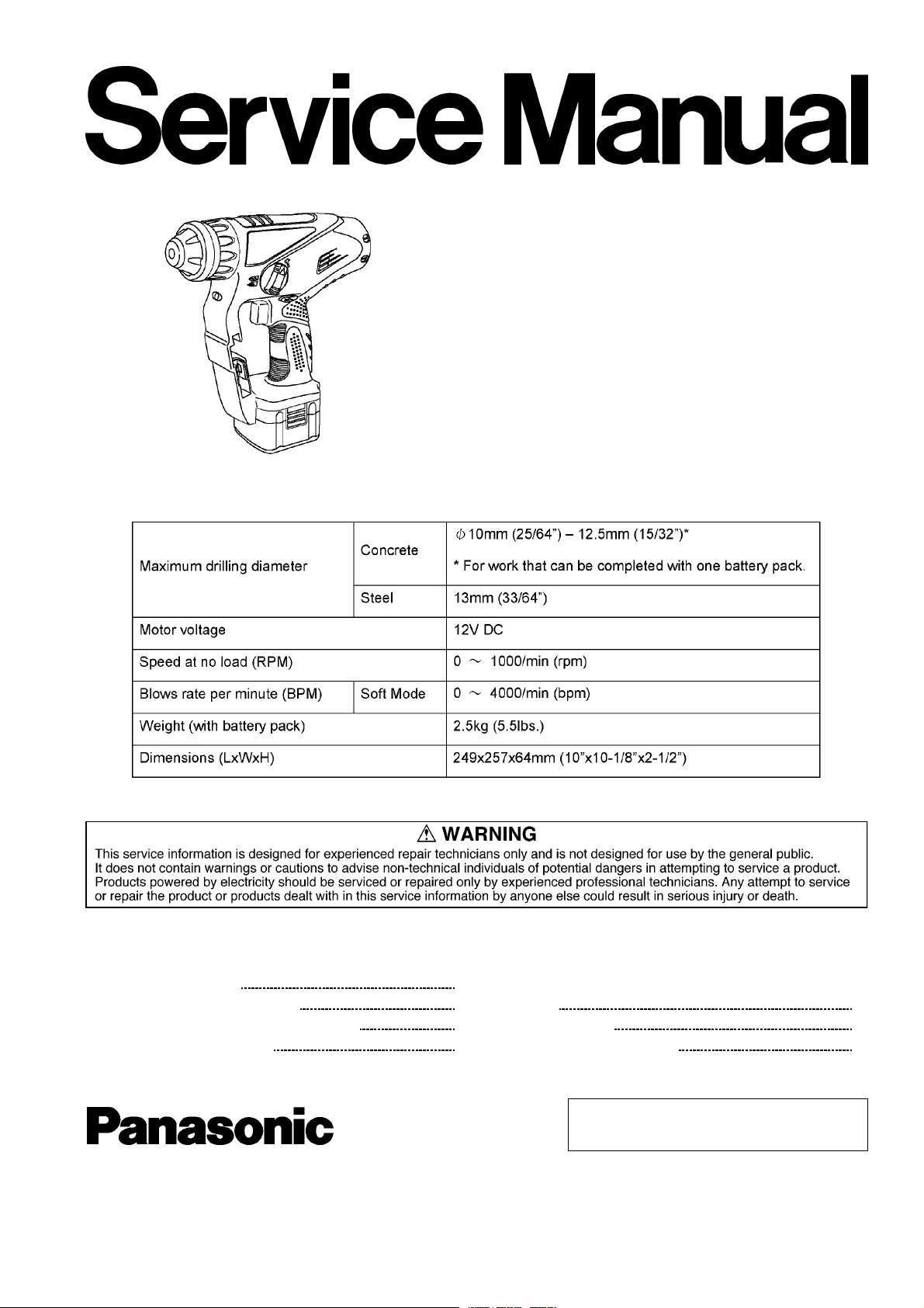
Cordless Rotary Hammer Drill & Driver
EY6803-U1
SPECIFICATIONS
CONTENTS
Page Page
1 SCHEMATIC DIAGRAM 2
2 WIRING CONNECTION DIAGRAM
3 DISASSEMBLY/ASSEMBLY INSTRUCTIONS
4 TROUBLESHOOTING GUIDE
5 TRIAL OPERATION (after checking TROUBLESHOOTING
2
3
7
GUIDE.)
6 EXPLODED VIEW
7 REPLACEMENT PARTS LIST
10
11
12
© 2006 Matsushita Electric Works Ltd. All rights
reserved. Unauthorized copying and distribution is a
violation of law.
Page 2
EY6803-U1
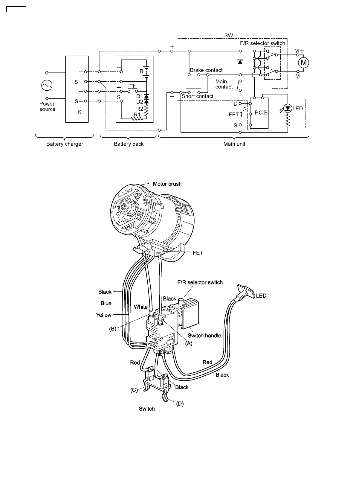
1 SCHEMATIC DIAGRAM
2 WIRING CONNECTION DIAGRAM
2
Page 3

3 DISASSEMBLY/ASSEMBLY INSTRUCTIONS
■HOW TO DISASSEMBLE THE MAIN UNIT.
Ref. No. 1A Procedure 1A Removal of the chuck handle.
1. Set the hammering/drilling switching lever to the position .
2. Pluck the chuck cover depressin g the chuck handle.
3. Remove the chuck handle.
4. Take out a steel ball pushing the chuck spring with the chuck
spring plate.
5. Remove the chuck spring plate and the chuck spring.
EY6803-U1
Ref. No. 1B Procedure 1A→→→→1B Removal of the housing.
1. Remove 14 housing screws.
3
Page 4
EY6803-U1
■HOW TO DISASSEMBLE THE MOTOR AND SWITCH.
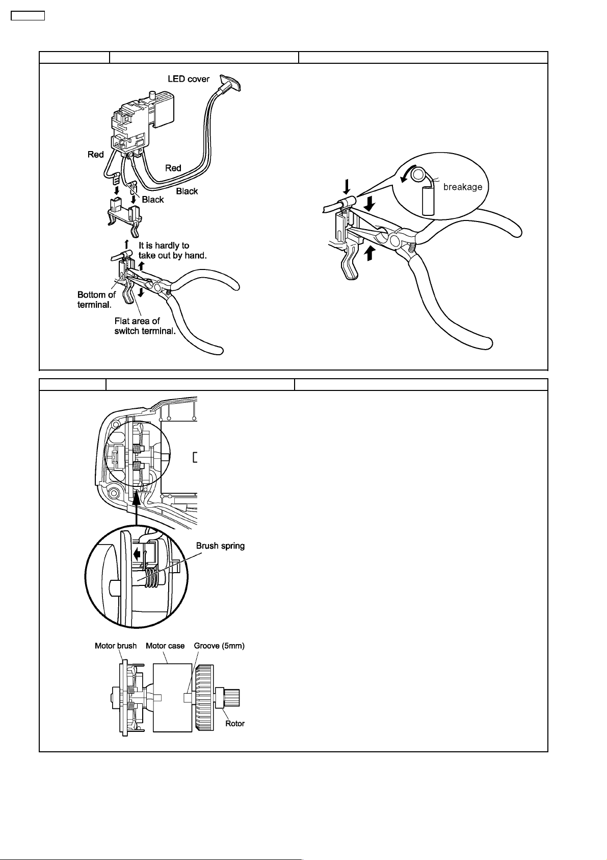
Ref. No. 2A Procedure 1A→→→→1B→→→→2A Removal of the switch.
1. Take out the switch and the base plate assembly from the
housing.
2. Take out the LED cover.
For assembling
NOTE:
Do not push the area where marked the arrow in order to
prevent the breakakge.
Ref. No. 2B Procedure 1A→→→→1B→→→→2A→→→→2B Removal of the motor assembly.
1. Hitch the brush spring to the frame by something like a forceps and
take the motor brush assembly with the switch out from the motor
assembly.
2. Take out the rotor and the current plate from the motor case.
For assembling
NOTE:
Make sure to return the spring into the groove of the motor brush.
Make sure to set the 5mm of groove of motor case on the
hammer side.
Close the housing and try to apply the DC12V and check if the
motor rotates or not.
4
Page 5

■HOW TO DISASSEMBLE THE DRIVING BLOCK.
Ref. No. 2C Procedure 2A →→→→ 2B →→→→ 2C Removal of the power shaft assembly.
1. Remove the piston applying power spring.
2. Take out the power shaft assembly.
3. Remove the c-type ring, felt and snap ring.
4. Remove the clutch handle with pins and the thrust plate.
5. Remove the snap ring.
6. Slide the jig (plate) into between the washer and the gear case
and hold it by a vise.
7. Tap the top of spindle block with a plastic hammer to take out
the spindle and clutch block assembly.
8. Take out the snap ring on the rear side of the bearing.
9. Take out two pins by using absorption force about 30N magnet
from the clutch block.
10. Take out four steel balls and remove the spindle & piston
assembly.
11. Remove the striker with the O-ring and the O-ring. And take out
the bearing.
12. Take out the piston block. And take out the piston and the
universal coupling.
13. Remove the intermediate shaft assembly.
EY6803-U1
5
Page 6

EY6803-U1
Ref. No. 2D Procedure 2A →→→→ 2B →→→→ 2C→→→→ 2D Attachment of driving block.
For assembling
1. Set the jig (bearing cap) into the clutch case and hold it with a
vise in order to take out the bearing.
2. Assemble the bearing with the spindle assembly.
3. Set the snap ring.
NOTE :
It has own direction for reassembly. Place the rounded face of
snap ring to the clutch case side.
4. Fit O-ring onto the bearing.
5. Assemble the chuck spring and the chuck spring plate.
6. Insert a ball pushing down the chuck spring.
7. Insert the reciprocation bearing shaft into the hole of universal
coupling. Make sure two thrust plates should be set both side of
reciprocation bearing shaft one of each.
NOTE :
Apply grease especially for the connection area between
reciprocation bearing and universal coupling. In addition,
hammer O-ring, inside of piston and cylinder for output shaft
block also need to apply.
Air compressed by the piston drives hammer. Take care to
protect the piston and hamme r from contamination by dust.
6
Page 7

4 TROUBLESHOOTING GUIDE
(Refer to WIRING CONNECTION DIAGRAM)
4.1. CHECK POINTS FOR ELECTRICAL PARTS.
EY6803-U1
7
Page 8

EY6803-U1
4.2. CHECK POINTS FOR MECHANISM BLOCK.
8
Page 9

EY6803-U1
9
Page 10

EY6803-U1
5 TRIAL OPERATION (after checking TROUBLESHOOTING
GUIDE.)
5.1. HAMMER/DRILL
Confirm the action when setting the H/D handle to HAMMER mode.
Rotation with hammer ing when the drill bit touches something like stone, and power.
It is OK, if it takes about 4-6 seconds by 20kgf to hole (
Confirm the action when setting the H/D handle to DRILL mode.
No hammering when the drill bit touches iron plate.
5.2. SWITCH
<SPEED CONTROL>
Change the rotation speed from 0-1000 rpm in proportion to the amount of pushing level on switch trigger.
<LED>
Check if the LED is lits.
5.3. REVERSING LEVER
6X30) on the concrete .
Confirm the action with setting the reversing lever to FORWARD or REVERSE.
5.4. ASSEMBLY
Confirm pressing the lead wires between ribs, tightening screws firmly.
10
Page 11

6 EXPLODED VIEW
EY6803-U1
11
Page 12

EY6803-U1
7 REPLACEMENT PARTS LIST
NOTE:
*B=only available as set
*C=available individually
Ref.No. Part No. Part Name & Description Remarks Per Unit
1 WEY6803K3078 HOUSING AB SET 1
2 WEY6813H3117 CHUCK COVER 1
3 WEY6803K3127 CHUCK HANDLE 1
4 WEY6813L0427 BALL GUIDE 1
5 WEY6813L0437 CHUCK SPRING STRIKE PLATE 1
6 WEY6813L1917 STEEL BALL 7 1
7 WEY6813L0917 CHUCK SPRING 1
8 WEY6803L3997 SEAL A 1
9 WEY6803L3987 SEAL B 1
10 WEY6803L0927 PISTON APPLYING POWER SPRING 1
11 WEY6803Y3247 F/R HANDLE 1
12 WEY6803L1167 C-TYPE RING 1
13 WEY6803L3137 FELT 1
14 WEY6803L0467 SNAP RING 1
15 WEY6803L1707 LOCK PIN *B (2PCS/PK) 2
16 WEY6803Y3227 CLUTCH HANDLE 1
17 WEY6803Y3297 CLUTCH CASE 1
18 WEY6813L4957 BEARING 1
19 WEY6803L0477 SNAP RING 1
20 WEY6803L4067 SPINDLE ASSEMBLY 1
21 WEY6803L0057 SPINDLE 1
22 WEY6813L1927 STEEL BALL *B 5, (6PCS/PK) 4
23 WEY6813L0347 O RING 1
24 WEY6803L1237 STRIKER 1
25 WEY6813L0327 O RING 1
26 WEY6813L0317 O RING 1
27 WEY6803L4907 CLUTCH ASSEMBLY 1
28 WEY6813L0907 PIN *B 5x4 (2PCS/PK) 2
29 WEY6813L0477 SNAP RING 1
30 WEY6803L0857 THRUST PLATE *C 2
31 WEY6803L1247 PISTON ASSEMBLY 1
32 WEY6803L4627 HAMMER 1
33 WEY6803L0977 O RING 1
34 WEY6803L1987 PISTON 1
35 WEY6812L0847 THRUST PLATE *B (2PCS/PK) 2
36 WEY6803L1257 UNIVERSAL COUPLING 1
37 WEY6803L0387 NEEDLE BEARING 1
38 WEY6803L4057 INTERMEDIATE SHAFT ASSEMBLY 1
39 WEY6803L1467 MOTOR ROTOR ASSEMBLY 1
40 WEY6803L1187 MOTOR STATOR ASSEMBLY 1
41 WEY6803L2307 MOTOR BRUSH ASSEMBLY 1
42 WEY6803L2007 SWITCH ASSEMBLY 1
43 WEY6803L2017 SWITCH 1
44 WEY6803L2337 LED COVER 1
45 WEY6803L0417 BASE PLATE BLOCK 1
46 WEY6803L2407 TERMINAL BLOCK 1
47 WEY6813L3137 TRIGGER COVER 1
48 WEY6261B6027 SEMS SCREW *C K3-6 2
49 WEY6230K9218 TORX TAPPING SCREW *C K3X20 14
50 WEY6803L0137 CUSHION RUBBER 1
51 WEY3561L3417 SHOULDER STRAP 1
52 WEY6803L4538 POWER SHAFT ASSEMBLY 1
- WEY6811X5537 GREASE ASG-22 1
- WEY6812T7918 GREASE 1
- WEY9629K7018 TOOL CASE 1
- WEY6803K4968 JIG (PLATE & CAP) 1
- WEY6803K8108 OPERATING INSTRUCTIONS 1
** Battery Pack and Bit Adaptor are available as an optional accessory. .
See the nearest sales dealer for details.
*** For replacement parts of charger, see the charger service manual.
Charger complete set is available as an optional accessory. See the nearest sales dealer for details.
12
 Loading...