

Page 1
Cordless Multi Drill & Driver
EY6535-U1
ORDER NO. PTD0108U32C1
F16
SPECIFICATIONS
© 2001 Matsushita Electric Works Ltd. All rights
reserved. Unauthorized copying and distribution is a
violation of law.
Page 2

EY6535-U1
CONTENTS
Page Page
1 SCHEMATIC DIAGRAM 2
2 WIRING CONNECTION DIAGRAM
3 DISASSEMBLY INSTRUCTIONS
4 ASSEMBLY INSTRUCTIONS
5 TROUBLESHOOTING GUIDE
2
6 EXPLODED VIEW
7 REPLACEMENT PARTS LIST
3
6
1 SCHEMATIC DIAGRAM
10
12
13
2 WIRING CONNECTION DIAGRAM
2
Page 3

3 DISASSEMBLY INSTRUCTIONS
■HOW TO DISASSEMBL E THE MAIN UNIT.
Ref. No. 1A Procedure 1A Removal of Fixation Cover and Housing.
1. Remove 4 screws tightened with the fixation
cover and take it out.
2. Remove clutch handle, slider and anvil.
3. Remove 7 housing screws.
4. Remove the click springs and separate
housing A and B.
EY6535-U1
Ref. No. 1B Procedure 1A →→→→ 1B Disassembly of Motor and Gear Box
Block.
1. Remove the motor assembly with the gear box
block from the housing.
2. Separate the motor assembly from the gear
box block by twisting the motor to unlock tabs.
3
Page 4
EY6535-U1
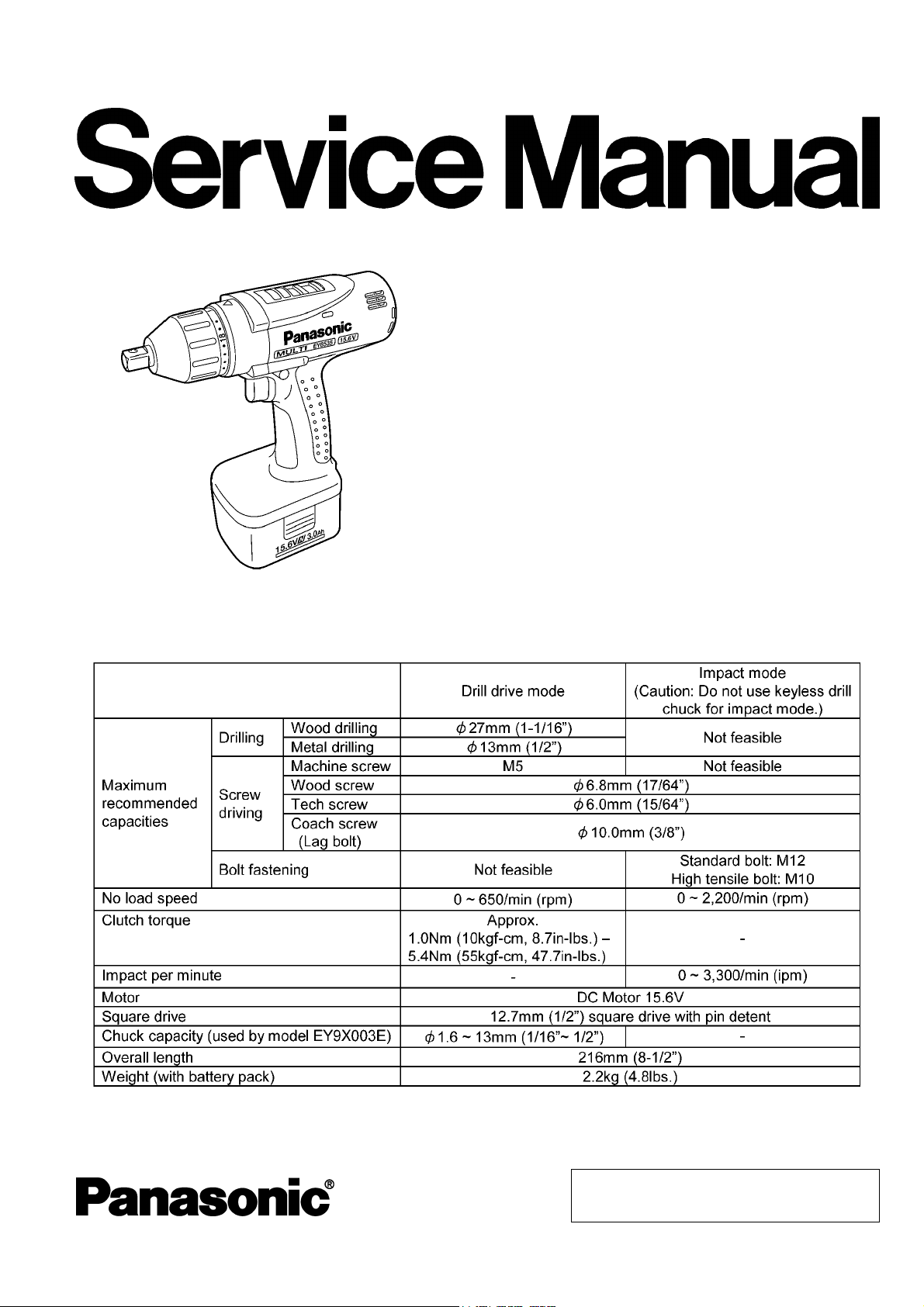
Ref. No. 1C Procedure 1A →→→→ 1B →→→→ 1C Removal of Motor Mounting Base.
1. To remove the ring gear, unhook right and left
side of the projections using a flat screwdriver.
2. After removing the ring gear, the internal parts
can be remove one after another.
3. Loosen 3 screws tightened with the motor
mounting base.
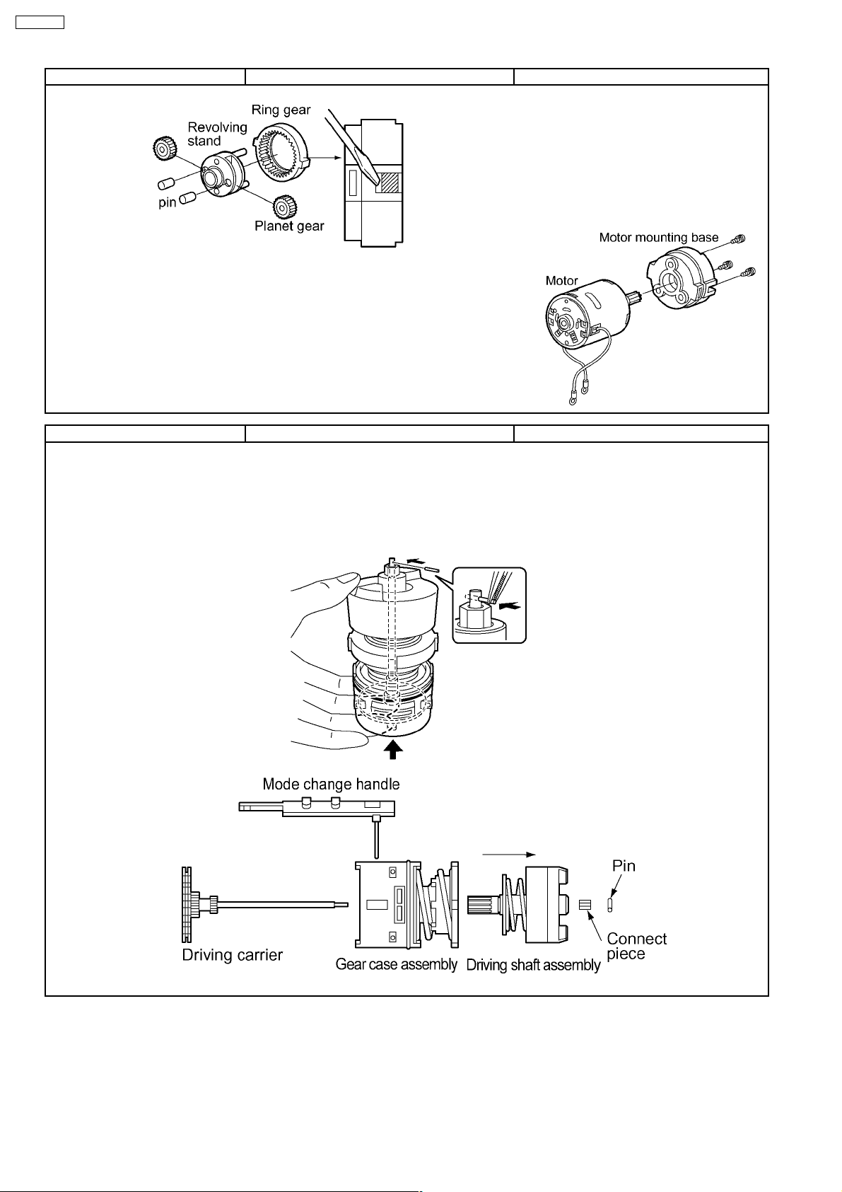
Ref. No. 1D Procedure 1A →→→→ 1B →→→→ 1D Removal of Gear Box Assembly.
1. Hold the driving carrier as illustrated.
Compress the assembly and remove the pin.
2. Take out the driving shaft assembly and the
gear case assembly from the shaft of the driving
carrier.
NOTE :
Make sure not to lose the pin and the
connect piece.
4
Page 5

Ref.No.1E Procedure 1A →→→→ 1B →→→→ 1D →→→→ 1E Removal of Gear Case Assembly.
1. Take out the mode change handle.
2. Pull out 2 pins (
3. After removing pins, the internal parts of the
gear case assembly can be removed one after
another.
thrust plate → clutch gear → planet gear (3pcs)
→ carrier → thrust plate
4. Remove adjusting screw, clutch spring, and
clutch plate.
5. After removing the clutch plate, 6 pieces of
steel ball come off.
2.5×33.6).
EY6535-U1
5
Page 6

EY6535-U1
4 ASSEMBLY INSTRUCTIONS
Ref.No.2A Procedure 2A Assembly of Gear Case Block.
1. Assemble thrust plate, clutch gear, planet gear
(3pcs), carrier, thrust plate and insert pins (2pcs).
2. Reinstall one piece of steel ball into each of 6
holes.
3. Assemble clutch plate and clutch spring.
4. Align the widest protrusion of adjusting screw
with the narrower protrusion of gear case.
5. Turn the adjusting screw into the gear case
assembly one rotation for clockwise direction.
6. Set the mode change handle on the wider
protrusion of gear case.
7. Confirm proper position of the mode change
handle that both ends of spring must be put into
the grooves of the driving carrier.
6
Page 7

Ref.No.2B Procedure 2A→→→→2B Assembly of Motor Mounting Base.
NOTE :
After loosening these screws, please replace
them with new screws. The old screws have
an adhesive that can not be reapplied. New
screws are identified with blue adhesive.
1. Tighten 3 screws of the motor mounting base.
2. Assemble planet gears and pins with the
revolving stand and insert them into the motor
mounting base.
3. The ring gear has its own correct direction.
Confirm the direction when the ring gear is
inserted into the motor mounting base.
4. Adjust the protrusion parts of ring gear with
the groove parts of motor mounting base.
EY6535-U1
7
Page 8

EY6535-U1
Ref.No.2C Procedure 2A→→→→2B→→→→2C Assembly of Gear Box Assembly.
1. Fit the driving carrier into the hole of the gear
case assembly and the driving shaft assembly.
2. Confirm the connect piece is inside of the
driving shaft block.
3. Insert the pin into the shaft of the driving
carrier holding the bottom of the gear box
assembly (driving carrier) by hand.
4. Align the wider protrusion of motor mounting
base with the wider protrusion of gear case.
Ref.No.2D Procedure 2A→→→→2B→→→→2C→→→→2D Assembly of Motor and Switch.
1. Fit terminal of lead wire (black) parallel to the
heat sink.
Caution:
Be careful that the heat sink and the terminal
do not touch, otherwise these are
shortcuircuit.
8
Page 9

Ref.No.2E Procedure 2A→→→→2B→→→→2C→→→→2D→→→→2E Assembly of Housing.
1. Confirm proper position of the click springs
and the position in each housing A and B.
2. Check that the widest protrusion (6mm) of
adjusting screw is in the middle and the mode
change handle is set to the IMPACT position.
3. Set anvil and slider, has its own correct
direction. Confirm the direction when assembling.
4. Set the clutch handle with position 1 on top.
5. When setting fixation cover, align
top.
6. Tighten 4 screws.
EY6535-U1
mark on
9
Page 10

EY6535-U1
5 TROUBLESHOOTING GUIDE
(Refer to WIRING CONNECTION DIAGRAM)
< TROUBLE > < CHECK > < REMEDY >
Does not operate. <CHECK BATTERY PACK.> NO Replace battery pack.
→
If no less than 15.6 V DC is available across the (+) and (-) terminals,
the battery pack is OK.
NOTE:
<CHECK TERMINAL CONNECTIONS BETWEEN MAIN UNIT NO Clean and repair
Check for proper terminal contacts.
The battery pack is sold separately as an optional accessory.
See the nearest sales dealer for details. The battery pack has a
limited life.
The pack should be replaced if;
- after being charged for the rated charging time the battery voltage
is less than 15.6V DC or the usable time is extremely short.
- the battery leaks. Check battery for leaks and terminals for
corrosion.
↓OK
↓OK
AND BATTERY PACK.>
→
→
contacts.
<CHECK SWITCH BLOCK.> NO Contacts in switch block
See WIRING CONNECTIO N DIAGRAM.
Check continuity between following terminals. Replace switch & FET
* Inspection of the forward / reverse selection switch. block.
When switch handle is depressed all the way:
- There should be 0Ω between - , and between - ;
when switch lever is set to forward side.
- There should be 0Ω between - , and between - ;
when switch lever is set to reverse side.
* Inspection of the brake.
When switch handle is not depressed:
- There should be 0Ω between - .
↓OK
<CHECK MOTOR.> NO Replace motor.
The motor normally operates with its white (+) and black (-) lead wires
connected to 15.6V DC.
→
are defective.
→
10
Page 11

< TROUBLE > < CHECK > < REMEDY >
No speed-control. <CHECK FET.> NO Replace switch & FET
→
Even if FET block is defective, it can not be replaced individually. Replace
→
block.
whole switch block.
Shortcircuit (G: gate) and (S: source), and measure between it and (D:
drain) with switch block.
NOTE:
* FET is sensitive against static electricity.
** The resistance value will vary dependent upon the measurement
range of the tester.
↓OK
EY6535-U1
<CHECK SWITCH BLOCK.> NO Replace switch & FET
→
block.
Weakness of <CHECK ANVIL.> NO Replace anvil.
vibration.
→
Check wear condition. If no less than 1mm from the corner at (A) side or
→
0.5mm from the corner at (B) side, anvil is OK.
↓OK
<CHECK HAMMER BLOCK.> NO Replace driving shaft
Check whether hammer block rotates smoothly when moving shaft of
→
assembly.
hammer.
↓OK
<CHECK MOTOR.> NO Replace motor.
Measure no load rotation whether it is more than 1,900rpm with full charged
battery pack.
11
→
Page 12

EY6535-U1
6 EXPLODED VIEW
12
Page 13

7 REPLACEMENT PARTS LIST
NOTE:
*A = available as an optional accessory
*B = only available as set
*C = available individually
Ref. No. Part No. Part Name & Description Remarks Per Unit
1 WEY6535K3078 HOUSING AB SET 1
2 EY6481L0177 CLICK SPRING 1
3 WEY6535K9158 SCREW *C 4×25 4
4 WEY6535S0648 FIXATION COVER 1
5 WEY6535K3748 CLUTCH HANDLE 1
6 WEY6535L0868 SLIDER 1
7 WEY6535L1128 POWER SHAFT 1
8 WEY6535L0888 CONNECT PIECE 1
9 WEY6535L1418 DRIVING SHAFT ASSEMBLY 1
10 WEY6535L0638 ADJUSTING SCREW 1
11 WEY6535L0168 CLUTCH SPRING 1
12 WEY6535L0578 CLUTCH PLATE 1
13 WEY6535L6968 STEEL BALL *B 5 ,(6PCS/PACK) 6
14 WEY6535L1068 GEAR CASE 1
15 EY6481L0357 THRUST PIN 2.5*33.6 *B 2.5×33.6,(2PCS/PACK) 2
16 WEY6535L0928 THRUST PLATE 1
17 WEY6535L1648 CARRIER 1
18 WEY6505L1347 PLANET GEAR *B (3PCS/PACK) 3
19 WEY6535L1358 CLUTCH GEAR 1
20 WEY6535L0908 THRUST PLATE 1
21 WEY6535L0918 PIN 1×5.5 1
22 WEY6535L1368 DRIVING CARRIER 1
23 WEY6505L1457 RING GEAR 1
24 WEY6505L1377 PLANET GEAR A *B (2PCS/PACK) 2
25 WEY6535L1388 REVOLVING STAND 1
26 WEY6505L0367 PIN *C 5×9.4 2
27 WEY6505L9007 SCREW *B K3×6, (3PCS/PACK) 3
28 WEY6535L0028 MOTOR MOUNTING BASE 1
29 WEY6535L1008 DC MOTOR 1
30 WEY6535Y2008 SWITCH 1
31 EY6230L6037 SEMS SCREW *C M3×5 2
32 EY6230L0207 DUST PREVENTIVE PLATE 1
33 WEY6535L0188 CLICK SPRING *B (2PCS/PACK) 2
34 EY6402Y3247 SELECTOR HANDLE 1
35 WEY6535X3248 D/I INDICATION COVER 1
36 WEY6535K3238 D/I CHANGE HANDLE 1
37 WEY6930K9218 SCREW *C 3×20 7
- WEY6535K8108 OPERATING INSTRUCTIONS 1
EY6535-U1
** Battery Pack, Keyles s Chuck, Quick Change Chuck and Tool Case are available as an optional accessory. " See the nearest
sales dealer for details.
*** For replacement parts of charger, see the charger service manual.
13
 Loading...