

Page 1
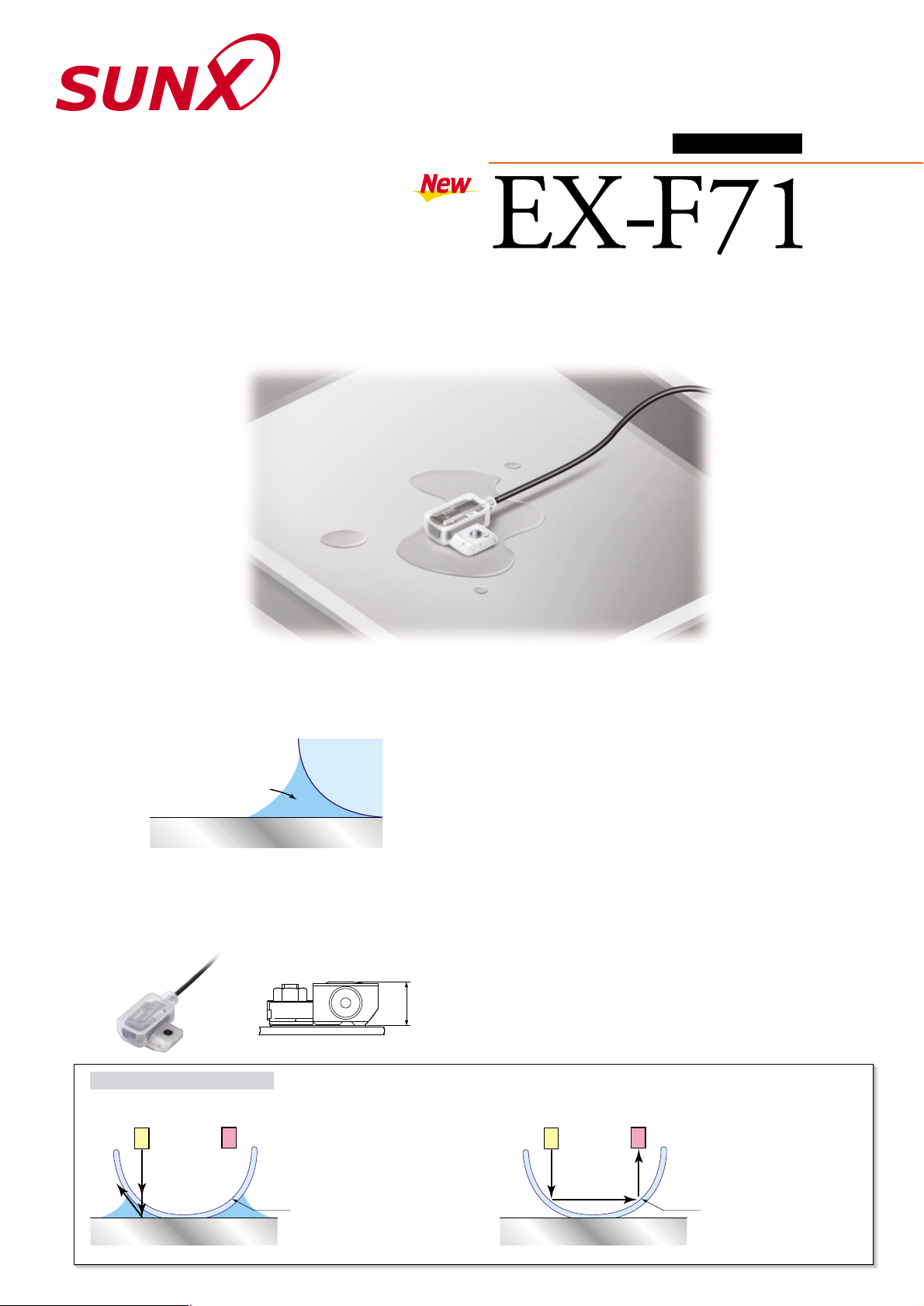
High-speed Detection
Even a Little Chemical Leak
LEAK SENSOR
Amplifier built-in
Reliable Detection
The unique effect of capillarity enables reliable detection of small leaks
and viscous liquids.
Capillarity effect
Liquid
Fiber head
Leakage pan
Compact, Space-saving
This slim (10mm) side-mounting sensor is especially good for use in
confined spaces.
10mm
approx.
New Type of Detection Method
● When a leak occurs, the beam form the beam-emitting part scatters through the leaked liquid and is not transmitted to the beam-receiving part.
Beam-emitting part
Beam-receiving part
Leaked
liquid
Leakage pan
Sensing
surface
When leakage occurs
The beam from the beamemitting part scatters
through the leaked liquid
and is not transmitted to
the beam-receiving part.
When there is no leakage
The beam from the beamemitting part reflects off of
the surface of the sensor
and is transmitted to the
beam-receiving part.
Beam-emitting part
Beam-receiving part
Sensing
surface
Leakage pan
Safe Design
● If the sensor is not mounted correctly, if the cable is cut or
disconnected, or if the sensor is not operating correctly, the output
is the same as when the beam is not received (LEAK).
● Design deals with human errors such as, forgetting to mount, etc.
Easy Operation Check
This sensor is equipped with a NORMAL indicator (green) which
lights up when mounting correctly, and a FAULT indicator (red) which
lights up when sensing the leaked liquid or when mounted incorrectly
(forgetting to mount exclusive mounting bracket). So, the operation
can be checked easily.
No Need for Sensitivity Adjustment
No need for sensitivity adjustment with adjuster, so initial mounting is
easy.
Easy Installation & Reset
● Bracket mounted with one screw, one-touch sensor mounting.
● No resetting or component replacement required after leak detection.
● The simple shape makes it easy to wipe off the leaked liquid.
Page 2
This product is not a safety sensor. Its use is not intended
or designed to protect life and prevent body injury or
property damage from dangerous parts of machinery. It is
a normal object detection sensor.
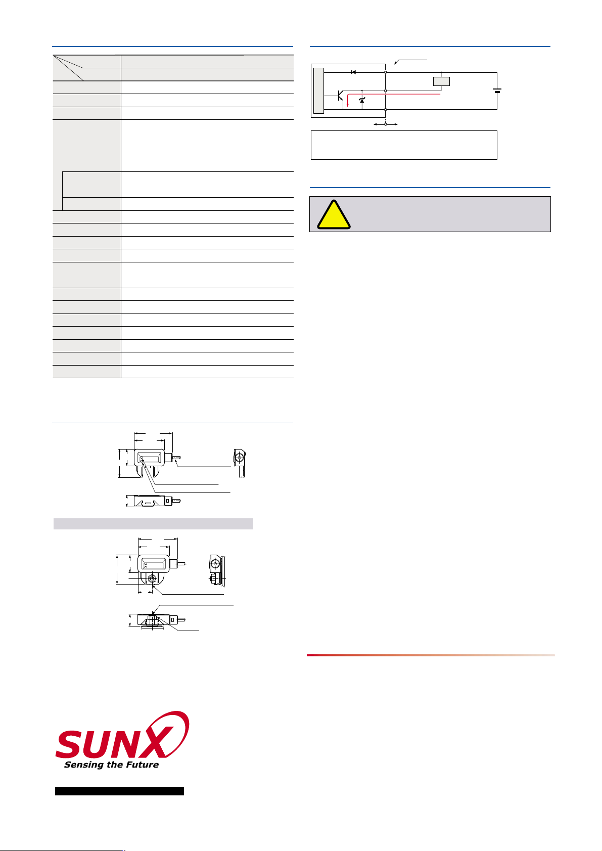
SPECIFICATIONS I/O CIRCUIT DIAGRAM
PRECAUTRIONS FOR PROPER USE
DIMENSIONS (Unit: mm)
!
Wiring
Mounting
Others
Assembly dementions with SUS mounting bracket
Designation
Model No.
Item
Sensing object
Supply voltage
Current consumption
Output
Response time
FAULT indicator
NORMAL indicator
Protection
Ambient temperature
Ambient illuminance
Emitting element
Material
Cable
Cable extension
Weight
Accessory
Water, Fluorinert (Note 1)
12 to 24V DC
10% Ripple P-P 10% or less
10mA or less
Incorporated
50ms or less
Red LED (In case liquid leaks or the sensor is mounted erroneously)
Green LED (In case the sensor is mounted normally)
IP67 (IEC)
10 to 60C (No dew condensation or icing allowed)
Storage: 20 to 70C (Note 2)
Incandescent light: 500
?
x at the light-receiving face
Infrared LED (non-modulated)
Enclosure: Polypropylene
0.1mm
2
3-core PVC cabytyre cable, 2m long
Extension up to total 50m is possible with 0.3mm
2
, or more, cable.
25g approx.
SUS mounting bracket
Amplifier built-in leak sensor
EX-F71
Notes: 1) Highly viscous liquid may not be detected stably.
2)
Liquid being detected should also be kept within the rated ambient temperature range.
Symbols ... D
Z
D
Tr
: Reverse supply polarity protection diode
: Surge absorption zener diode
: NPN output transistor
Users’ circuitInternal circuit
50mA max.
Tr
D
ZD
(Blue) 0V
12 to 24V DC
10%
(Brown) V
(Black) Output
Color code
Load
28.5
16
26.5
5.5
13
(Straight type)
SUS mounting bracket
M4 nut
11
35.9
"2.5 cable 2m long
26.5
16
35.9
28.5
FAULT indicator (Red)
NORMAL indicator (Green)
10.7
NPN open-collector transistor
• Maximum sink current: 50mA
•
Applied voltage: 30V DC or less (between output and 0V)
• Residual voltage: 1.0V or less (at 50mA sink current)
0.4V or less (at 16mA sink current)
In normal state: ON
When liquid leaks, or the sensor is mounted erroneously: OFF
Output operation
Short-circuit protection
Sensor circuit
• Make sure to carry out the wiring in the power supply off condition.
• Verify that the supply voltage variation is within the rating.
• Take care that if a voltage exceeding the rated range is applied, or if an AC
power supply is directly connected, the sensor may get burnt or damaged.
• If power is supplied from a commercial switching regulator, ensure
that the frame ground (F.G.) terminal of the power supply is connected to
an actual ground.
•
In case noise generating equipment (switching regulator, inverter motor,
etc.) is used in the vicinity of this product, connect the frame ground (F.G.)
terminal of the equipment to an actual ground.
•
Extension up to total 50m is possible with 0.3mm2, or more, cable. However,
in order to reduce noise, make the wiring as short as possible.
•
Do not run the wires together with high-voltage lines or power lines or
put them in the same raceway. This can cause malfunction due to induction.
• Ensure that an isolation transformer is utilized for the DC power supply. If
an autotransformer is utilized, the main amplifier or power supply may be
damaged.
• In case a surge is generated in the used power supply, connect a surge
absorber to the supply and absorb the surge.
•
If air bubbles are trapped within the sensing portion, take care that extra time
may be required to obtain stable sensing, or stable sensing may not be
achieved. Before use, thoroughly check the conditions under which the
sensor is used.
• For proper treatment after a liquid leak, ensure that all liquid is completely
wiped off from both the sensor's sensing surface and from SUS mounting
bracket. A soft cloth must be used to ensure that scratches or other
damage do not occur.
If the sensing surface or SUS mounting bracket is scratched, or if any
traces of liquid remain, then normal functionality will be impaired.
• Do not use during the initial transient time (30 sec. approx.) after the power
supply is switched on.
• Since the sensor is non-modulated type, take sufficient care against
extraneous light. Make sure that extraneous light is not directly incident on
the sensing surface.
• These sensors must not be used at locations containing high levels of
steam or dust, nor used within dangerous atmospheres, such as those
containing corrosive gases.
• Take care that the product does not come in direct contact with organic
solvents, such as, thinner, etc.
• If these sensors are used in an environment where static electricity is
generated, then the pan used to contain liquid leaks must be made of
metal and connected to a proper electrical ground.
No. LCE-EXF71-5 August, 2001
2431-1 Ushiyama-cho, Kasugai-shi, Aichi,
486-0901, Japan
Phone: +81-(0)568-33-7211
FAX: +81-(0)568-33-2631
SUNX Limited
Phone: +81-(0)568-33-7861
FAX: +81-(0)568-33-8591
Overseas Sales Dept.
Printed on 100% recycled paper PRINTED IN JAPAN
http://www.sunx.co.jp/
All information is subject to change without prior notice.
•
Be sure to use SUS mounting bracket when installing the sensor to avoid human
error. Reliable detection cannot be guaranteed when this mounting bracket is not
used.
•
Tightening torque of SUS mounting bracket should be 0.98Nm or
less.
M4 (length 10mm) stud bolt
 Loading...