

Panasonic EXC24CN, EXC24CB-CP User Manual
2 mode Noise Filters
Typ e:
EXC24CB/CP
EXC24CN
2 mode Noise Filters
■ Features
● Burst/radiation noise fi ltering for audio circuits
● The optimally magnetic-coupled ferrite beads allow for
the fi ltering of both common and normal mode noises
● The strong multi-layer structure provides high resistance
to refl ow soldering heat and a high mounting reliability
● Magnetic shield type
● High Impedance : 220 to 1 k액(EXC24CB type)
● Low Resistance Value : 0.4 액 max. (EXC24CP type)
● High Impedance : 600 액,
Low Resistance Value : 0.9 액 max. (EXC24CN type)
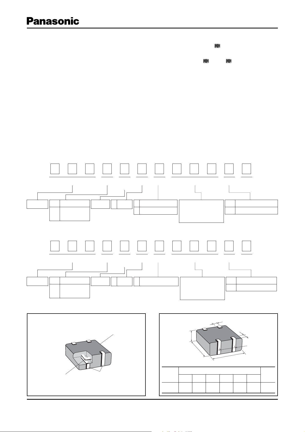
■ Explanation of Part Numbers
EXC24CB/CP Type
●
Noise Filter
1
E
Code
2
2
X
Product Code Type
Dimensions(mm)
1.25 ҂ 1.00 ҂ 0.50
(L) ҂ (W) ҂ (H)
3
C
4Terminals
4
2
Size Nominal Impedance Form Suffix
Number of
Terminals
Coupled
C
type
5
4
6
C
High Impedance Type
B
Low DCR Type
P
■ Recommended Applications
● Receiver lines, speaker lines, microphone lines and
headset of mobile phones.
● Audio signal lines of Portable audio equipment, PCs,
PDAs.
7
B
Characteristics
8
1
9
0
The first two digits are
significant figure of
impedance value, and the
third one denotes the
number of zeros following
10
2
11 12
U
Code
U
Packing
Embossed Carrier Taping
EXC24CN Type
●
Noise Filter
1
E
Code
2
2
X
Product Code Type
Dimensions(mm)
1.25 ҂ 1.00 ҂ 0.50
(L) ҂ (W) ҂ (H)
3
C
4Terminals
4
2
Size Nominal Impedance Form Suffix
Number of
Terminals
Coupled
C
type
5
4
6
C
High Impedance Type
N
and Low DCR Type
7
N
Characteristics
8
6
9
0
The first two digits are
significant figure of
impedance value, and the
third one denotes the
number of zeros following
10
1
11 12
X
Code
X
■ Construction ■ Dimensions in mm (not to scale)
F
Inner Conductor
Electrode
Ferrite
Type
(inches)
EXC24C
(0504)
C
A
B
Dimensions (mm)
ABCDE F
1.00±0.15 1.25±0.15 0.50±0.10 0.20±0.15 0.65±0.10 0.35±0.10
Packing
Pressed Carrier Taping
D
E
Mass
(Weight)
[mg/pc.]
3
Design and spec ifi cations are e ach subj ect to change w ithout notic e. Ask f actory for t he cur rent technical speci fi cations before purchase and/or use.
Should a sa fet y concern ar ise reg arding th is product, please be sure to c ontac t us immediately.
Feb. 2008
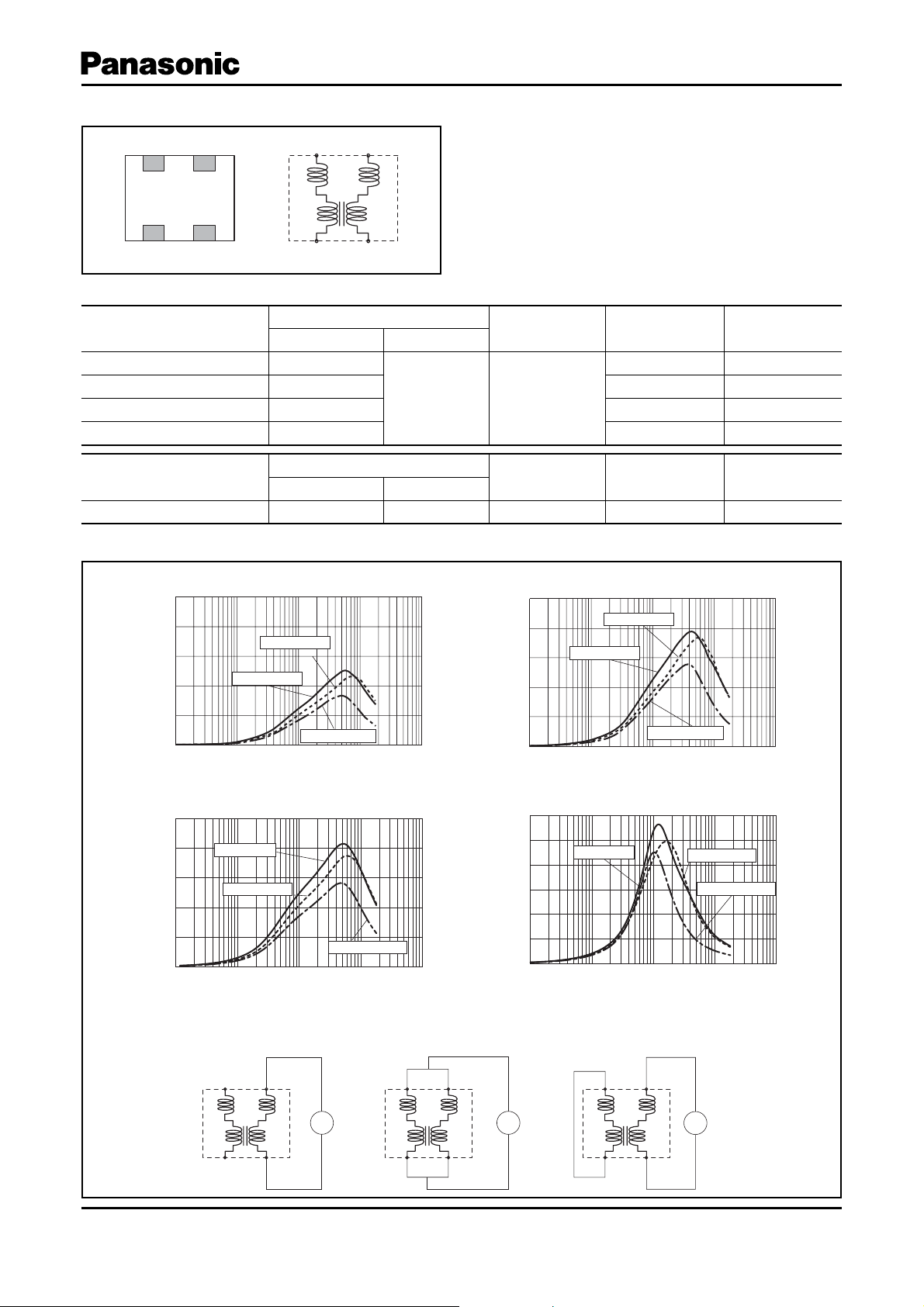
■ Circuit Confi guration (No Polarity)
2 mode Noise Filters
43
12
43
12
■ Ratings
Part Number
EXC24CP121U
EXC24CP221U
EXC24CB221U
EXC24CB102U
Part Number
EXC24CN601X
Impedance (Open mode)
(액) at 100 MHz Tolerance(%)
120
220 350 0.4
220 100 0.7
1000 50 1.5
Impedance (Common mode)
(액) at 100 MHz Tolerance(%)
600 ±25 5 200 0.9
■ Impedance Characteristics (Typical)
EXC24CP121U
●
500
400
300
200
Impedance(액)
100
0
EXC24CB221U
●
500
400
300
200
Impedance(액)
100
0
110100 1000 10000
Open mode
110100 1000 10000
Normal mode
Open mode
Common mode
Frequency(MHz)
Normal mode
Common mode
Frequency(MHz)
Rated Voltage
(V DC)
±25 5
Rated Voltage
(V DC)
EXC24CP221U
●
500
400
300
200
Impedance(액)
100
0
110100 1000 10000
EXC24CB102U
●
1200
1000
800
600
400
Impedance(액)
200
0
110100 1000 10000
Rated Current
(mA DC)
500 0.3
Rated Current
(mA DC)
Normal mode
Open mode
Common mode
Frequency(MHz)
Open mode
Frequency(MHz)
Normal mode
Common mode
DC Re sis tance
(액) max.
DC Re sis tance
(액) max.
Measurement Circuit
●
(A)Open Mode (B)Common Mode (C)Normal Mode
Z
Design and spec ifi cations are e ach subj ect to change w ithout notic e. Ask f actory for t he cur rent technical speci fi c ations before purchase and/or use.
Should a sa fet y concern ar ise reg arding th is product, please be sure to c ontac t us immediately.
Z
Z
Feb. 2008
 Loading...