

Panasonic EX-42 Installation Manual
Thank you very much for using SUNX products. Please read
this Instruction Manual carefully and thoroughly for the correct and optimum use of this product. Kindly keep this manual in a convenient place forquick reference.
INSTRUCTION MANUAL
Photoelectric Sensor
Fixed-focus Reflective Type
WARNING
EX-40 Series
1
SPECIFICATIONS
Type
Item
Sensing range
Supply voltage
Current consumption
Output
Timer function
Emitting element
Model No. (Note 1)
Output operation
Short-circuit protection
5 to 38mm (Conv. point: 20mm)
with white non-glossy paper
(5050mm)
NPN open-collector transistor
Maximum sink current: 100mA
Applied voltage: 30V DC or less (between output and 0V)
Notes: 1)2)The model No. with suffix '-C5' stands for the 5m cable length type.
(e.g.) As for the 5m cable length type of EX-42 'EX-42-C5'
The timer is always effective.
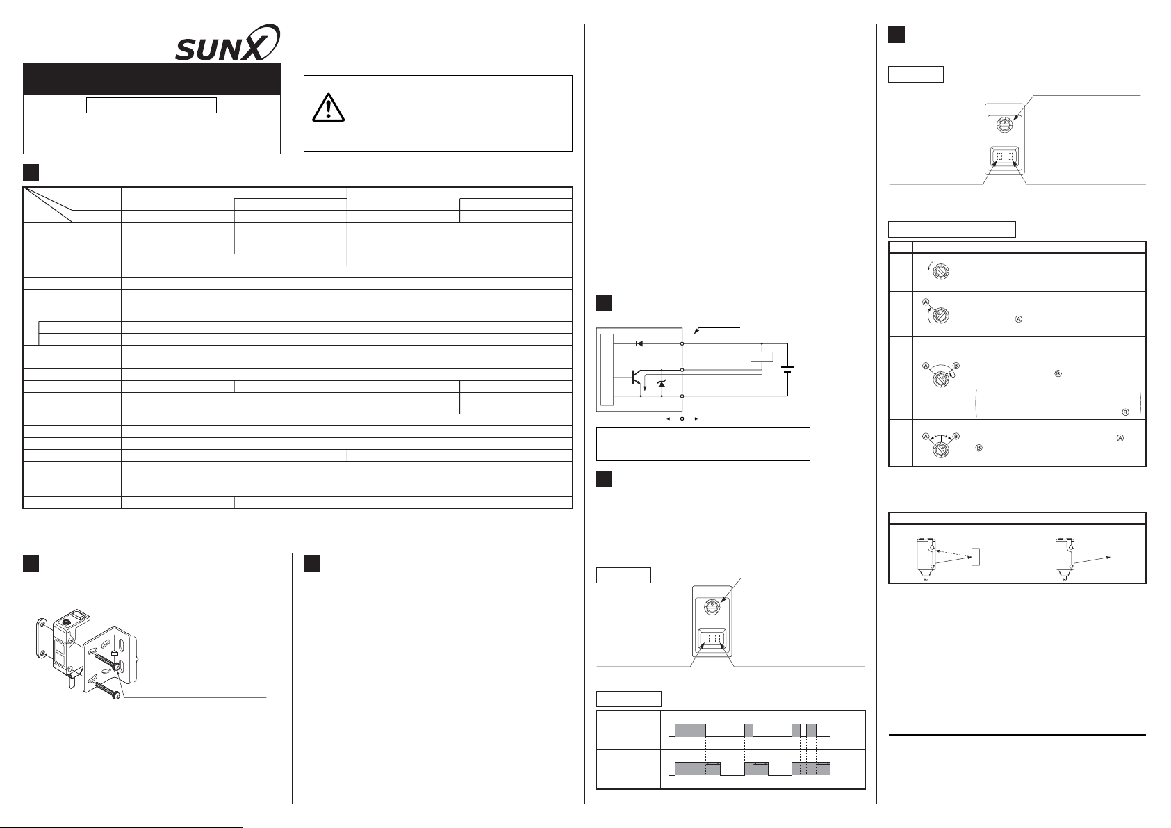
2
MOUNTING
٨ With the optional sensor mounting bracket, the
tightening torque should be 0.5N㨯morless.
Sensor mounting bracket
MS-EX40-1
(Optional)
M3 (length 16mm) screw with washers
Diffused beam type Spot-beam type
Green LED (lights up under stable light received condition or stable dark condition)Stability indicator
㧙㧙
-25 to +55 (No dew condensation or icing allowed), Storage: -30 to +70Ambient temperature
Infrared LED (modulated) Red LED (modulated)
㧙
Long sensing range With timer
10 to 70mm (Conv. point: 40mm)
with white non-glossy paper
(5050mm)
EX-44 EX-43 EX-43TEX-42
12 to 24V DCr10% Ripple P-P 10% or less
Red LED (lights up when the output is ON)Operation indicator
35 to 85% RH, Storage: 35 to 85% RHAmbienthumidity
0.2mm
35mA or less
Light-ON
Incorporated
0.5ms or lessResponse time
Continuously variable adjusterSensitivity adjuster
㧙
IP67 (IEC)Protection
PolyalylateMaterial
2
3-core cabtyre cable, 2m longCable
45g approx.Weight
3
CAUTIONS
EX-42 and EX-43T are not incorporated with a sen-
٨
sitivity adjuster. For these models, in case there is a
reflective object (e.g., a conveyor, etc.) in the background of the sensing object, since it may affect the
sensing, use by keeping enough distance from the
reflective object.
Make sure that the power supply is off while wiring.
٨
Take care that wrong wiring will damage the sensor.
٨
Verify that the supply voltage variation is within the
٨
rating.
If power is supplied from a commercial switching
٨
regulator, ensure that the frame ground (F.G.) terminal of the power supply is connected to an actual
ground.
In case noise generating equipment (switching reg-
٨
ulator, inverter motor, etc.) is used in the vicinity of
this product, connect the frame ground (F.G.) terminal of the equipment to an actual ground.
٨٨Never use this product as a sensing de-
vice for personnel protection.
In case of using sensing devices for personnel protection, use products which meet laws and standards, such as OSHA, ANSI or IEC etc., for personnel protection applicable in each region or country.
20 to 35mm (Conv. point: 30mm)
with white non-glossy paper (5050mm)
10% or less of operation distance15% or less of operation distanceHysteresis
Residual voltage: 1.5V or less (at 100mA sink current)
Adjusting screwdriver: 1 pc.Accessory
0.4V or less (at 16mA sink current)
Variable OFF-delay timer (0.1
to 1 sec. approx.) (Note 2)
٨
Do not run the wires together with high-voltage lines or
power lines or put them in the same raceway. This can
cause malfunction due to induction.
٨
Extension up to total 100m, is possible with 0.3mm
or more, cable. However, in order to reduce noise,
make the wiring as short as possible.
٨
Do not use during the initial transient time (50ms) after
the power supply is switched on.
٨
Take care that the sensor is not directly exposed to fluorescent
lamp from a rapid-starter lamp, a high frequency lighting device or sunlight etc., as it may affect the sensing performance.
٨
Avoid dust, dirt, and steam. Do not use it in places
having excessive vapor, dust, etc., or where it may
come in direct contact with corrosive gas.
٨
Take care that the sensor does not come in direct contact with water, oil, grease, organic solvents, such as,
thinner etc., or strong acid, and alkaline.
٨
Make sure that stress by forcible bend or pulling is not
applied directly to the sensor cable joint.
٨
Since the cable end is not waterproof, do not use the
sensor in the application where water may seep in
from the cable end.
4
I/O CIRCUIT DIAGRAMS
D
Tr
Sensor circuit
Internal circuit Users' circuit
Symbols...D
5
:
D
Z
:
Tr
:
TIMER FUNCTION (only for EX-43T)
Color code
(Brown) +V
oad
L
(Black) Output
D
(Blue) 0V
100mA max.
Z
Reverse supply polarity protection diode
Surge absorption zener diode
NPN output transistor
+
-
12 to 24V DC
r10%
٨ EX-43T has an approx. 0.1 to 1 sec. variable OFF-de-
lay timer. Since the output is extended for a fixed time
interval, it is useful when the response time of the connected device is slow or when the signal width is small
due to sensing of small objects.
(The timer is always effective.)
Top face
Operation indicator (Red)
Lights up when the output
is ON.
Timer adjuster
OFF-delay time becomes longer
if it is turned clockwise.
Stability indicator (Green)
Lights up under stable light received
condition or stable dark condition.
Time chart
Sensing
condition
Output
operation
TT T
Timer period: T = 0.1 to 1 sec. approx.
Light
Dark
ON
OFF
6
SENSITIVITY ADJUSTMENT
2
,
(only for EX-43, EX-44)
Top face
Sensitivity adjuster
The sensing range increases
when turned clockwise.
Operation indicator (Red)
Lights up when the output
is ON.
Stability indicator (Green)
Lights up under stable light received condition or stable dark
condition.
Sensitivity adjustment
Step
Sensitivity adjuster
Turn the sensitivity adjuster fully counter-
Ԙ
ԙ
Ԛ
Optimum position
ԛ
clockwise to the minimum sensitivity posi-
MAX.MIN.
tion, MIN.
In the light received condition, turn the sensi-
tivity adjuster slowly clockwise and confirm
the point where the sensor enters the
MAX.MIN.
'Light' state operation.
In the dark condition, turn the sensitivity ad-
juster further clockwise until the sensor enters
the 'Light' state operation and then bring it
back to confirm point where the sensor just
returns to the 'Dark' state operation.
MAX.MIN.
If the sensor does not enter the 'Light' state operation even when the sensitivity adjuster is
turned fully clockwise, the position is point .
The position at the middle of points and
is the optimum sensing position.
MAX.MIN.
Note: Use the accessory adjusting screwdriver to turn the
adjuster slowly. Turning with excessive strength will
cause damage to the adjuster.
'Light' condition 'Dark' condition
Sensor
Sensing object
SUNX Limited
Head Office
2431-1 Ushiyama-cho, Kasugai-shi, Aichi, 486-0901, Japan
Phone: +81-(0)568-33-7211 FAX: +81-(0)568-33-2631
Overseas Sales Dept.
Phone: +81-(0)568-33-7861 FAX: +81-(0)568-33-8591
Description
Sensor
http://www.sunx.co.jp/
PRINTED IN CHINA
 Loading...