

Panasonic EURO7 TX36PG50 Schematic
SPECIFICATIONS
Power Source: 220-240V a.c., 50Hz
Power Consumption: 181W
Stand-by Power
Consumption: 2.8W
Aerial Impedance: 75Ω unbalanced, Coaxial Type
Receiving System: PAL I, PAL-525/60
M.NTSC
NTSC (AV only)
Receiving Channels: UHF E21-E69
Intermediate Frequency:
Video/Audio
Video 39.5MHz
Audio 33.5MHz
32.95MHz (NICAM)
Colour 35.07MHz
Terminals:
AV1 IN Video (21 pin) 1V p-p 75Ω
Audio (21 pin) 500mV rms 10kΩ
RGB (21 pin)
AV1 OUT Video (21 pin) 1V p-p 75Ω
Audio (21 pin) 500mV rms 1kΩ
ORDER No. SM-01001
Colour Television
TX-36PG50
EURO-7 Chassis
Audio (21 pin) 500mV rms 10kΩ
S-Video IN Y: 1V p-p 75Ω
(21-pin) C: 0.3V p-p 75Ω
RGB (21 pin)
AV4 OUT Video (21 pin) 1V p-p 75Ω
Audio (21 pin) 500mV rms 1kΩ
High Voltage: 32kV ± 1kV
Picture Tube: W86LPX955X07 86cm
Audio Output: Front Left/Right 2 x 20W
(Music Power) Subwoofer 23W
External Centre 19W
External Surround 2 x 19W
8Ω Impedance
Digital Audio Input Coaxial / Optical
Dolby Surround Out 6 x Dolby Surround Out RCA
(Rear)
Headphones: 8Ω Impedance
3.5mm
Accessories
supplied : Remote Control
2 x R6 (UM3) Batteries
TS-36PG50 Cabinet / Speaker pack
AV2 IN Video (21 pin) 1V p-p 75Ω
Audio (21 pin) 500mV rms 10kΩ
S-Video IN Y: 1V p-p 75Ω
(21-pin) C: 0.3V p-p 75Ω
AV2 OUT Video (21 pin) 1V p-p 75Ω
Audio (21 pin) 500mV rms 1kΩ
Selectable output (21 pin)
AV3 IN S-Video IN Y: 1V p-p 75Ω
(4-pin) C: 0.3V p-p 75Ω
Audio (RCAx2) 500mV rms 10kΩ
Video (RCAx1) 1V p-p 75Ω
AV4 IN Video (21 pin) 1V p-p 75Ω
Dimensions:
Height: 637mm
Width: 874mm
Depth: 585mm
Net weight: 85kg
Specifications are subject to change without notice.
Weights and dimensions shown are approximate.
NOTE: This Service Manual should be used in conjunction with
the EURO-7 Technical guide.
Panasonic CS ( U.K. ) Ltd.
WILLOUGHBY ROAD,
BRACKNELL,
BERKS.,
RG12 8FT.
CONTENTS
SAFETY PRECAUTIONS..........................................................................................................................................................2
SERVICE HINTS.......................................................................................................................................................................3
SERVICE POSITION.................................................................................................................................................................4
ADJUSTMENT PROCEDURE AND FACTORY SETTINGS.....................................................................................................5
WAVEFORM PATTERN TABLE...............................................................................................................................................6
ALIGNMENT SETTINGS...........................................................................................................................................................7
BLOCK DIAGRAMS..................................................................................................................................................................8
PARTS LOCATION.................................................................................................................................................................13
REPLACEMENT PARTS LIST................................................................................................................................................14
SCHEMATIC DIAGRAMS.......................................................................................................................................................30
CONDUCTOR VIEWS.............................................................................................................................................................37
SAFETY PRECAUTIONS
GENERAL GUIDE LINES
1. It is advisable to insert an isolation transformer in the
a.c. supply before servicing a hot chassis.
2. When servicing, observe the original lead dress in the
high voltage circuits. If a short circuit is found, replace
all parts that have been overheated or damaged by
the short circuit.
3. After servicing, see that all the protective devices
such as insulation barriers, insulation papers, shields
and isolation R-C combinations are correctly
installed.
4. When the receiver is not being used for a long period
of time, unplug the power cord from the a.c. outlet.
5. Potentials as high as 33kV are present when this
receiver is in operation. Operation of the receiver
without the rear cover involves the danger of a shock
hazard from the receiver power supply. Servicing
should not be attempted by anyone who is not
familiar with the precautions necessary when working
on high voltage equipment. Always discharge the
anode of the tube.
6. After servicing make the following leakage current
checks to prevent the customer from being exposed
to shock hazard.
LEAKAGE CURRENT COLD CHECK
1. Unplug the a.c. cord and connect a jumper between
the two prongs of the plug.
2. Turn on the receiver’s power switch.
3. Measure the resistance value with an ohmmeter,
between the jumpered a.c. plug and each exposed
metallic cabinet part on the receiver, such as screw
heads, aerials, connectors, control shafts etc. When
the exposed metallic part has a return path to the
chassis, the reading should be between 4M ohm and
20M ohm. When the exposed metal does not have a
return path to the chassis, the reading must be
infinite.
LEAKAGE CURRENT HOT CHECK
1. Plug the a.c. cord directly into the a.c. outlet. Do not
use an isolation transformer for this check.
2. Connect a 2kΩ 10W resistor in series with an
exposed metallic part on the receiver and an earth,
such as a water pipe.
3. Use an a.c. voltmeter with high impedance to
measure the potential across the resistor.
4. Check each exposed metallic part and check the
voltage at each point.
5. Reverse the a.c. plug at the outlet and repeat each of
the above measurements.
6. The potential at any point should not exceed
1.4V rms. In case a measurement is outside the limits
specified, there is a possibility of a shock hazard, and
the receiver should be repaired and rechecked before
it is returned to the customer.
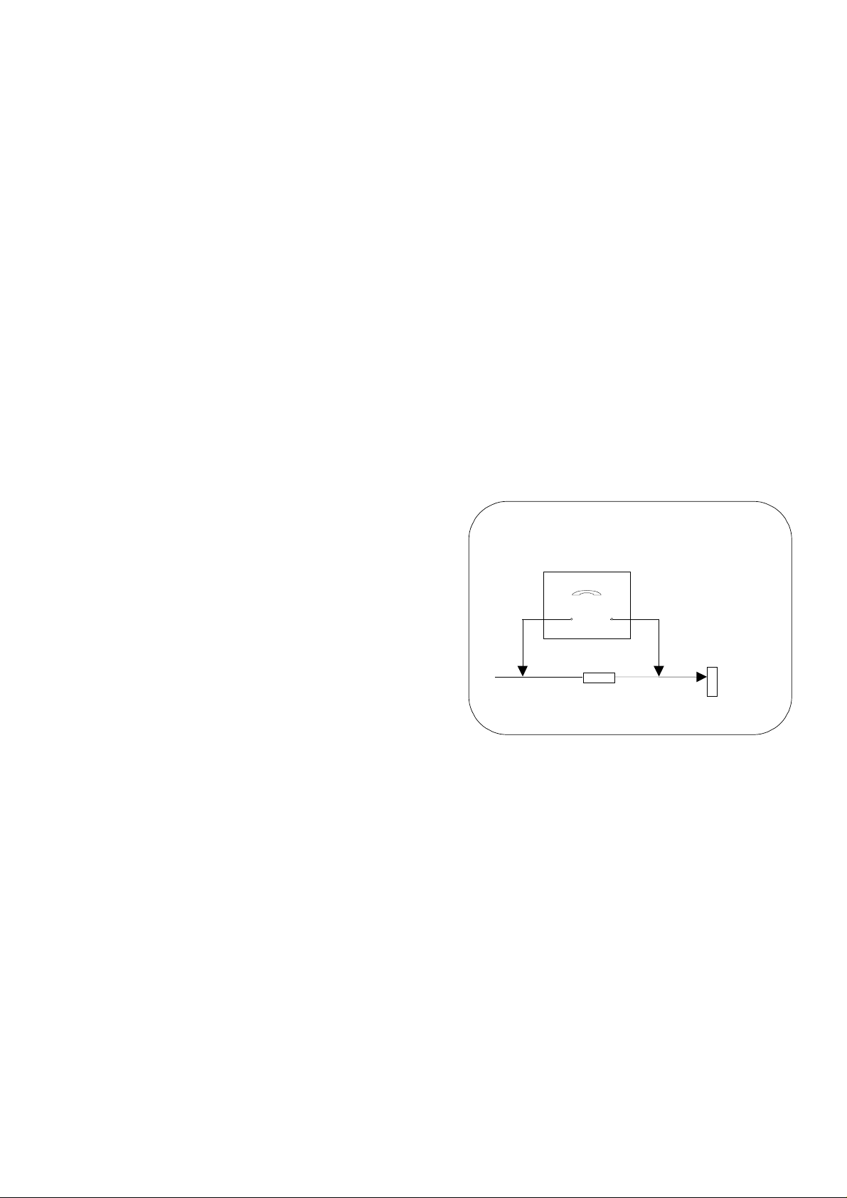
HOT CHECK CIRCUIT
a.c. VOLTMETER
2kΩ 10 Watts
TO INSTRUMENT’S EXPOSED
METALLIC PARTS
Fig. 1.
X-RADIATION WARNING
1. The potential sources of X-Radiation in TV sets are
the high voltage section and the picture tube.
2. When using a picture tube test jig for service, ensure
that the jig is capable of handling 33kV without
causing X-Radiation.
NOTE: It is important to use an accurate periodically
calibrated high voltage meter.
1. Set the brightness to minimum.
2. Measure the high voltage. The meter should indicate.
32kV ± 1kV.
If the meter indication is out of tolerance, immediate
service and correction is required to prevent the
possibility of premature component failure.
3. To prevent any X-Radiation possibility, it is essential
to use the specified tube.
WATER PIPE
(
EARTH)
2
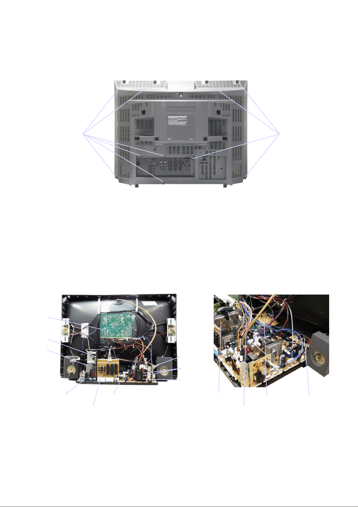
SERVICE HINTS
Focus
Screen
How to remove the rear cover
1. Remove the 10 screws as shown in Fig.2.
SCREWS
LOCATION OF CONTROLS
SCREWS
Fig.2.
L-Board
Z-Board
DP-Board
A-Board
H-Board
D-Board
DF-Board
Fig.3.
3
DG-Board
U-Board
G-Board
K-Board
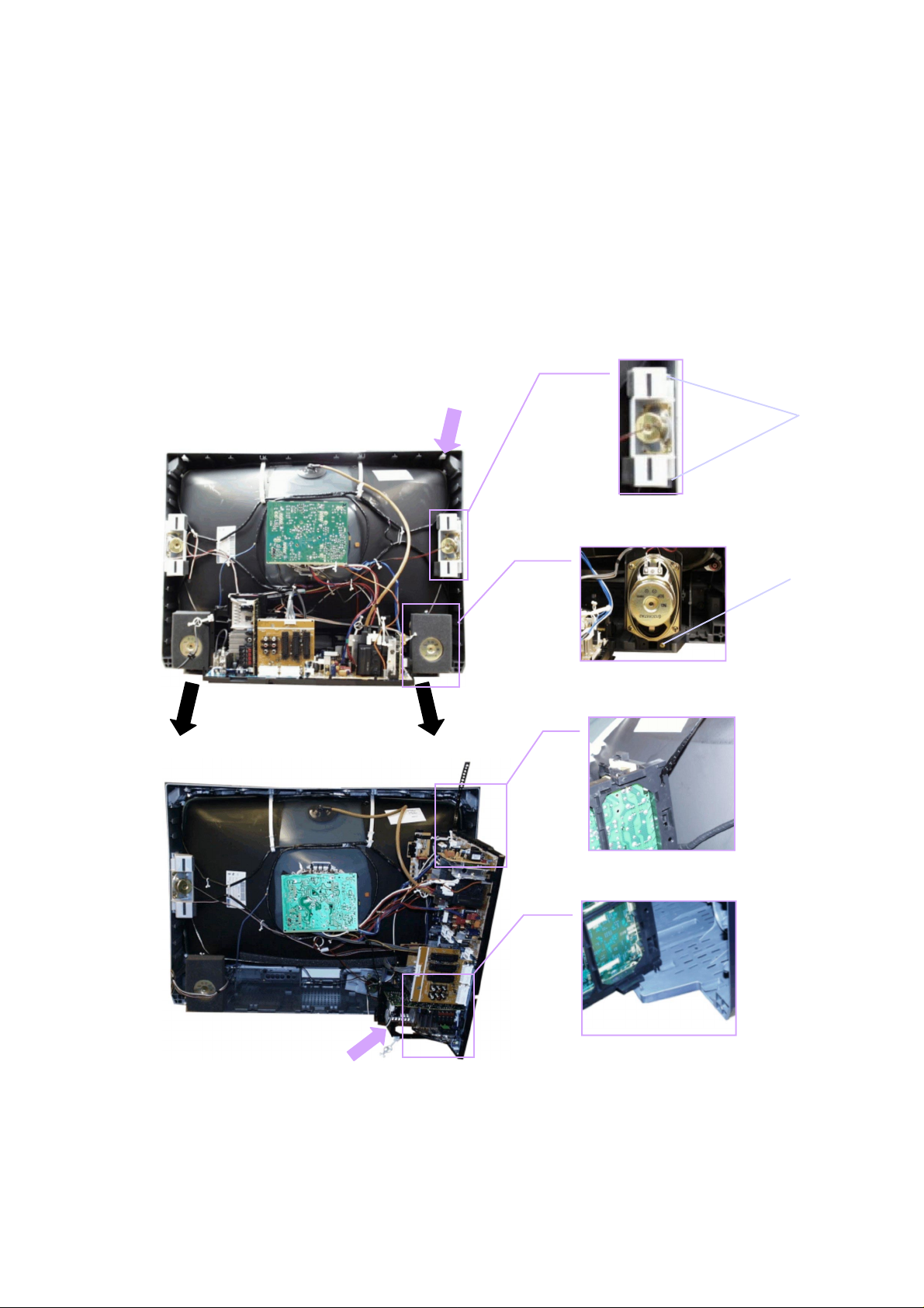
HOW TO MOVE THE CHASSIS INTO SERVICE POSITION
(C)
(D)
(A)
(B)
1. Remove the 3 screws (B) and (C) shown in Fig.5. / Fig.6., and remove the 2 speakers from the cabinet.
2. Affix the support strap supplied in the service pack (TZS1EK002) using a back cover screw, into the top right-hand
cabinet rib (A) shown in Fig.4.
3. Hold and lift the rear of the chassis and gently pull toward you, as shown in Fig.4.
4. Release the respective wiring clips and rotate the chassis vertically through 90°, anti-clockwise.
5. Locate the base of the chassis frame into location (D), shown in Fig.7. / Fig.9.
6. Clip the chassis frame onto the support strap, shown in Fig.7. / Fig.8.
7. After servicing replace the speakers, and ensure all wiring is returned to it’s original position before returning the receiver
to the customer.
Fig.5.
Fig.4.
Fig.7.
Fig.6.
Fig.8.
Fig.9.
4
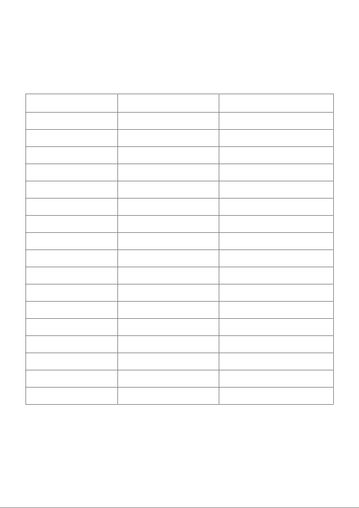
ADJUSTMENT PROCEDURE
Item / Preparation Adjusment/Confirmation
+B SET-UP
4. Receive a Window pattern.
5. Set the controls :Brightness Minimum
Contrast Minimum
Volume Minimum
CUT OFF
1. Receive a Window pattern.
2. Degauss the tube externally.
3. Set the TV into Service Mode 1.
4. Select Sub brightness mode.
Confirm the following voltages.
A - Board
A1 Pin2 7.5 ± 0.5V IC1252 Pin2 2.5 ± 0.25V
A1 Pin12 -20 ± 0.5V IC1251 Pin3 3.3 +0.3 / -0.2V
A1 Pin16 20 ± 0.5V IC3302 Pin3 12 ± 0.6V
A2 Pin15 30 ± 0.5V IC2707 Pin3 8 ± 0.4V
A2 Pin6 15 ± 0.5V L2707 (IC2708) 9 ± 0.4V
A3 Pin4 15 ± 0.5V L2704 (IC2706) 5 ± 0.2V
A3 Pin2 -15 ± 0.5V L2716 (IC2705) 3.3 ± 0.2V
D – Board
TPD8-GND 7.5 ±0.5V
TPD9-TPD11 38.5 ± 2V
TPD10-GND 15.5 ± 1V
TPD13-GND 14.5 ± 1V
TPD15-GND 144.8 ± 1V
TPD32-GND 209 ± 10V
C864-GND -15.5 ± 1V
D2 Pin15-GND 31 ± 1V
To adjust Cutoff connect an oscilloscope to the Blue cathode. Adjust "Cutoff"
value using the "Yellow" and "Blue" buttons until the black level is 170V ± 5V,
press "STR" to store the value. Remove the oscilloscope.
Select Highlight/Lowlight mode press "5" to collapse the screen and adjust the
screen “VR” until the display is just visible, press "5" to return to service mode.
Using the "Yellow" and "Blue" buttons adjust until optimum picture white
balance is achieved, press "STR " to store the value. Select Sub Brightness
mode and adjust until optimum picture brightness is achieved.
L2717 (IC2709) 3.3 ± 0.2V
FACTORY SETTINGS
To return customer settings to factory settings and clear owner ID of all information input by the customer, enter Self-Check
mode. Press the down (-/v) button on the customer controls at the front of the TV set, at the same time pressing the STATUS
button on the remote control. To exit Self Check, switch off the TV set at the power button.
NOTE: Self Check should only be used when refurbishing the TV set and not during normal repair work.
MEM : O.K.
GC1 : O.K.
GC2 : O.K.
VDU : O.K.
CIP : O.K.
RGB : O.K.
AVSW : O.K.
Tun1 : O.K.
Tun2 : O.K.
DAC1 : O.K.
MSP : O.K.
DOLBY : O.K.
CODEC : O.K.
DAC2 : O.K.
DAC3 : O.K.
Sum : ****
OPTION 1 : 01
OPTION 2 : 00
OPTION 3 : 13
OPTION 4 : 10
OPTION 5 : 00
OPTION 6 : 50
OPTION 7 : 80
OPTION 8 : 41
OPTION 9 : 83
OPTION 10 : 80
OPTION 11 : 19
OPTION 12 : 08
OPTION 13 : FA
Check : BA
Factory use only
If the CCU ports have been checked and found to be incorrect or not located then " - - " will appear in place of "O.K.".
5
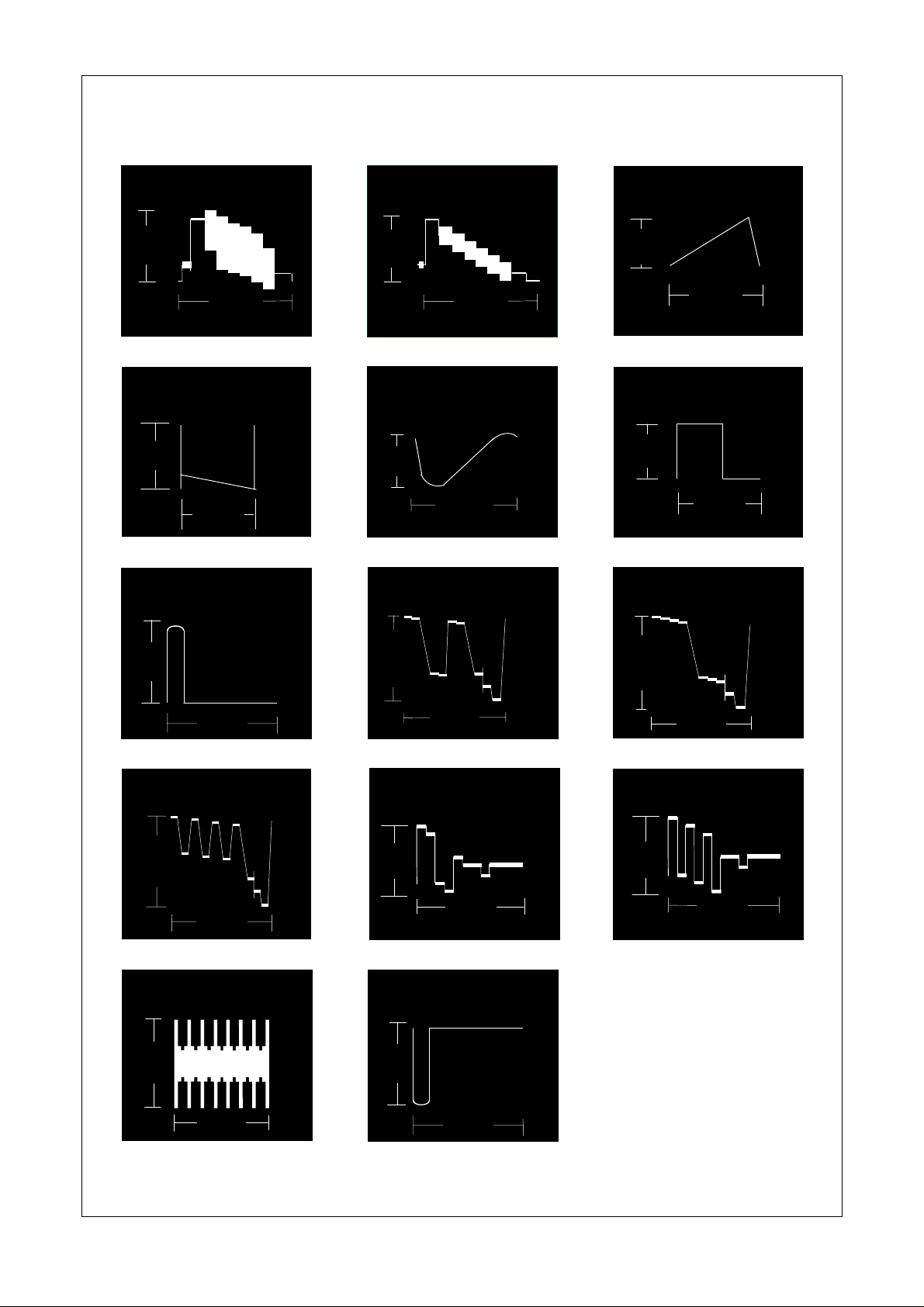
WAVEFORM PATTERN TABLE
Note: All waveforms have been taken using a standard colour bar pattern.
Video Out
IC3001 Pin 56
2.2V
Vert Out
IC451 Pin 3
88V
HFLB
A3 Pin 11
10mS
64µS
Luminance In
IC1315 Pin 37
0.9V
VFLB
IC451 Pin 6
1V
R - Out
IC1315 Pin 23
20mS
32µS
Vert Drive
A44 Pin 24
0.9V
10mS
H - Drive
A3 Pin 10
4V
32µS
G - Out
IC1315 Pin 21
4V
B - Out
IC1315 Pin 19
4V
SVM Out
A44 Pin 43
1V
32µS
32µS
4V
R - Y
IC1315 Pin 38
0.8V
E/W Out
IC501 Pin 1
8V
32µS
32µS
4V
32µS
B - Y
IC1315 Pin 39
0.8V
32µS
32µS
32µS
6
ALIGNMENT SETTINGS
(The figures below are nominal and used for representative purposes only.)
1. Set the Bass to maximum position, set the Treble to minimum position, press the down button (- / v) on the customer
controls at the front of the TV and at the same time press the INDEX button on the remote control, this will place the TV
into the Service Mode.
2. Press the RED / GREEN buttons to step up / down through the functions.
3. Press the YELLOW / BLUE buttons to alter the function values.
4. Press the STR button after each adjustment has been made to store the required values.
5. To exit the Service Mode, press the "N" button.
Alignment Function Settings / Special features
Horizontal Position
Vertical Position
Horizontal Amplitude
Vertical Amplitude
Parabola
Trapezoid
Horizontal Parallel
Vertical Linearity
Top Corner
Bottom Corner
Vertical Symmetry Correction
H – Pos
97
V – Pos
111
H – Amp
86
V – Amp
134
Parabola
26
Trapezoid
124
H – Parallel
13
V – Linear
34
Top – Corner
20
Bottom – Corner
20
V – S – Correct
9
Optimum setting.
Optimum setting.
Optimum setting.
Optimum setting.
Optimum setting.
Optimum setting.
Optimum setting.
Optimum setting.
Optimum setting.
Optimum setting.
Optimum setting.
Center Correction
DAF - Phase
Highlight
Lowlight
Sub-Brightness
Video Gain 2
Splitter Gain (Tuner)
C – Correct
10
DAF – Phase
205
High 0144 0126 0128
Low 0331 0340 0384
Sub-Brightness
144
Video Gain 2
157
SPL. Gain
0
Optimum setting.
Optimum setting.
Optimum setting.
Optimum setting.
Optimum setting.
Optimum setting.
7
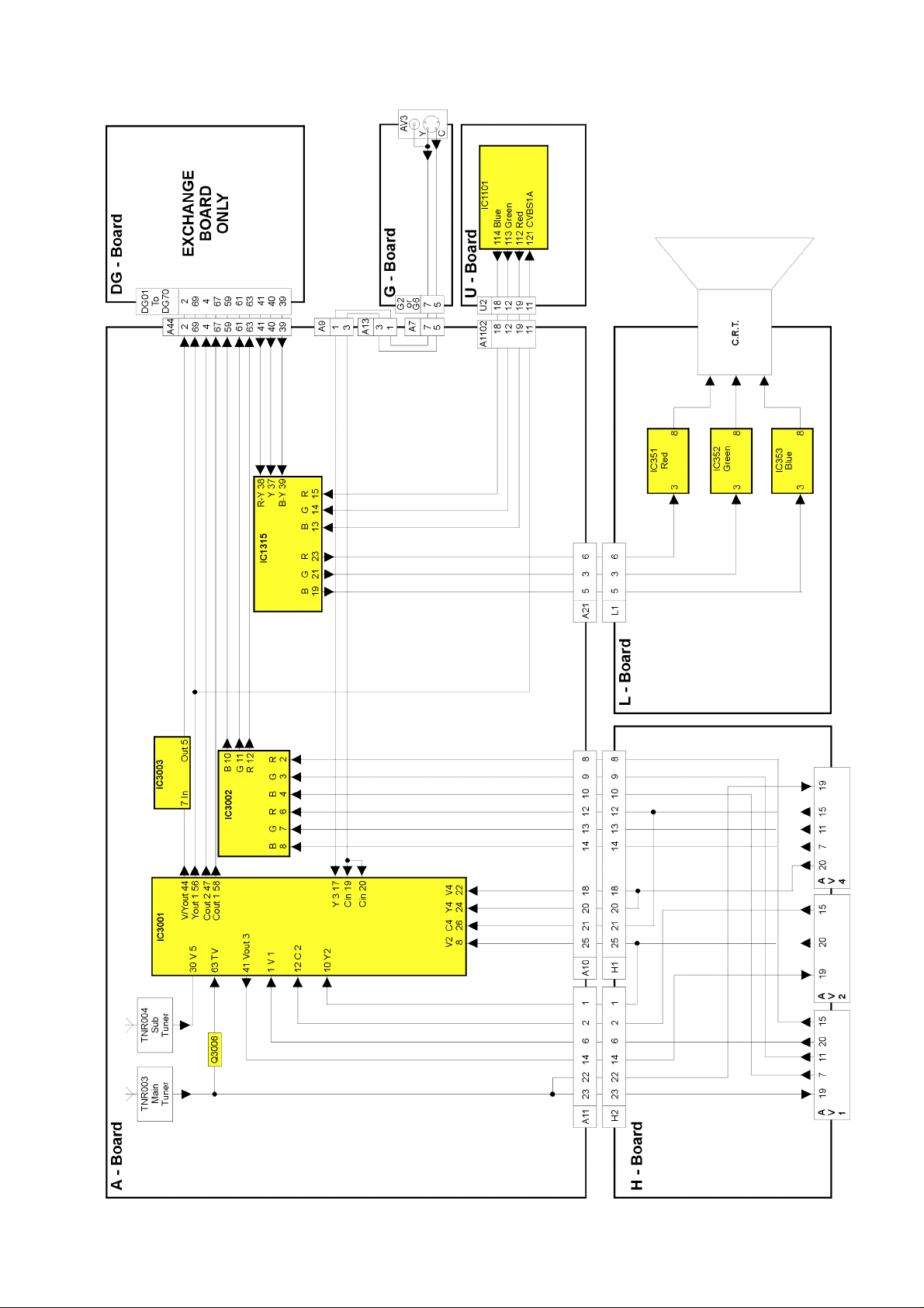
VIDEO BLOCK DIAGRAM
8
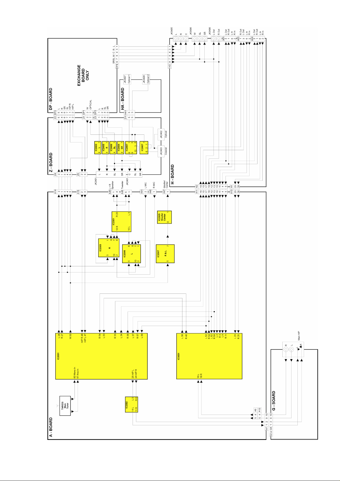
AUDIO BLOCK DIAGRAM
9
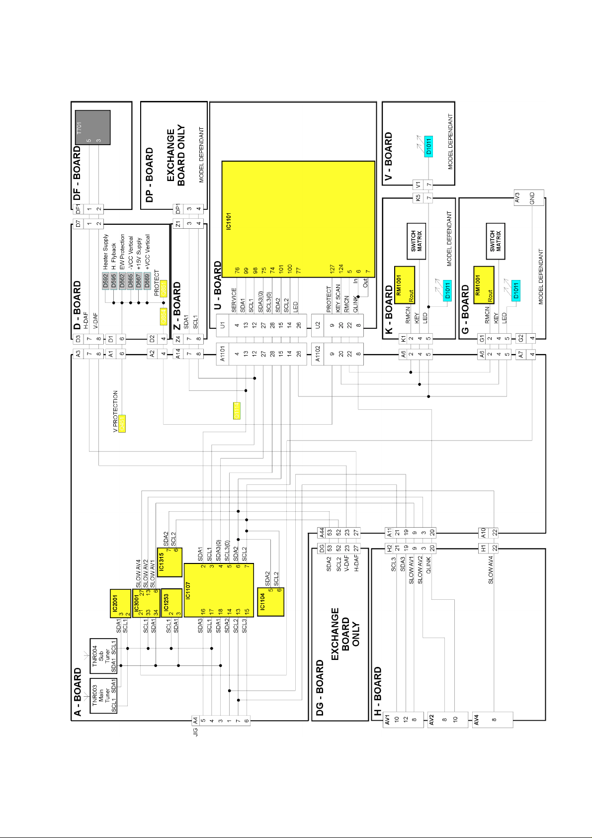
CONTROL BLOCK DIAGRAM
10
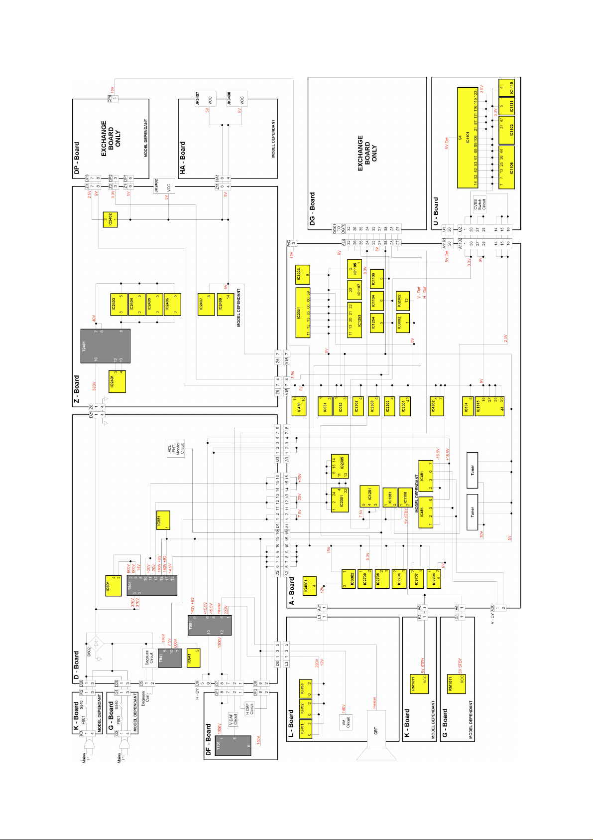
POWER SUPPLY BLOCK DIAGRAM
11
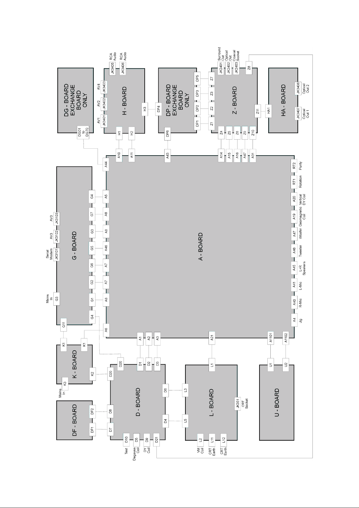
WIRING BLOCK DIAGRAM
12
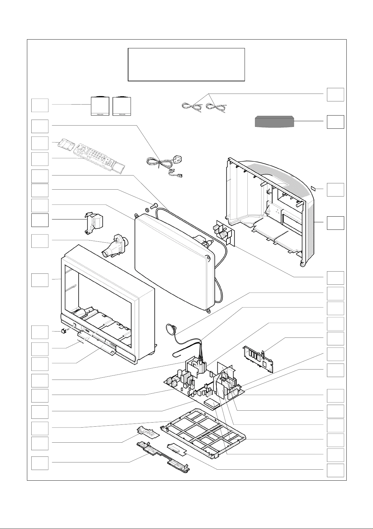
PARTS LOCATION
NOTE:
The numbers on the exploded view below
refer to the mechanical section of the
Replacement Parts List.
28
2
31
33
7
13
10
34
4
1
30
3
27
12
17
35
9
8
29
21
26
25
15
20
14
32
36
11
5
6
24
16
18
22
23
19
13
 Loading...