

Page 1
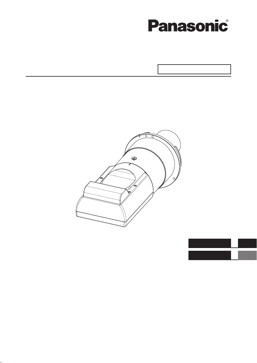
Operating Instructions
Fixed-focus Lens
Model No.
Commercial Use
ET-D75LE95
ENGLISH
FRANÇAIS
Thank you for purchasing this Panasonic product.
To ensure correct use of this lens, please read the operating instructions supplied with the lens and the
■
projector carefully.
Before using this product, be sure to read “Read this rst!” (
■
Please save this manual for future use.
■
Page 3).
DPQX1086ZA
Page 2

█ Contents
Read this rst! ......................................................................................3
Before Use.............................................................................................4
Attaching the Lens / Detaching the Lens ...........................................4
Before replacing the projection lens ........................................................ 4
Attaching the Lens...................................................................................5
Detaching the Lens .................................................................................6
Projection relationships.......................................................................7
Lens position setup and focus adjustment .......................................9
Lens position setup .................................................................................9
Focus Adjustment Function ................................................................... 11
Adjustment range by the lens position shift (optical shift) ............12
Specications .....................................................................................14
Dimensions .........................................................................................14
Dimensional relationship ...................................................... Appendix
2-ENGLISH
Page 3

Read this rst!
Always follow these precautions
WARNING:
Before replacing the projection lens, be sure to turn off the power and
disconnect the power plug from the wall outlet.
zUnexpected projection of light may cause injury to eyes.
zReplacing without removing the power plug may result in electrical shock.
Do not place objects near the light projecting surface.
zThis surface produces intense light. Failure to heed this warning could result in re
or burn injuries.
CAUTION:
Do not use the lens with the protective lm and lens cover left on.
zIf left on, the heat generated during projection could melt them resulting in projector
deformation and damage, and personnel attempting to remove them could suffer
burn injuries.
Do not open the desiccant bag. Do not eat the contents.
Inadvertently ingesting desiccant could be harmful.
zIf the desiccant gets into your eyes or mouth, immediately rinse with plenty of water
and seek medical attention.
zKeep desiccant out of the reach of children.
Note
zThis product cannot be used if an optional frame (ET-PFD510 / ET-PFD310) is attached and used with the projector.
Information for users in the European Union
Importer’s name and address within the European Union
Panasonic Marketing Europe GmbH
Panasonic Testing Centre
Winsbergring 15, 22525 Hamburg, Germany
ENGLISH-3
Page 4

Before Use
Supported projectors
PT-RZ31K / PT-RS30K / PT-RQ13K / PT-RZ12K / PT-RS11K / PT-DZ21K2 / PT-DS20K2 / PT-DW17K2 /
PT-DZ16K2 / PT-DZ13K / PT-DS12K / PT-DW11K / PT-DZ10K
Note
zModels other than the above may also be supported. Refer to the operating instructions of the projector you are using.
zIn this document, the alphabet letters at the end of the projector part numbers are omitted.
Supplied Accessories
Make sure that the following has been provided. Numbers enclosed in < > show the number of accessories.
Lens cover <1>
(The product is delivered with a lens cover attached.)
Attaching the Lens / Detaching the Lens
Before replacing the projection lens
Return the projection lens to the home position before replacing or removing it.
For details on how to return the lens to the home position, refer to the operating instructions of the projector.
Attention
zMake sure that the projector power supply is switched off before attaching or detaching the projection lens.
zAfter removing the projection lens, store it safely away from vibration or impacts.
zBefore attaching the xed-focus lens, remove the protective lm from the light projecting surface and the lens
cover from the lens.
Protective lm
Lens cover
Lens surface
zBe sure not to touch the light projecting surface or the surface of the lens. Any ngerprints or smudges on
these surfaces will be magnied and lower the quality of the image displayed on the screen.
zThe light projecting surface and lens are made of glass. The lens could be damaged if brought into contact
with or rubbed against hard objects. Handle the lens carefully.
zUse a clean, soft and dry cloth to wipe away any dirt or dust that has adhered to the light projecting surface or lens.
Do not use uffy cloths containing oil, water or dust for cleaning.
zWhen the xed-focus lens is removed from the projector, place it with the light projecting surface facing
upwards.
Light projecting surface
4-ENGLISH
Page 5

Attaching the Lens / Detaching the Lens (continued)
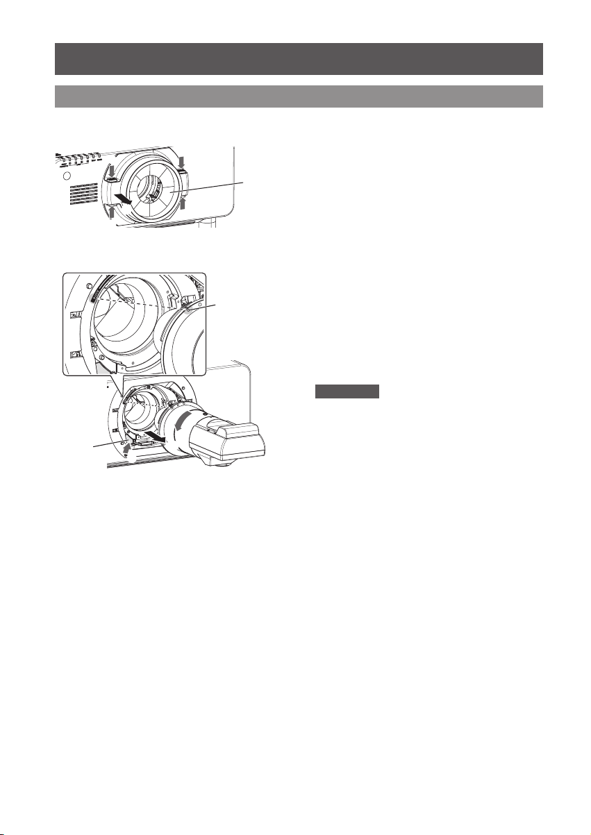
Attaching the Lens
The illustration for this procedure uses PT-DZ21K2
as an example.
1)
(i)
(ii)
(i)
(i)
Projection
lens cover
(i)
Orange color
(ii)
(i)
Remove the projection lens cover.*
2) Align the mark on the projection
lens (orange color) with the mark
on the projector (O on the left
side of the LOCK) and insert; then
rotate in a clockwise direction
until it makes a "click" sound.
1
3) Secure the projection lens with
the lens drop prevention screw
Lens drop
prevention
screw
included with the projector.
zSecure it in the screw hole (location shown in
the gure to the left) on the right side of the
projection lens mark (orange color) using a
Phillips screwdriver.
4) Attach the projection lens cover.*
Attention
zGently turn the projection lens counterclockwise
to check that it will not fall out.
*1: Only when using a projector that has a projection lens cover. In addition, there are cases where the attachment method
or removal method of the projection lens cover differs from the procedure (illustration) described above depending on the
model being used. For details, see "Attaching/removing the projection lens (optional)”
the projector you are using.
in the operating instructions for
ENGLISH-5
1
Page 6
Attaching the Lens / Detaching the Lens (continued)
Detaching the Lens
The illustration for this procedure uses PT-DZ21K2
as an example.
Lens
release
button
(i)
(ii)
(i)
(i)
(i)
Projection
lens cover
(i)
Orange color
(ii)
(iii)
1) Remove the projection lens cover.*
2) Remove the lens drop prevention
screw.
zRemove the rst screw on the right side of the
projection lens mark (orange color) using a
Phillips screwdriver.
3) Turn the projection lens
counterclockwise while holding
down the lens release button to
take it off.
zTurn counterclockwise until the projection lens
mark (orange color) is aligned with the mark
on the projector (O on left side of the LOCK).
4) Attach the projection lens cover.*
Attention
zStore the projection lens that was removed while
avoiding vibration and impact.
zStore the lens drop prevention screw that was
removed and do not lose it.
zAttach the supplied lens cover before storing the
lens.
1
1
*1: Only when using a projector that has a projection lens cover. In addition, there are cases where the attachment method
or removal method of the projection lens cover differs from the procedure (illustration) described above depending on the
model being used. For details, see "Attaching/removing the projection lens (optional)”
the projector you are using.
in the operating instructions for
6-ENGLISH
Page 7
Projection relationships
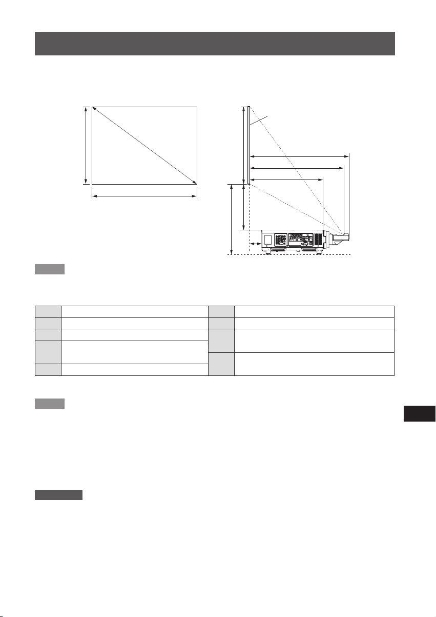
The dimensional relationship between the screen and the projector is shown below.
Dimensional relationship diagram
Projected image
Screen
SD
SH
SW
A2
SH
A1
L2
L1
L3
L4
Note
zThe indications of this illustration are premised on aligning the projected image size and position to the full screen.
zThis illustration is not drawn to scale.
SH Projected image height L3 Screen to projector front end
SW Projected image width L4 Screen to projector rear end
SD Diagonal length of the projected image
Projection distance
L1
(from screen to mirror reective surface*)
L2 Screen to lens front end
* The mirror reective surface is inside the xed-focus lens, and is not visible from the outside.
Bottom edge of the screen to the top of the
A1
projector
Bottom edge of the screen to the bottom of the
A2
projector
Note
zThe illustrations of projectors in this manual are for informational purposes only and do not represent a specic
projector model. Congurations may vary with the model.
zAfter setting the lens position using the function on the projector, the lens position can be adjusted within the
adjustment range described in "Adjustment range by the lens position shift (optical shift)" (
Then dimensions A1 and A2 will change according to lens shift amount.
zDimension L4 is the distance from the projector rear panel to the screen.
zDimension A2 is the distance from the bottom edge of the screen to the bottom of the adjustable projector legs
(with the legs fully screwed in).
Page 12).
Attention
zDimension L4 is not the distance from the projector rear panel to a wall, but the distance from the projector
rear panel to the screen. Provide at least 500 mm (19-11/16") of ventilation space between the projector rear
panel and a wall or other object.
When placing the projector in a conned space, a ventilation and/or air conditioning system is required.
Exhaust heat may accumulate when the ventilation is not sufcient triggering the protection circuit of the projector.
ENGLISH-7
Page 8
Projection relationships (continued)
Dimensional relationship
zWhen using one of PT-RZ31K / PT-RS30K / PT-RQ13K / PT-RZ12K / PT-RS11K / PT-DZ21K2 /
PT-DS20K2 / PT-DW17K2 / PT-DZ16K2 / PT-DZ13K / PT-DS12K / PT-DW11K / PT-DZ10K
For details on projection distance (L1), and A1, A2, L2, L3 and L4 values, refer to "Projected image size and
Projection distance" or "Projection distance formulas" in the Appendix.
zWhen using a projector other than one listed above
Please see "Setting up" in the operating instructions for the projector you are using.
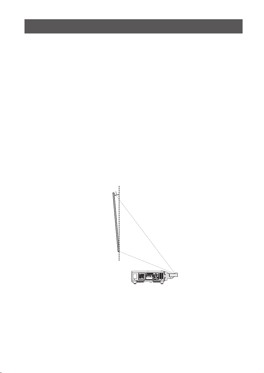
Keystone distortion correction
When attaching this lens for use, regardless of the projector model, set up the projector so that the projected
image is rectangular and the back of the projector and the screen are parallel.
In addition, depending on the projector used, keystone distortion correction may be feasible after setup.
zWhen using one of PT-RZ31K / PT-RS30K / PT-RQ13K / PT-RZ12K / PT-RS11K / PT-DZ21K2 /
PT-DS20K2 / PT-DW17K2 / PT-DZ16K2 / PT-DZ13K / PT-DS12K / PT-DZ10K
For keystone distortion in the vertical direction generated within the angle range below, select [MAIN MENU] →
[POSITION] → [GEOMETRY] → [KEYSTONE] → [VERTICAL KEYSTONE] to perform correction.
Keystone distortion in the vertical direction greater than this angle and keystone distortion in the horizontal
direction can be corrected but the projected image overall will no longer be in focus.
Correction feasible angle (α): 0 - 5°
zWhen using PT-DW11K
If keystone distortion in vertical direction or horizontal direction is corrected, the projected image overall will no
longer be in focus. Set up the projector so that the projected image is rectangular and the back of the projector
and the screen are parallel.
zWhen using a projector other than one listed above
Please see "Setting up" in the operating instructions for the projector you are using.
α
Screen
(Side view)
8-ENGLISH
Page 9
Lens position setup and focus adjustment
Lens position setup
Automatically return the lens to standard position using the projector.
The menu screens shown in these operating instructions are only provided as examples. Actual menu screens
may vary with the specic model.
● When using PT-RZ31K / PT-RS30K / PT-RQ13K / PT-RZ12K / PT-RS11K / PT-DZ21K2 / PT-DS20K2 /
PT-DW17K2 / PT-DZ16K2
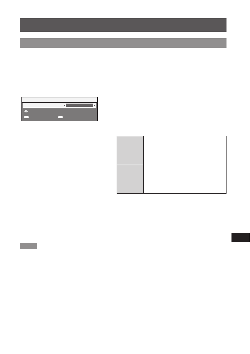
1) Turn on the projector, and start
projection.
LENS
HOME POSITION
CHANGE
ENTER
EXECUTE
2) Press the <DEF
NORMAL
the remote control while the shift
adjustment screen is displayed.
MENU
CANCEL
zThe [HOME POSITION] screen is displayed.
3) Press ◀▶ to switch the item.
zThe items will switch each time you press the button.
Moves the lens to the home position.
[NORMAL]
[D75LE95]
[D75LE90]
*1: The items displayed will differ depending on the projector
model.
Select this item when replacing or removing
the projection lens. Select this item
when the Fixed-focus Lens (Model No.:
ET-D75LE50) is used for projection.
Moves the lens to the ET-D75LE95 lens
standard position.
Select this item when the Fixed-focus
or
*1
Lens (Model No.: ET-D75LE95) is used for
projection.
AULT> button on
4) Press the <ENTER> button.
z[PROGRESS] is displayed in the [HOME POSITION]
screen, and the lens position returns to the home
position or the lens standard position.
Note
zComplete the operation within approximately 5 seconds after the [HOME POSITION] screen is displayed. The
[HOME POSITION] screen will disappear after time limit.
zThe home position of the lens is used when the lens is being replaced or when the projector is being stored,
and it is not the optical center of the screen.
zYou can also display the [HOME POSITION] screen by pressing the <LENS> button on the control panel or
the <SHIFT> button on the remote control for at least three seconds.
ENGLISH-9
Page 10
Lens position setup and focus adjustment (continued)
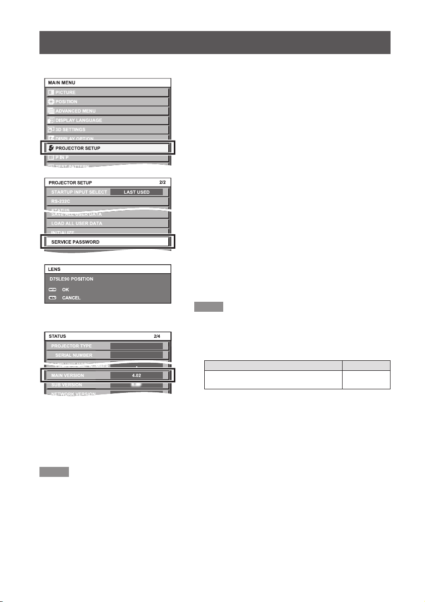
● When using PT-DZ13K / PT-DS12K / PT-DW11K / PT-DZ10K
1) Turn on the projector to start the
projection.
2) Press the <MENU> button to open
the [MAIN MENU] screen. Then select
[PROJECTOR SETUP] and press the
<ENTER> button.
3) Select [SERVICE PASSWORD] in the
[PROJECTOR SETUP] menu and press
the <ENTER> button.
4) In the [SERVICE PASSWORD] entry
screen, enter "7590" using the numeric
buttons on the remote control and then
press the <ENTER> button.
zThe [D75LE90 POSITION] screen appears.
5) Press the <ENTER> button in the [D75LE90
POSITION] screen.
z[PROGRESS] is displayed on the [D75LE90 POSITION]
screen and lens position moves to the standard position
for the ET-D75LE95.
Note
zWhen using the PT-DZ13K / PT-DS12K / PT-DW11K /
PT-DZ10K, the [MAIN VERSION] of the projector rmware
must be the version described below. Check the [MAIN
DZ13K
*1: See software download page on Panasonic website (http://panasonic.net/avc/projector/pass/). You must be a
registered PASS user to use the site described above.
PASS: Panasonic Professional Display and Projector Technical Support Website
VERSION] of the rmware on the [STATUS] screen and
upgrade the rmware version of the projector as needed. *
PT-DZ13K / PT-DS12K /
PT-DW11K / PT-DZ10K
[STATUS] screen is displayed by selecting [Main Menu]
[PROJECTOR SETUP] → [STATUS] or by pressing the
→
<STATUS> button on the remote control.
Projector
Main version
4.04 or higher
1
Note
zThe lens position set here may not match the intended standard position exactly.
zThe lens position set with this procedure will be used as the standard position. The lens position can be
adjusted within the adjustment range described in "Adjustment range by the lens position shift (optical shift)"
Page 12), even after shifting to the standard position.
(
zDepending on the (OSD) display position on the menu screen, there are cases where the projected light is
obstructed and a part of the menu is not displayed on the screen. In this case, open [MAIN MENU] → [DISPLAY
OPTIONS] → [ON-SCREEN DISPLAY] → [OSD POSITION] and change settings so that the whole OSD menu
can be seen.
10-ENGLISH
Page 11

Lens position setup and focus adjustment (continued)
Focus Adjustment Function
After setting the lens position, adjust the focus.
The focal balance between the center and periphery of the projected image changes depending on the size of the
projected image. The lens is equipped with a focus balance adjustment function for the screen periphery.
Adjusting the Focus
Lock screw
Periphery focus adjustment ring
Note
zThe projected image sizes (inches) shown on the periphery focus adjustment ring are approximate guides.
1) Focus the center of the screen by
operating the projector unit.
2) Loosen the lock screw and turn
the periphery focus adjustment
ring by hand as shown in the
gure to the left to adjust the
peripheral focus on the screen.
3) Again check focus at the center of
the screen and use the projector
controls to make ne adjustments.
4) Tighten the lock screw.
zThe periphery focus adjustment ring is locked.
ENGLISH-11
Page 12

Adjustment range by the lens position shift (optical shift)
Projected image width H
0.12 H
0.12 H
0.08H 0.08H
Projected image width H
Even after setting the lens position using "Lens position setup" noted on pages 9 and 10, the projection
position can be adjusted within respective ranges using the optical axis shift function on the projector based on
the projected image position for this lens position.
Perform the lens position shift within the adjustment range.
The focus may change when the lens position is shifted out of the adjustment range.
PT-RZ31K / PT-RZ12K
PT-RS30K / PT-RS11K
PT-RQ13K
0.07 V
0.73 V (Standard position)
Standard projection position
0.07V
0.71V (Standard position)
Standard projection position
Projected image width H
0.16H 0.16H
0.74V (Standard position)
Standard projection position
0.05 V0.05 V
Projected image height V
Projected image height V
0.04V
0.21H0.21H
0.10V
0.08V
Projected image height V
0.05V
12-ENGLISH
Page 13

0.12H 0.12H
Projected image width H
0.19H 0.19H
Projected image width H
0.08H 0.08H
Projected image width H
Projected image width H
Adjustment range by the lens position shift (optical shift) (continued)
0.05V0.07V
PT-DZ21K2 / PT-DZ13K /
PT-DZ10K
PT-DZ16K2
PT-DS20K2 / PT-DS12K
0.07V
0.74V (Standard position)
Standard projection position
0.06H 0.06H
0.08V
0.75V (Standard position)
Standard projection position
0.07V
Projected image height V
0.71V (Standard position)
Standard projection position
0.30H 0.30H
0.16H0.16H
0.07V
Projected image height V
0.13V0.08V
Projected image height V
0.18V0.09V
PT-DW17K2 / PT-DW11K
zWhen using a projector other than one listed above
Please see "Projecting" in the operating instructions for the projector you are using.
0.78V (Standard position)
Standard projection position
0.09V
Projected image height V
ENGLISH-13
Page 14

Specications
140 (5-1/2")
Ø 154 (6-1/16")
F value 2.5
Focal Length (f) 7.5 mm (9/32")
Width
Dimensions
Net Weight Approx. 5.7 kg (12.57 lb)
Height
Depth
154 mm (6-1/16")
154 mm (6-1/16")
463.5 mm (18-1/4")
Dimensions
(Unit: mm)
14-ENGLISH
Ø 154 (6-1/16")
463.5 (18-1/4")
140 (5-1/2")
132.9 (5-7/32")
Page 15

MEMO
ENGLISH-15
Page 16

Panasonic Corporation
Web Site : http://panasonic.net/avc/projector/
© Panasonic Corporation 2016
HS0916AM0 -PS
Printed in Japan
Page 17

Appendix / Annexe
■Dimensional relationship
■Relations dimensionnelles
The dimensional relationship between the screen and the projector is shown below.
Les relations dimensionnelles entre l’écran et le projecteur sont indiquées ci-dessous.
Projected image / Image projetée
Screen / Écran
SD
SH
SW
Projected image height / Hauteur de l'image projetée
SH
Projected image width / Largeur de l'image projetée
SW
Diagonal length of the projected image / Diagonale de la zone de projection
SD
Projection distance (from screen to mirror reective surface*)
L1
Distance de projection (de l’écran à la surface rééchissante du miroir*)
Screen to lens front end / De l’écran à l’extrémité avant de l’objectif
L2
Screen to projector front end / De l’écran à l’extrémité avant du projecteur
L3
Screen to projector rear end / De l’écran à l’extrémité arrière du projecteur
L4
Bottom edge of the screen to the top of the projector / Du bord inférieur de l’écran au sommet du projecteur
A1
Bottom edge of the screen to the bottom of the projector / Du bord inférieur de l’écran à la base du projecteur
A2
* The mirror reective surface is inside the xed-focus lens, and is not visible from the outside.
La surface rééchissante du miroir se trouve à l'intérieur de l'objectif à focale xe, et n'est pas visible de l'extérieur.
*
A2
SH
A1
L2
L1
L3
L4
zProjected image size and Projection distance
zTaille de l'image projetée et Distance de projection
Note
zWhen using projector models other than the following, refer to “Setting up” in the operating instructions of the projector.
Remarque
zLorsque vous utilisez des modèles de projecteur différents des modèles suivants, consultez “Installation” dans
le mode d’emploi du projecteur.
Projectors / Projecteurs
PT-RZ31K / PT-RS30K / PT-RQ13K / PT-RZ12K / PT-RS11K / PT-DZ21K2 / PT-DS20K2 / PT-DW17K2 /
PT-DZ16K2 / PT-DZ13K / PT-DS12K / PT-DW11K / PT-DZ10K
Appendix / Annexe
1
Page 18

The dimensions of the following table contain a slight error.
Periods are used to represent decimal points in the calculation formulas in the following table.
Les dimensions du tableau suivant peuvent présenter un léger écart.
Les points sont utilisés pour indiquer les décimales dans les formules de calcul dans le tableau suivant.
PT-RZ31K
z
When the screen aspect ratio is 16:10
Lorsque le rapport d’aspect de l'écran est 16:10
3.05 (120") 1.615 2.585 0.94 –0.39 0.17–0.33
3.81 (150") 2.019 3.231 1.18 –0.16 0.24–0.44
5.08 (200") 2.692 4.308 1.56 0.23 0.37–0.63
6.35 (250") 3.365 5.385 1.95 0.61 0.49–0.82
7.62 (300") 4.039 6.462 2.33 1.00 0.62–1.02
8.89 (350") 4.712 7.539 2.72 1.38 0.74–1.21
10.16 (400") 5.385 8.616 3.10 1.77 0.86–1.40
12.70 (500") 6.731 10.770 3.87 2.54 1.11–1.78
15.24 (600") 8.077 12.923 4.64 3.31 1.36–2.16
When the screen aspect ratio is 16:9
Lorsque le rapport d’aspect de l'écran est 16:9
3.05 (120") 1.494 2.657 0.97 –0.36 0.18–0.43
3.81 (150") 1.868 3.321 1.21 –0.13 0.26–0.56
5.08 (200") 2.491 4.428 1.60 0.27 0.38–0.79
6.35 (250") 3.113 5.535 2.00 0.67 0.51–1.02
7.62 (300") 3.736 6.641 2.39 1.06 0.64–1.25
8.89 (350") 4.358 7.748 2.79 1.46 0.77–1.49
10.16 (400") 4.981 8.855 3.19 1.85 0.89–1.72
12.70 (500") 6.226 11.069 3.98 2.64 1.15–2.18
15.24 (600") 7.472 13.283 4.77 3.44 1.40–2.64
When the screen aspect ratio is 4:3
Lorsque le rapport d’aspect de l'écran est 4:3
3.05 (120") 1.829 2.438 1.07 –0.27 0.21–0.39
3.81 (150") 2.286 3.048 1.33 0.00 0.29–0.52
5.08 (200") 3.048 4.064 1.76 0.43 0.43–0.74
6.35 (250") 3.810 5.080 2.20 0.87 0.57–0.95
7.62 (300") 4.572 6.096 2.64 1.30 0.71–1.17
8.89 (350") 5.334 7.112 3.07 1.74 0.85–1.38
10.16 (400") 6.096 8.128 3.51 2.17 0.99–1.60
12.70 (500") 7.620 10.160 4.38 3.05 1.27–2.03
15.24 (600") 9.144 12.192 5.25 3.92 1.55–2.46
(Throw ratio : [0.36:1])
(Rapport de projection : [0.36:1])
SD SH SW L1 L4 A1
(Throw ratio : [0.36:1])
(Rapport de projection : [0.36:1])
SD SH SW L1 L4 A1
(Throw ratio : [0.44:1])
(Rapport de projection : [0.44:1])
SD SH SW L1 L4 A1
(Unit / Unités : m)
Appendix / Annexe
2
Page 19

PT-RS30K
z
When the screen aspect ratio is 4:3
Lorsque le rapport d’aspect de l'écran est 4:3
3.05 (120") 1.829 2.438 0.96 –0.37 0.18–0.25
3.81 (150") 2.286 3.048 1.20 –0.13 0.25–0.34
5.08 (200") 3.048 4.064 1.59 0.26 0.38–0.50
6.35 (250") 3.810 5.080 1.99 0.65 0.50–0.66
7.62 (300") 4.572 6.096 2.38 1.05 0.63–0.81
8.89 (350") 5.334 7.112 2.77 1.44 0.76–0.97
10.16 (400") 6.096 8.128 3.17 1.83 0.88–1.13
12.70 (500") 7.620 10.160 3.95 2.62 1.14–1.44
15.24 (600") 9.144 12.192 4.74 3.41 1.39–1.76
(Throw ratio : [0.39:1])
(Rapport de projection : [0.39:1])
SD SH SW L1 L4 A1
(Unit / Unités : m)
W
hen the screen aspect ratio is 16:9
Lorsque le rapport d’aspect de l'écran est 16:9
SD SH SW L1 L4 A1
3.05 (120") 1.494 2.657 1.05 –0.28 0.20–0.53
3.81 (150") 1.868 3.321 1.31 –0.03 0.29–0.70
5.08 (200") 2.491 4.428 1.73 0.40 0.43–0.97
6.35 (250") 3.113 5.535 2.16 0.83 0.56–1.25
7.62 (300") 3.736 6.641 2.59 1.26 0.70–1.52
8.89 (350") 4.358 7.748 3.02 1.69 0.84–1.79
10.16 (400") 4.981 8.855 3.45 2.11 0.98–2.07
12.70 (500") 6.226 11.069 4.30 2.97 1.25–2.62
15.24 (600") 7.472 13.283 5.16 3.83 1.53–3.17
(Throw ratio : [0.39:1])
(Rapport de projection : [0.39:1])
Appendix / Annexe
3
Page 20

PT-RQ13K
z
When the screen aspect ratio is 16:10
Lorsque le rapport d’aspect de l'écran est 16:10
3.05 (120") 1.615 2.585 1.01 –0.01 0.19–0.42
3.81 (150") 2.019 3.231 1.26 0.24 0.27–0.56
5.08 (200") 2.692 4.308 1.67 0.65 0.41–0.79
6.35 (250") 3.365 5.385 2.08 1.07 0.54–1.01
7.62 (300") 4.039 6.462 2.50 1.48 0.67–1.24
8.89 (350") 4.712 7.539 2.91 1.89 0.81–1.47
10.16 (400") 5.385 8.616 3.32 2.30 0.94–1.70
12.70 (500") 6.731 10.770 4.15 3.13 1.21–2.15
15.24 (600") 8.077 12.923 4.97 3.95 1.47–2.61
(Throw ratio : [0.39:1])
(Rapport de projection : [0.39:1])
SD SH SW L1 L4 A1
(Unit / Unités : m)
When the screen aspect ratio is 16:9
Lorsque le rapport d’aspect de l'écran est 16:9
SD SH SW L1 L4 A1
3.05 (120") 1.494 2.657 1.04 0.02 0.20–0.52
3.81 (150") 1.868 3.321 1.29 0.28 0.28–0.68
5.08 (200") 2.491 4.428 1.72 0.70 0.42–0.95
6.35 (250") 3.113 5.535 2.14 1.12 0.56–1.22
7.62 (300") 3.736 6.641 2.56 1.55 0.69–1.49
8.89 (350") 4.358 7.748 2.99 1.97 0.83–1.76
10.16 (400") 4.981 8.855 3.41 2.39 0.97–2.02
12.70 (500") 6.226 11.069 4.26 3.24 1.24–2.56
15.24 (600") 7.472 13.283 5.11 4.09 1.52–3.10
When the screen aspect ratio is 4:3
Lorsque le rapport d’aspect de l'écran est 4:3
SD SH SW L1 L4 A1
3.05 (120") 1.829 2.438 1.14 0.12 0.23–0.49
3.81 (150") 2.286 3.048 1.42 0.40 0.33–0.65
5.08 (200") 3.048 4.064 1.89 0.87 0.48–0.91
6.35 (250") 3.810 5.080 2.36 1.34 0.63–1.16
7.62 (300") 4.572 6.096 2.82 1.81 0.78–1.42
8.89 (350") 5.334 7.112 3.29 2.27 0.93–1.68
10.16 (400") 6.096 8.128 3.76 2.74 1.08–1.94
12.70 (500") 7.620 10.160 4.69 3.67 1.38–2.46
15.24 (600") 9.144 12.192 5.62 4.61 1.68–2.97
(Throw ratio : [0.39:1])
(Rapport de projection : [0.39:1])
(Throw ratio : [0.47:1])
(Rapport de projection : [0.47:1])
Appendix / Annexe
4
Page 21

PT-RZ12K
z
When the screen aspect ratio is 16:10
Lorsque le rapport d’aspect de l'écran est 16:10
3.05 (120") 1.615 2.585 0.94 –0.07 0.17–0.33
3.81 (150") 2.019 3.231 1.18 0.16 0.24–0.44
5.08 (200") 2.692 4.308 1.56 0.54 0.37–0.63
6.35 (250") 3.365 5.385 1.95 0.93 0.49–0.82
7.62 (300") 4.039 6.462 2.33 1.31 0.62–1.02
8.89 (350") 4.712 7.539 2.72 1.70 0.74–1.21
10.16 (400") 5.385 8.616 3.10 2.08 0.86–1.40
12.70 (500") 6.731 10.770 3.87 2.85 1.11–1.78
15.24 (600") 8.077 12.923 4.64 3.62 1.36–2.16
(Throw ratio : [0.36:1])
(Rapport de projection : [0.36:1])
SD SH SW L1 L4 A1
(Unit / Unités : m)
When the screen aspect ratio is 16:9
Lorsque le rapport d’aspect de l'écran est 16:9
SD SH SW L1 L4 A1
3.05 (120") 1.494 2.657 0.97 –0.05
3.81 (150") 1.868 3.321 1.21 0.19
5.08 (200") 2.491 4.428 1.60 0.59
6.35 (250") 3.113 5.535 2.00 0.98
7.62 (300") 3.736 6.641 2.39 1.38
8.89 (350") 4.358 7.748 2.79 1.77
10.16 (400") 4.981 8.855 3.19 2.17
12.70 (500") 6.226 11.069 3.98 2.96
15.24 (600") 7.472 13.283 4.77 3.75
When the screen aspect ratio is 4:3
Lorsque le rapport d’aspect de l'écran est 4:3
SD SH SW L1 L4 A1
3.05 (120") 1.829 2.438 1.07 0.05 0.21–0.39
3.81 (150") 2.286 3.048 1.33 0.31 0.29–0.52
5.08 (200") 3.048 4.064 1.76 0.75 0.43–0.74
6.35 (250") 3.810 5.080 2.20 1.18 0.57–0.95
7.62 (300") 4.572 6.096 2.64 1.62 0.71–1.17
8.89 (350") 5.334 7.112 3.07 2.05 0.85–1.38
10.16 (400") 6.096 8.128 3.51 2.49 0.99–1.60
12.70 (500") 7.620 10.160 4.38 3.36 1.27–2.03
15.24 (600") 9.144 12.192 5.25 4.23 1.55–2.46
(Throw ratio : [0.36:1])
(Rapport de projection : [0.36:1])
0.18–0.43
0.26–0.56
0.38–0.79
0.51–1.02
0.64–1.25
0.77–1.49
0.89–1.72
1.15–2.18
1.40–2.64
(Throw ratio : [0.44:1])
(Rapport de projection : [0.44:1])
Appendix / Annexe
5
Page 22

PT-RS11K
z
When the screen aspect ratio is 4:3
Lorsque le rapport d’aspect de l'écran est 4:3
3.05 (120") 1.829 2.438 0.96 –0.05
3.81 (150") 2.286 3.048 1.20 0.18
5.08 (200") 3.048 4.064 1.59 0.58
6.35 (250") 3.810 5.080 1.99 0.97
7.62 (300") 4.572 6.096 2.38 1.36
8.89 (350") 5.334 7.112 2.77 1.76
10.16 (400") 6.096 8.128 3.17 2.15
12.70 (500") 7.620 10.160 3.95 2.94
15.24 (600") 9.144 12.192 4.74 3.72
(Throw ratio : [0.39:1])
(Rapport de projection : [0.39:1])
SD SH SW L1 L4 A1
(Unit / Unités : m)
0.18–0.25
0.25–0.34
0.38–0.50
0.50–0.66
0.63–0.81
0.76–0.97
0.88–1.13
1.14–1.44
1.39–1.76
When the screen aspect ratio is 16:9
Lorsque le rapport d’aspect de l'écran est 16:9
SD SH SW L1 L4 A1
3.05 (120") 1.494 2.657 1.05 0.03
3.81 (150") 1.868 3.321 1.31 0.29
5.08 (200") 2.491 4.428 1.73 0.72
6.35 (250") 3.113 5.535 2.16 1.15
7.62 (300") 3.736 6.641 2.59 1.57
8.89 (350") 4.358 7.748 3.02 2.00
10.16 (400") 4.981 8.855 3.45 2.43
12.70 (500") 6.226 11.069 4.30 3.29
15.24 (600") 7.472 13.283 5.16 4.14
(Throw ratio : [0.39:1])
(Rapport de projection : [0.39:1])
0.20–0.53
0.29–0.70
0.43–0.97
0.56–1.25
0.70–1.52
0.84–1.79
0.98–2.07
1.25–2.62
1.53–3.17
Appendix / Annexe
6
Page 23

PT-DZ21K2 / PT-DZ13K / PT-DZ10K
z
When the screen aspect ratio is 16:10
Lorsque le rapport d’aspect de l'écran est 16:10
SD SH SW L1
3.05 (120") 1.615 2.585 0.94 –0.08 0.11 0.14–0.34 0.15–0.36
3.81 (150") 2.019 3.231 1.18 0.15 0.34 0.20–0.46 0.21–0.47
5.08 (200") 2.692 4.308 1.56 0.54 0.73 0.30–0.65 0.32–0.66
6.35 (250") 3.365 5.385 1.95 0.92 1.11 0.40–0.84 0.42–0.85
7.62 (300") 4.039 6.462 2.33 1.31 1.50 0.51–1.03 0.52–1.04
8.89 (350") 4.712 7.539 2.72 1.69 1.88 0.61–1.22 0.63–1.23
10.16 (400") 5.385 8.616 3.10 2.08 2.27 0.72–1.41 0.73–1.42
12.70 (500") 6.731 10.770 3.87 2.85 3.04 0.92–1.79 0.94–1.81
15.24 (600") 8.077 12.923 4.64 3.62 3.81 1.13–2.17 1.14–2.19
(Throw ratio : [0.36:1])
(Rapport de projection : [0.36:1])
L4 A1
PT-DZ21K2
PT-DZ13K /
PT-DZ10K
PT-DZ21K2
(Unit / Unités : m)
PT-DZ13K /
PT-DZ10K
When the screen aspect ratio is 16:9
Lorsque le rapport d’aspect de l'écran est 16:9
SD SH SW L1
3.05 (120") 1.494 2.657 0.97 –0.05 0.14 0.14–0.44 0.16–0.45
3.81 (150") 1.868 3.321 1.21 0.19 0.38 0.21–0.58 0.22–0.59
5.08 (200") 2.491 4.428 1.60 0.58 0.77 0.31–0.81 0.33–0.82
6.35 (250") 3.113 5.535 2.00 0.98 1.17 0.42–1.04 0.44–1.05
7.62 (300") 3.736 6.641 2.39 1.37 1.56 0.53–1.27 0.54–1.28
8.89 (350") 4.358 7.748 2.79 1.77 1.96 0.64–1.50 0.65–1.51
10.16 (400") 4.981 8.855 3.19 2.16 2.35 0.74–1.73 0.76–1.74
12.70 (500") 6.226 11.069 3.98 2.96 3.15 0.96–2.19 0.97–2.20
15.24 (600") 7.472 13.283 4.77 3.75 3.94 1.17–2.65 1.19–2.66
When the screen aspect ratio is 4:3
Lorsque le rapport d’aspect de l'écran est 4:3
SD SH SW L1
3.05 (120") 1.829 2.438 1.07 0.06 0.25 0.17–0.40 0.18–0.42
3.81 (150") 2.286 3.048 1.33 0.32 0.51 0.24–0.53 0.25–0.55
5.08 (200") 3.048 4.064 1.76 0.76 0.95 0.36–0.75 0.37–0.76
6.35 (250") 3.810 5.080 2.20 1.19 1.38 0.47–0.96 0.49–0.98
7.62 (300") 4.572 6.096 2.64 1.63 1.82 0.59–1.18 0.60–1.19
8.89 (350") 5.334 7.112 3.07 2.06 2.25 0.71–1.40 0.72–1.41
10.16 (400") 6.096 8.128 3.51 2.50 2.69 0.83–1.61 0.84–1.63
12.70 (500") 7.620 10.160 4.38 3.37 3.56 1.06–2.04 1.07–2.06
15.24 (600") 9.144 12.192 5.25 4.24 4.43 1.29–2.47 1.31–2.49
(Throw ratio : [0.36:1])
(Rapport de projection : [0.36:1])
PT-DZ21K2
(Throw ratio : [0.44:1])
(Rapport de projection : [0.44:1])
PT-DZ21K2
L4 A1
PT-DZ13K /
PT-DZ10K
L4 A1
PT-DZ13K /
PT-DZ10K
PT-DZ21K2
PT-DZ21K2
PT-DZ13K /
PT-DZ10K
PT-DZ13K /
PT-DZ10K
Appendix / Annexe
7
Page 24

PT-DZ16K2
z
When the screen aspect ratio is 16:9
Lorsque le rapport d’aspect de l'écran est 16:9
3.05 (120") 1.494 2.657 0.97 –0.05 0.14–0.44
3.81 (150") 1.868 3.321 1.21 0.19 0.21–0.58
5.08 (200") 2.491 4.428 1.60 0.58 0.31–0.81
6.35 (250") 3.113 5.535 2.00 0.98 0.42–1.04
7.62 (300") 3.736 6.641 2.39 1.37 0.53–1.27
8.89 (350") 4.358 7.748 2.79 1.77 0.64–1.50
10.16 (400") 4.981 8.855 3.19 2.16 0.74–1.73
12.70 (500") 6.226 11.069 3.98 2.96 0.96–2.19
15.24 (600") 7.472 13.283 4.77 3.75 1.17–2.65
(Throw ratio : [0.36:1])
(Rapport de projection : [0.36:1])
SD SH SW L1 L4 A1
(Unit / Unités : m)
When the screen aspect ratio is 4:3
Lorsque le rapport d’aspect de l'écran est 4:3
SD SH SW L1 L4 A1
3.05 (120") 1.829 2.438 1.18 0.16 0.20–0.56
3.81 (150") 2.286 3.048 1.47 0.45 0.28–0.73
5.08 (200") 3.048 4.064 1.96 0.94 0.41–1.01
6.35 (250") 3.810 5.080 2.44 1.42 0.54–1.30
7.62 (300") 4.572 6.096 2.93 1.90 0.67–1.58
8.89 (350") 5.334 7.112 3.41 2.39 0.80–1.86
10.16 (400") 6.096 8.128 3.89 2.87 0.94–2.14
12.70 (500") 7.620 10.160 4.86 3.84 1.20–2.71
15.24 (600") 9.144 12.192 5.83 4.81 1.46–3.27
(Throw ratio : [0.48:1])
(Rapport de projection : [0.48:1])
Appendix / Annexe
8
Page 25

PT-DS20K2 / PT-DS12K
z
When the screen aspect ratio is 4:3
Lorsque le rapport d’aspect de l'écran est 4:3
SD SH SW L1
3.05 (120") 1.829 2.438 0.96 –0.06 0.13
3.81 (150") 2.286 3.048 1.20 0.18 0.37
5.08 (200") 3.048 4.064 1.59 0.57 0.76
6.35 (250") 3.810 5.080 1.99 0.96 1.15
7.62 (300") 4.572 6.096 2.38 1.36 1.55
8.89 (350") 5.334 7.112 2.77 1.75 1.94
10.16 (400") 6.096 8.128 3.17 2.14 2.33
12.70 (500") 7.620 10.160 3.95 2.93 3.12
15.24 (600") 9.144 12.192 4.74 3.72 3.91
(Throw ratio : [0.39:1])
(Rapport de projection : [0.39:1])
L4 A1
PT-DS20K2 PT-DS12K PT-DS20K2 PT-DS12K
(Unit / Unités : m)
0.14–0.26
0.20–0.36
0.31–0.51
0.42–0.67
0.52–0.83
0.63–0.99
0.73–1.14
0.95–1.46
1.16–1.77 1.17–1.78
0.15–0.28
0.22–0.37
0.32–0.53
0.43–0.69
0.54–0.84
0.64–1.00
0.75–1.16
0.96–1.47
When the screen aspect ratio is 16:9
Lorsque le rapport d’aspect de l'écran est 16:9
SD SH SW L1
3.05 (120") 1.494 2.657 1.05 0.03 0.22
3.81 (150") 1.868 3.321 1.31 0.28 0.47
5.08 (200") 2.491 4.428 1.73 0.71 0.90
6.35 (250") 3.113 5.535 2.16 1.14 1.33
7.62 (300") 3.736 6.641 2.59 1.57 1.76
8.89 (350") 4.358 7.748 3.02 2.00 2.19
10.16 (400") 4.981 8.855 3.45 2.43 2.62
12.70 (500") 6.226 11.069 4.30 3.28 3.47
15.24 (600") 7.472 13.283 5.16 4.14 4.33
(Throw ratio : [0.39:1])
(Rapport de projection : [0.39:1])
L4 A1
PT-DS20K2 PT-DS12K PT-DS20K2 PT-DS12K
0.16–0.55 0.18–0.56
0.23–0.71 0.25–0.72
0.35–0.98 0.36–1.00
0.47–1.26 0.48–1.27
0.58–1.53 0.60–1.55
0.70–1.81 0.71–1.82
0.81–2.08 0.83–2.10
1.04–2.63 1.06–2.65
1.28–3.18 1.29–3.20
Appendix / Annexe
9
Page 26

PT-DW17K2 / PT-DW11K
z
When the screen aspect ratio is 16:9
Lorsque le rapport d’aspect de l'écran est 16:9
SD SH SW L1
3.05 (120") 1.494 2.657 1.07 0.05 0.24 0.17–0.58 0.18–0.60
3.81 (150") 1.868 3.321 1.34 0.32 0.51 0.24–0.76 0.26–0.77
5.08 (200") 2.491 4.428 1.78 0.75 0.94 0.36–1.05 0.37–1.06
6.35 (250") 3.113 5.535 2.22 1.19 1.38 0.48–1.34 0.49–1.35
7.62 (300") 3.736 6.641 2.66 1.63 1.82 0.60–1.63 0.61–1.64
8.89 (350") 4.358 7.748 3.09 2.07 2.26 0.71–1.92 0.73–1.93
10.16 (400") 4.981 8.855 3.53 2.51 2.70 0.83–2.21 0.85–2.22
12.70 (500") 6.226 11.069 4.41 3.39 3.58 1.07–2.79 1.08–2.80
15.24 (600") 7.472 13.283 5.29 4.27 4.46 1.31–3.37 1.32–3.38
(Throw ratio : [0.40:1])
(Rapport de projection : [0.40:1])
L4 A1
PT-DW17K2 PT-DW11K PT-DW17K2 PT-DW11K
(Unit / Unités : m)
When the screen aspect ratio is 4:3
Lorsque le rapport d’aspect de l'écran est 4:3
SD SH SW L1
3.05 (120") 1.829 2.438 1.31 0.29 0.48 0.23–0.74 0.25–0.75
3.81 (150") 2.286 3.048 1.63 0.61 0.80 0.32–0.95 0.33–0.97
5.08 (200") 3.048 4.064 2.17 1.15 1.34 0.47–1.31 0.48–1.32
6.35 (250") 3.810 5.080 2.71 1.69 1.88 0.61–1.66 0.62–1.68
7.62 (300") 4.572 6.096 3.25 2.22 2.41 0.76–2.02 0.77–2.03
8.89 (350") 5.334 7.112 3.78 2.76 2.95 0.90–2.37 0.91–2.39
10.16 (400") 6.096 8.128 4.32 3.30 3.49 1.04–2.73 1.06–2.74
12.70 (500") 7.620 10.160 5.40 4.37 4.56 1.33–3.44 1.35–3.45
15.24 (600") 9.144 12.192 6.47 5.45 5.64 1.62–4.15 1.64–4.16
(Throw ratio : [0.54:1])
(Rapport de projection : [0.54:1])
L4 A1
PT-DW17K2 PT-DW11K PT-DW17K2 PT-DW11K
Note
zThe listed projection distances involve an error of ±5%.
z"GEOMETRY" and "VERTICAL KEYSTONE" tend to correct the projected image to a size that is smaller than
regular size.
zThrow ratio is based on the value during projection onto a 3.81 m (150") screen.
Remarque
zLes distances de projection dans la liste implique une erreur de ±5 %.
zLe “GÉOMÉTRIE” et la “TRAPÈZE VERTICAL” ont tendance à corriger l’image projetée à une taille inférieure
à la taille normale.
zLe rapport de projection (throw) se base sur la valeur pendant la projection sur un écran de 3,81 m (150").
Appendix / Annexe
10
Page 27

zProjection distance formulas
zFormules de distance de projection
If you are using a projection screen size not listed in these Operating Instructions, measure the diagonal screen
size SD (m). Then use the calculation methods provided to determine projection distance (L1) and the distance
from the top of the projector to the bottom edge of the screen (A1).
Establishing dimensions L1 and A1 allows you to calculate all other dimensions.
Note that the values obtained in the following calculations are approximations.
Si vous utilisez une taille d’écran de projection n’apparaissant pas dans la liste de ce mode d’emploi, mesurez la
taille de l’écran en diagonale SD (m). Utilisez ensuite les méthodes de calcul fournies pour déterminer la distance
de projection (L1) et la distance du sommet du projecteur au bord inférieur de l’écran (A1).
Établir les dimensions L1 et A1 vous permet de calculer toutes les autres dimensions.
Notez que les valeurs obtenues dans les calculs suivants sont des approximations.
PT-RZ31K
z
Rapport d’aspect
PT-RS30K
z
Rapport d’aspect
PT-RQ13K
z
Rapport d’aspect
PT-RZ12K
z
Rapport d’aspect
Aspect ratio
16 : 10 = 0.303 × SD + 0.020 = 0.184 × SH – 0.128 = 0.283 × SH – 0.128
16 : 9 = 0.312 × SD + 0.020 = 0.205 × SH – 0.128 = 0.370 × SH – 0.128
4 : 3 = 0.343 × SD + 0.020 = 0.184 × SH – 0.128 = 0.283 × SH – 0.128
Aspect ratio
4 : 3 = 0.310 × SD + 0.020 = 0.166 × SH – 0.128 = 0.206 × SH – 0.128
16 : 9 = 0.337 × SD + 0.020 = 0.222 × SH – 0.128 = 0.441 × SH – 0.128
Aspect ratio
16 : 10 = 0.325 × SD + 0.020 = 0.198 × SH – 0.128 = 0.339 × SH – 0.128
16 : 9 = 0.334 × SD + 0.020 = 0.220 × SH – 0.128 = 0.432 × SH – 0.128
4 : 3 = 0.368 × SD + 0.020 = 0.198 × SH – 0.128 = 0.339 × SH – 0.128
Aspect ratio
16 : 10 = 0.303 × SD + 0.020 = 0.184 × SH – 0.128 = 0.283 × SH – 0.128
16 : 9 = 0.312 × SD + 0.020 = 0.205 × SH – 0.128 = 0.370 × SH – 0.128
4 : 3 = 0.343 × SD + 0.020 = 0.184 × SH – 0.128 = 0.283 × SH – 0.128
L1
L1
L1
L1
Min. / Mini Max. / Maxi
Min. / Mini Max. / Maxi
Min. / Mini Max. / Maxi
Min. / Mini Max. / Maxi
A1
A1
A1
A1
(Unit / Unités : m)
PT-RS11K
z
Rapport d’aspect
Aspect ratio
4 : 3 = 0.310 × SD + 0.020 = 0.166 × SH – 0.128 = 0.206 × SH – 0.128
16 : 9 = 0.337 × SD + 0.020 = 0.222 × SH – 0.128 = 0.441 × SH – 0.128
L1
Min. / Mini Max. / Maxi
A1
Appendix / Annexe
11
Page 28

PT-DZ21K2 / PT-DZ13K / PT-DZ10K
z
Aspect ratio
Rapport
d’aspect
PT-DZ21K2
PT-DZ13K / PT-DZ10K = 0.154 × SH – 0.100 = 0.283 × SH – 0.100
PT-DZ21K2
PT-DZ13K / PT-DZ10K = 0.172 × SH – 0.100 = 0.370 × SH – 0.100
PT-DZ21K2
PT-DZ13K / PT-DZ10K = 0.154 × SH – 0.100 = 0.283 × SH – 0.100
16 : 10
16 : 9
4 : 3
L1
= 0.303 × SD + 0.020
= 0.312 × SD + 0.020
= 0.343 × SD + 0.020
(Unit / Unités : m)
A1
Min. / Mini Max. / Maxi
= 0.154 × SH – 0.114 = 0.283 × SH – 0.114
= 0.172 × SH – 0.114 = 0.370 × SH – 0.114
= 0.154 × SH – 0.114 = 0.283 × SH – 0.114
PT-DZ16K2
z
Aspect ratio
Rapport d’aspect
PT-DS20K2 / PT-DS12K
z
PT-DS20K2
PT-DS12K
PT-DS20K2
PT-DS12K
PT-DW17K2 / PT-DW11K
z
PT-DW17K2
PT-DW11K
PT-DW17K2
PT-DW11K
L1
16 : 9 = 0.312 × SD + 0.020 = 0.172 × SH – 0.114 = 0.370 × SH – 0.114
4 : 3 = 0.381 × SD + 0.020 = 0.172 × SH – 0.114 = 0.370 × SH – 0.114
Aspect ratio
Rapport
d’aspect
4 : 3
16 : 9
Aspect ratio
Rapport
d’aspect
16 : 9
4 : 3
L1
= 0.310 × SD + 0.020
= 0.337 × SD + 0.020
L1
= 0.346 × SD + 0.020
= 0.423 × SD + 0.020
Min. / Mini Max. / Maxi
Min. / Mini Max. / Maxi
= 0.139 × SH – 0.114 = 0.206 × SH – 0.114
= 0.186 × SH – 0.114 = 0.441 × SH – 0.114
= 0.186 × SH – 0.100 = 0.441 × SH – 0.100
Min. / Mini Max. / Maxi
= 0.190 × SH – 0.114 = 0.466 × SH – 0.114
= 0.190 × SH – 0.100 = 0.466 × SH – 0.100
= 0.190 × SH – 0.114 = 0.466 × SH – 0.114
= 0.190 × SH – 0.100 = 0.466 × SH – 0.100
A1
A1
= 0.206 × SH – 0.100
A1
Appendix / Annexe
12
Page 29

zCalculation method for L2, L3, L4 and A2
Méthode de calcul pour L2, L3, L4 et A2
L2 L3 L4 A2
PT-RZ31K / PT-RS30K
PT-RQ13K / PT-RZ12K /
PT-RS11K
PT-DZ21K2 / PT-DS20K2 /
PT-DW17K2 / PT-DZ16K2
PT-DZ13K / PT-DS12K /
PT-DW11K / PT-DZ10K
= L1 + 0.0287 = L1 – 0.262 = L1 – 1.332 = A1 + 0.419
= L1 + 0.0287 = L1 – 0.292
= L1 – 1.017 = A1 + 0.324
= L1 – 1.022 = A1 + 0.291
= L1 – 0.832 = A1 + 0.200
(Unit / Unités :
m)
Appendix / Annexe
13
Page 30

MEMO
Appendix / Annexe
14
Page 31

MEMO
Appendix / Annexe
15
Page 32

Panasonic Corporation
Web Site : http://panasonic.net/avc/projector/
© Panasonic Corporation 2016
HS0916AM0 -PS
Printed in Japan
 Loading...