

Panasonic EQ-500 Series Instruction Manual
Thank you very much for using SUNX products. Please
read this Instruction Manual carefully and thoroughly for
the correct and optimum use of this product. Kindly keep
this manual in a convenient place for quick reference.
INSTRUCTION MANUAL
Photoelectric Sensor
Adjustable Range Reflective
EQ-500 Series
1
SPECIFICATIONS
Type
Item With timer
Adjustable range (Note 1) (Note 2)
Sensing range (Setting dis-
tance maximum) (Note 2)
Hysteresis (Note 2)
Power / Current
consumption
Output
Response time
Operation indicator
Stability indicator
Distance adjuster
Sensing mode
Timer function
Automatic interference
prevention function
Protection
Ambient temperature
Ambient humidity
Emitting element
Receiving element
Material
Connection method
Cable
Cable length
Weight
Accessory
Notes: 1)
2
Model No.
Output operation
Short-circuit protection
The adjustable range stands for the maximum sensing range which can be set with the adjuster.
2)
The adjustable range, the sensing range and the hysteresis are specified for white non-glossy paper (200200mm) as the object.
3)
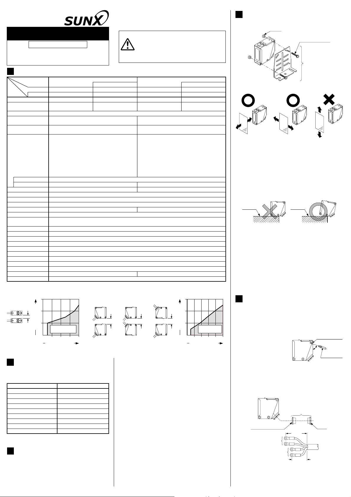
When the sensors are mounted closely, use them in the interference prevented area, as shown below.
3
2
1
L mm
Setting range (m)
or more
06020 8040
Note that the detection may be unstable depending on the mounting conditions or the sensing object. In the state where this product is mounted, be sure to check the operation with the actual sensing object to be used.
Mounting interval L (mm)
INFORMATION RELATING TO
EQ-501
EQ-501T
0.2 to 2.5m 0.2 to 1.0m
24 to 240V AC r 10% or 12 to 240V DC r 10%
Ripple P-P 10% or less
AC: 4VA or less (With timer: 5VA or less)
DC: 3W or less (With timer: 4W or less)
Relay contact 1a
Switching capacity: 250V AC 3A (resistive load)
Electrical life: 100,000 or more operations
Mechanical life: 50,000,000 or more operations
20ms or less (Depends on the timer setting period for EQ-50غT)
Interference
prevented area
LOW VOLTAGE DIRECTIVE
(Multi-voltage type only)
Item
Impulse withstanding voltage
Rated conditional protective device
Note: Each condition for use that the standards require is under
less than 2,000m above sea level.
3
CAUTIONS
٨
Make sure that the power supply is off while wiring and adjusting.
Take care that wrong wiring will damage the sensor.
٨
Verify that the supply voltage variation is within the rating.
٨
If power is supplied from a commercial switching reg-
٨
ulator, ensure that the frame ground (F.G.) terminal of
the power supply is connected to an actual ground.
FUSE 5A FAST BLOWShort-circuit protective device
Multi-voltage
Short sensing range
EQ-502
EQ-502T
10% or less of operation distance
30V DC 3A (resistive load)
(switching frequency 1,200 times/hour)
(switching frequency 18,000 times/hour)
Switchable either Detection-ON or Detection-OFF
㧙
Orange LED (lights up when the output is ON)
Green LED (lights up under stable operating condition)
2-turn mechanical adjuster with pointer
㧙
EQ-5غT: Selectable from ON-delay and OFF-delay (0.1 to 5 sec. variable)
-25 to +55 (No dew condensation or icing allowed), Storage: -30 to +70
Enclosure: ABS, Front cover: Polycarbonate, Display cover: Polycarbonate
Extension up to total 100m is possible with 0.3mm
100g approx. 85g approx.
Description
IEC 60947-5-2: 1998Refering standard
AC-12/DC-12Utilaization category
2.5kV
3Pollution degree
25HzFrequency of operation cycle
20msTurn off time
12%Excess gain
100A
35 to 85% RH, Storage: 35 to 85% RH
Infrared LED (modulated)
2-segment photodiode
Screw-on terminal connection
Suitable for round cable Ǿ9 toǾ11mm
Adjusting screwdriver: 1 pc.
L mm
or more
٨٨Never use this product as a sensing
device for personnel protection.
In case of using sensing devices for personnel
WARNING
Incorporated (Note 3)
٨
٨
٨
٨
٨
٨
٨
٨
٨
٨
٨
protection, use products which meet standards,
such as OSHA, ANSI or IEC etc., for personnel
protection applicable in each region or country.
DC-voltage
EQ-511
EQ-511T
0.2 to 2.5m 0.2 to 1.0m
0.1 to 2.5m 0.1 to 1.0m0.1 to 2.5m 0.1 to 1.0m
12 to 24V DCr10%˴Ripple P-P 10% or lessSupply voltage
NPN open-collector transistor
Maximum sink current: 100mA
Applied voltage: 30V DC or less (between output and 0V)
Residual voltage: 1V or less (at 100mA sink current)
PNP open-collector transistor
Maximum source current: 100mA
Applied voltage: 30V DC or less (between output and +V)
Residual voltage: 1V or less (at 100mA source current)
2ms or less (Depends on the timer setting period for EQ-51غT)
IP67 (IEC)
L mm
or more
Do not run the wires together with high-voltage lines or
power lines or put them in the same raceway. This can
cause malfunction due to induction.
In case noise generating equipment (switching regulator, inverter motor, etc.) is used in the vicinity of this
product, connect the frame ground (F.G.) terminal of
the equipment to an actual ground.
Take care that the sensor is not directly exposed to fluorescent light from a rapid-starter lamp or a high frequency
lighting device, as it may affect the sensing performance.
If an external surge voltage exceeding 4kV (DC-voltage:
1kV) is impressed, the internal circuit will be damaged,
and a surge suppressing element should be used.
Do not use during the initial transient time (50ms) after
the power supply is switched on.
This sensor is suitable for indoor use only.
A mechanical structure is employed for the distance adjuster of this product. Take care not to drop the product.
Do not use this sensor in places having excessive vapor, dust, etc., or where it may come in direct contact
with water, or corrosive gas.
Take care that the sensor does not come in direct contact with water, oil, grease, or organic solvents, such
as, thinner, etc.
This sensor cannot be used in an environment containing inflammable or explosive gases.
Never disassemble or modify the sensor.
0.4V or less (at 16mA source current)
Switch either BGS or FGS function
2
, or more, cabtyre cable
L mm
or more
Short sensing range
45mA or less
0.4V or less (at 16mA sink current)
Incorporated
3
2
1
Setting range (m)
0
Mounting interval L (mm)
EQ-512
EQ-512T
Interference
prevented area
150 20050250100
4
MOUNTING
٨ The tightening torque should be 0.8N㨯m or less.
M5 PWV
M5 (length 32mm)
screw with washers
Sensor
mounting
bracket
MS-EQ5-01
(Optional)
٨
Care must be taken regarding the sensor mounting direction with respect to the object's direction of movement.
Sensing object Sensing object
٨٨When detecting a specular object (aluminum or copper
foil, etc.) or an object having a glossy surface or coating, please take care that there are cases when the
object may not be detected due to a small change in
angle, wrinkles on the object surface, etc.
When a specular body is present below the sensor,
use the sensor by tiling it slightly upwards to avoid
wrong operation.
Specular
face
٨
If a specular body is present in the background, wrong
operation may be caused due to a small change in the
angle of the background body. In that case, install the
sensor at an inclination and confirm the operation with
the actual sensing object.
This product is not easily affected by the reflected light in-
٨
tensity since this sensor is the adjustable range reflective
type. When the reflected light intensity is remarkably low, the
sensing range may be affected. In that case, mount the sensor, while checking light-up of the stable indicator (green).
Mounting screws of the terminal cover and display cov-
٨
er should certainly be tightened to maintain the water
tight rating, however, the tightening torque of the
screws should be of 0.3 to 0.5N㨯m.
5
WIRING CONNECTIONS
٨٨Check all wiring before applying power since incorrect
wiring may damage the internal circuit.
Also, carefully tighten the terminal screws so that the
wires of adjacent terminals do not touch.
The mounting hole for screw the terminal cover fixing
inclines 70 degrees to the
terminal cover, as shown
in the figure below.
To avoid damaging this
product or a screw, take
care when tightening or
loosening a screw.
٨To maintain a watertight performance, the cable should
have an outer diameter between Ǿ9 to Ǿ11mm with a
smooth covering material that allows the accessory conduit connector to be securely tightened, however, the tightening torque of the screw should be of 1.5 to 2.0N㨯m.
Composition of a conduit connector, and processing of a cable
Gland packing (Note)
Power supply
Note:
When assembling the conduit connector, take care of the
direction of the gland packing.
Furthermore, in order to maintain a watertight performance, fit
the gland packing such that the seating surface of the gland
packing contacts the packing holder part of the terminal cover
Conduit connector
Output
Specular
face
37mm
25mm
Sensing object
Do not make the sensor detect an object
in this direction because it may cause
unstable operation.
Tilt
Screw for terminal
cover fixing
70q
Screwdriver
Gland
٨If pressure terminals are to be used, affix the connect-
ed pressure terminals to a terminal (M3.5 screw).
Dimensions of the suitable crimp terminals
(Unit: mm)
Round type Y-shaped type
22 or less
Ǿ3.6
or more
7.5
or less
The tightening torque of the terminal screws should be
0.3 to 0.5N㨯m.
6
I/O CIRCUIT DIAGRAMS
10
or less
17
or less
(After crimping)
٨ Multi-voltage type
Multi-voltage
circuit
Output relay
Sensor circuit
Internal circuit
٨ DC-voltage type
D
ZD2
Tr2
Sensor circuit
T
r1
ZD1
Internal circuit Users' circuit
Symbols...D: Reverse supply polarity protection diode
D1, ZD2: Surge absorption zener diode
Z
r1: NPN output transistor
T
r2: PNP output transistor
T
Ǿ3.6
or more
7
7.5
or less
or less
Terminal No.
Power supply
24 to 240V ACr10%
12 to 240V DCr10%
Relay contact
(1a)
Terminal No.
+V
100mA max.
Output (PNP)
Output (NPN)
0V
or
Load
100mA max.
22 or less
10
or less
17
or less
(After crimping)
Load
+
-
7
or less
12 to 24V DC
r10%
٨ Terminal position
Ԙ
Ԛ
7
PART DESCRIPTION
Stability indicator (Green)
Distance adjuster
(2-turn)
Adjuster indicator
Operation indicator (Orange)
Notes: 1)
The operation mode switch of the DC-voltage type is the
DIP switch. Refer to ' OPERATION MODE SWITCH' for
details.
2)
Incorporated on EQ-5غT only.
8
OPERATION MODE SWITCH
8
ԙ
ԛ
OFF-delay timer switch
(Note 2)
ON-delay timer switch
(Note 2)
Operation mode switch (Note 1)
٨ Multi-voltage type (L-ON / D-ON mode only)
Operation mode switch
Detection-ON mode is obtained when the
switch is turned fully clockwise.
Detection-OFF mode is obtained when the
switch is turned fully counterclockwise.
Note: Turn the operation mode switch gradually and lightly with the
attached screwdriver. If the distance adjuster is over turned or
pressed heavily, it may be damaged.
Description
٨ DC-voltage type
L-ON / D-ON mode
BGS/FGS mode
Timer mode
Not used
LD
BGS FGS
OFF
Timer ON
N.C.N.C.
9
BGS/FGS FUNCTION
(DC-voltage type only)
٨٨This sensor incorporates BGS/FGS function. Select
either BGS or FGS function depending on the positions of the background and sensing object.
BGS/FGS function is set with the operation mode
switch.
Depends on a selection of either BGS or FGS function, the output operation changes as follows.
Sensing range
Non-detectable area
L-ON
BGS
D-ON
L-ON
FGS
D-ON
<BGS function>
This function is used when
٨
the sensing object is apart
from the background.
<FGS function>
٨ This function is used when the sensing
object contacts the background or the
sensing object is glossy, etc.
10
DISTANCE ADJUSTMENT
For DC-voltage type, be sure to set the BGS/FGS function before distance adjustment. If the setting is done after the distance adjustment, the sensing area is changed.
٨ Turn the distance adjuster gradually and lightly with a
screwdriver (please arrange separately). In order to
protect itself, the distance adjuster idles if turned fully.
٨ Multi-voltage type, DC-voltage typeBGS select
Step
Turn the distance adjuster fully counterclockwise to the minimum sensing range position.
Ԙ
(0.2m approx.)
Please an object at the required distance
from the sensor, turn the distance adjuster
gradually clockwise, and find out point
ԙ
where the sensor changes to the light received condition.
Remove the object, turn the distance adjuster
further clockwise, and find out point where
the sensor changes to the light received condition again with only the background.
Ԛ
When the sensor does not go to the light received condition even if the adjuster is fully
turned clockwise, point is this extreme point.
The optimum position to stably detect objects
ԛ
is the center point between and .
٨ DC-voltage typeFGS select
Step
Turn the distance adjuster fully clockwise to
the maximum sensing range position. (2.5m
Ԙ
approx., 1.0m approx. for EQ-512غ
In the state where the sensor detects the
background, turn the distance adjuster gradually counterclockwise, and find out point
ԙ
where the sensor changes to the undetecting
condition.
Place an object at the required distance from the sensor, turn
the adjuster counterclockwise further until the sensor goes into the undetecting condition again. Once it has entered, turn
the adjuster backward a little until the sensor returns to the
Ԛ
detecting condition. That position is designated as point .
When the sensor does not go into the undetecting condition even if the adjuster is fully turned
counterclockwise, the position where the adjuster was fully turned is regarded as the point .
The optimum position to stably detect objects
ԛ
is the center point between and .
Adjusted distance
Description
Description
ON
OFF
ON
OFF
ON
OFF
ON
OFF
Sensing object
Sensing
object
Background
Distance
adjuster
Turn fully
Optimum
Distance
adjuster
Turn fully
Optimum
position
Background
position
11
STABILITY INDICATOR
٨ Since the EQ-500 series use a 2-segment photo-
diode as its receiving element, and sensing is done
based on the difference in the incident beam angle
of the reflected beam from the sensing object, the
output and the operation indicator (orange) operate
according to the object distance.
Further, the stability indicator (green) shows the
margin to the setting distance.
Setting distance
Sensing object
Output
(operation indicator)
(In case of Detection-ON)
Stability indicator
12
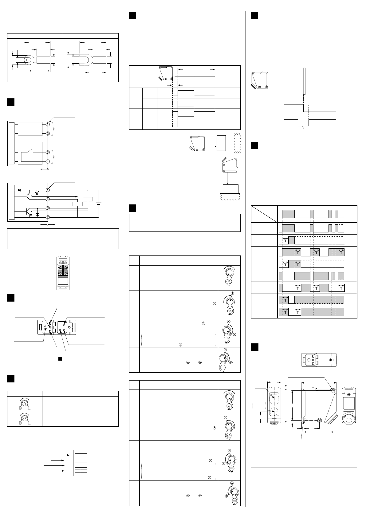
TIMER FUNCTION (EQ-5غT only)
٨
An OFF-delay timer, which is useful when the response of the connected device is slow, etc., an
ON-delay timer, which is useful when the input
specifications of the connected device require a signal of a fixed width, are possible with EQ-5غT.
٨
The OFF-delay timer and the ON-delay timer can be
used at the same time.
٨
For DC-voltage type, set the DIP switch for the timer
selecting to 'Timer ON' side.
Stable
operating
condition
Stable operating
condition
Unstable operating
condition
ON (lights up)
OFF (lights off)
Lights up
Lights off
<Time chart>
Sensing
condition
Operation
Light-received
normal operation
Light-received
ON-delay
Light-received
OFF-delay
Light-received
ON/OFF-delay
Light-interrupted
normal operation
Light-interrupted
ON-delay
Light-interrupted
OFF-delay
Light-interrupted
ON/OFF-delay
Note: Turn the timer switch gradually and lightly with the attach-
ed screwdriver. If the distance adjuster is over turned or
pressed heavily, it may be damaged.
13
DIMENSIONS (Unit: mm)
Beamreceiving
26
part
Beamemitting
part
Center of
sensing
22
3-M5 nut seats
(on both sides)
SUNX Limited
Timer period: T = 0.1 to 5s (variable)
3-Ǿ5.1 mounting hole
2
68
58
5 30
5
68
58
http://www.sunx.co.jp/
Beamreceived
Beaminterrupted
ON
OFF
ON
OFF
ON
OFF
ON
OFF
ON
OFF
ON
OFF
ON
OFF
ON
OFF
Head Office
2431-1 Ushiyama-cho, Kasugai-shi, Aichi, 486-0901,
Japan
Phone: +81-(0)568-33-7211 FAX: +81-(0)568-33-2631
Overseas Sales Dept.
Phone: +81-(0)568-33-7861 FAX: +81-(0)568-33-8591
PRINTED IN JAPAN
 Loading...