

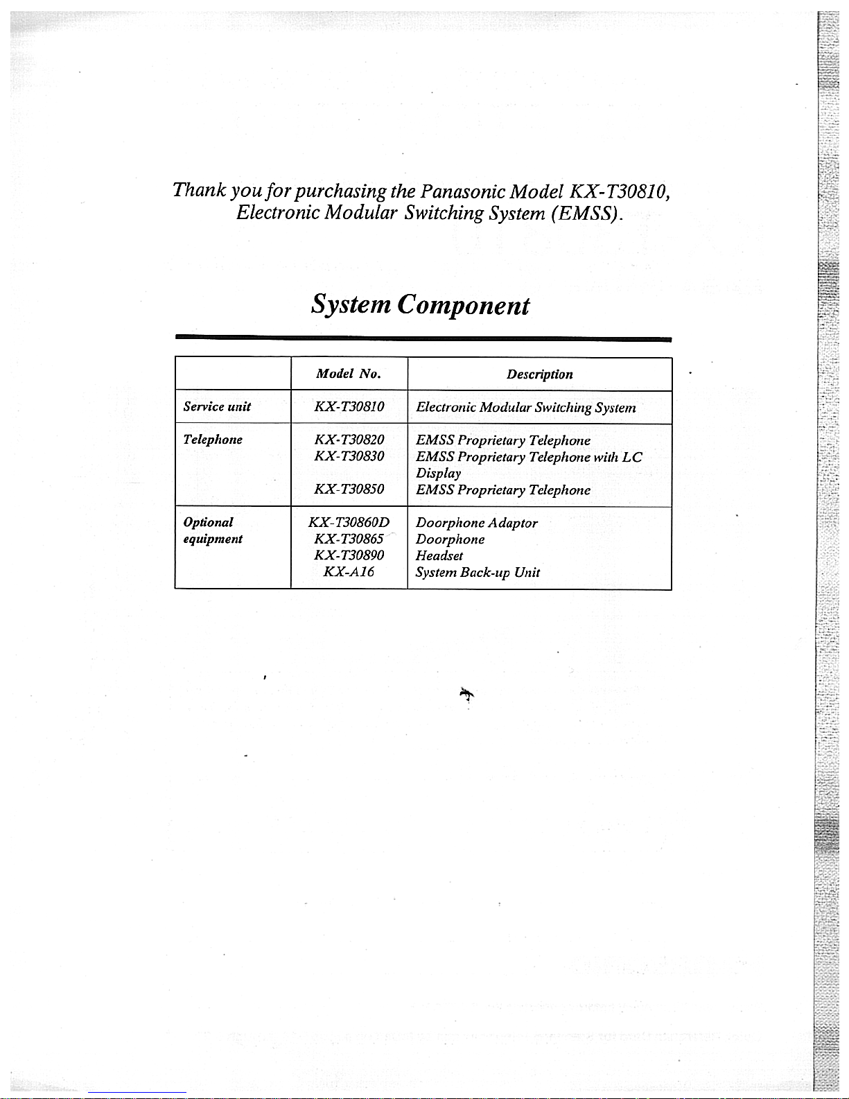
Panasonic EASA-PHONE KX-T30810 Installation Manual
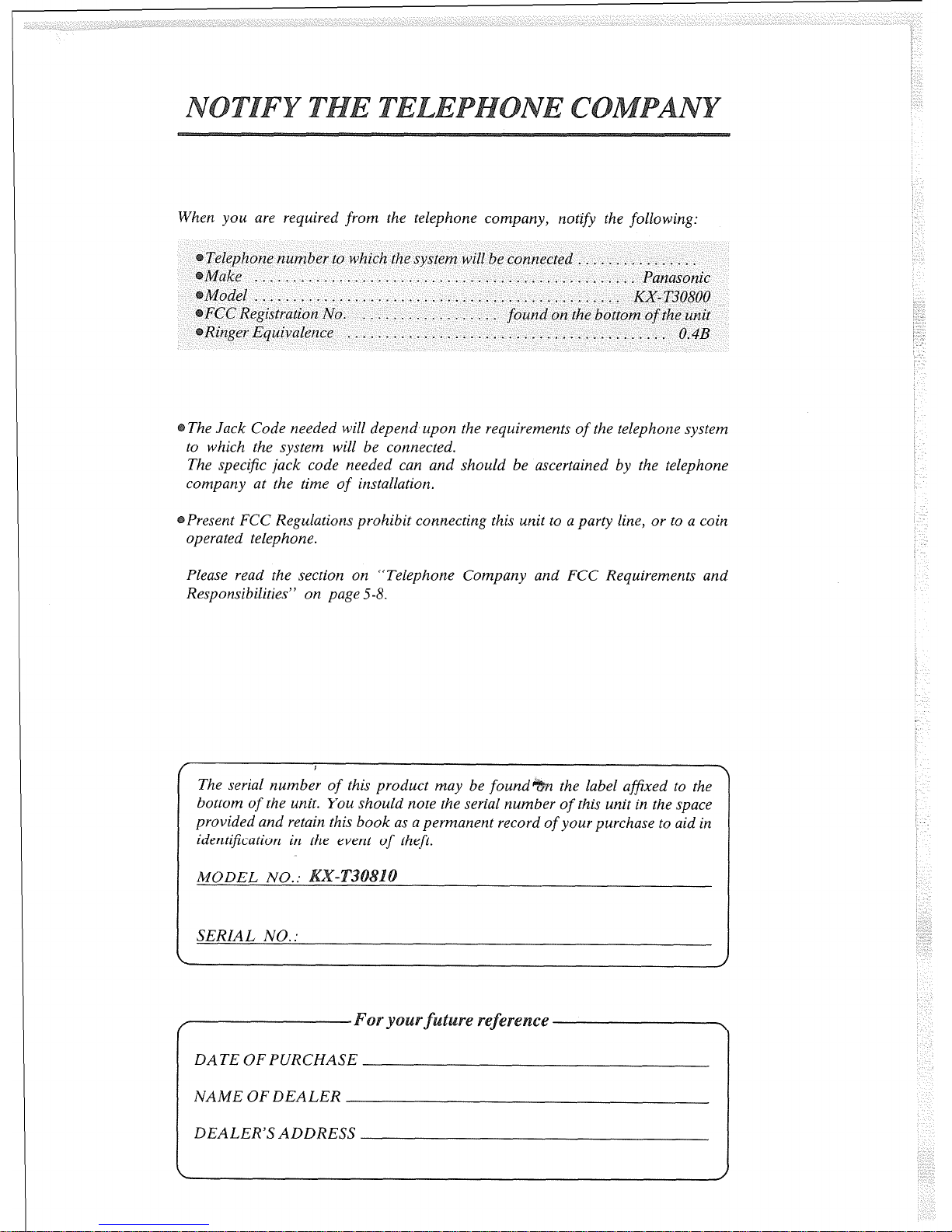
When you are required
from
the telephone company, notify
the
following:
Telephone number to which the system will be connected ................
Make .................................................. Panasonic
Model.. .............................................. KX-T30800
FCC Registration No. ..................
found
on the bottom
of the unit
Ringer Equivalence
.......................................... 0.43
The Jack Code needed will depend upon the requirements
of
the telephone system
to which the system will be connected.
The specific jack code needed can and should be ascertained by the telephone
company at the time
of
installation.
Present FCC Regulations prohibit connecting this unit to a party line, or to a coin
operated telephone.
Please read the section on “Telephone Company and FCC Requirements and
Responsibilities” on page 5-8.
f
I
\
The serial number of this product may be found
the label afixed to the
bottom
of
the unit. You should note the serial number
of
this unit in the space
provided and retain this book as a permanent record
of
your purchase to aid in
identification in the event
of theft.
MODEL NO.:
10
I
SERIAL NO. :
I
:
:
/ \
DATE OF PURCHASE
NAME OF DEALER
DEALER’S ADDRESS
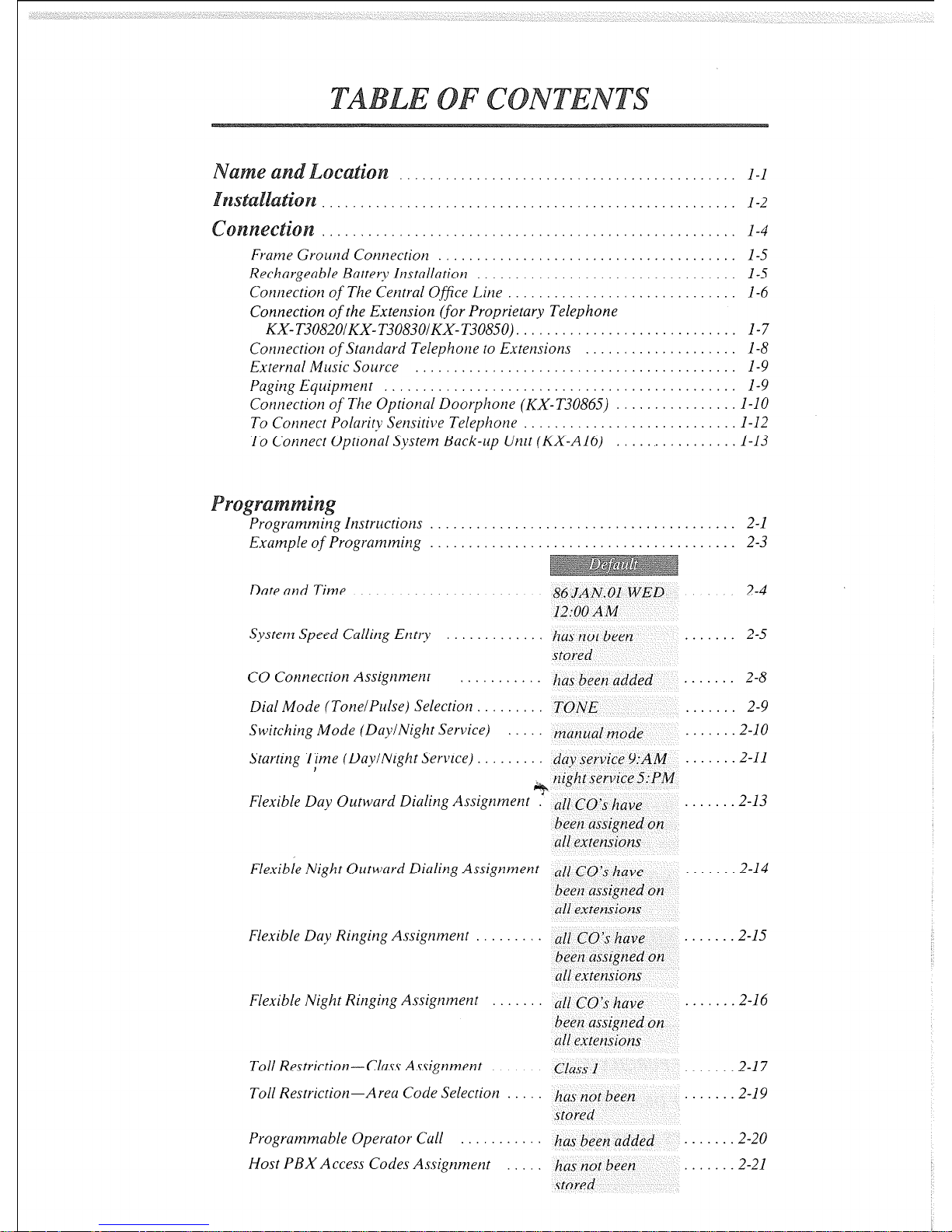
Frume Grourzd Connection
Rechargeable Battery Instullntion
Connecrion of The Central Office Line
Connection of the Extension (for Proprietary Telephone
KX- T3082O/KX- T3083OlKX- T308.50). . . . .
Connection of Standard Telephone to Extensions
External Music Source
Paging Equipment
Connection of The Optional Doorphone (KX-T30865)
To Connect Polarity Sensitive Telephone
To Connect Optional System Back-up Utlit (KX-A16)
Programming Instructions . . . . ...................... . . . 2-l
Example of Progratnming . . . . ...................... . . . 2-3
Date and Time .
86 JAN.01 WED
12:00 AM
2-4
System Speed Calling Entry
CO Connection Assignmenr
Dial Mode (TonelPulse) Selection . .
Switching Mode (DaylNight Service)
Starting 7;ime (DaylNight Service)
has not been
stored
.
2-5
has been added .
TONE
mattual mode
day service 9:AM
~ night service 5:PM
. . .
I . . . .
1 . . . .
. . .
. .
.
2-8
2-9
2-10
2-11
Flexible Duy Outward Dialing Assignment .’ all ~0’~ have
been assigned on
all extensions
2-13
Flexible Night Outward Dialing Assignment al[ ~0’s have
been assigned on
all extensions
2-14
Flexible Duy Ringing Assigntnent . all ~0’~ have
been assigned on
all extensions
. . . . . 2-15
Flexible Night Ringing Assigntnent all ~0’~ have
been assigned on
all exrensions
. . . . . I 2-16
Toll Restriction-Cluss Assignment cllIss 1 . . . . . . 2-17
Toll Restriction-Arerz Code Selection has not been
stored
Programmuble Operator Cull has been added
Host PBX Access Codes Assignment has tlot been
stored
. . , . 2-l 9
. . . 2-20
. . . . . .2-21
l-l
l-2
. 1-4
. l-5
. l-5
. l-6
. . . l-7
l-8
l-9
. l-9
l-10
1-12
1-13
2-22
Automatic Answering (AutomaticlManual)
Auto Answer
. . . . . .
Selection
Preferred Line Assignment.
.............. non-assignment ...
Programmable Call Waiting
............. has been removed ...
Duration Time Count Start Mode
......... 5S
after &al ...
Hookswitch Flash Timing ...............
600 msec ...
Disconnect Time .......................
1.5 see ...
Calling Party Control (CPC) Signal ....... has been added
...
Intercom Alerting Mode
.................
Tone Call ...
Programmable Doorphone .............
D-Phone 1,2 ...
Dial Call Pickup Group Assignment.
......
Pickup-G: 1 ...
Busy Tone Selection ...................
TONE: 1 ...
Hold Time Reminder ................... 3 minutes
...
Hold Recall Time Set ...................
30 set
...
Programmable External Paging Access Tone has been added
...
Programmable Toll Prefix
............... with 1
...
Programmable Secret Auto Dial .........
No Secret
...
. .
2-23
. . . 2-24
. . 2-25
. .
2-26
. . 2-27
. . 2-28
. 2-29
. .
2-30
. . 2-31
. 2-32
. . 2-33
. . 2-34
. 2-35
. . . 2-36
. . 2-37
Inter Oftice Calling (Intercom)
..................................
3-l
Outward Dialing.
.............................................
3-2
Speed Dialing
................................................
3-3
One Touch Dialing.
...........................................
3-4
Calling Doorphone.
...........................................
3-6
Distinctive Dial Tone
..........................................
3-6
Automatic Call Back Busy-(Camp-on) ...... : ...............
Busy Station Signaling ..................................
LastNumberRedial
......................................
Answer. .................
Automatic Answer-Intercom
Dial Call Pickup ..........
Directed Call Pickup ......
Call Park Retrieve ........
Doorphone ..............
Distinctive Ring Tone ......
ile
&?.a
Call on Hold-CO
Call on Exclusive Hold:Cg . 1 : 1: 1: 1: : 1
Call on Hold-Intercom , . . . . . . . . .
Call on Exclusive Hold-Intercom . . . . .
Conference . . . . . . . . . . . . . . .
Call Waiting. . . . . . . , . . . . . .
Call Transfer . . . . . . . . . . .
Call Splitting-Between CO and Intercom .
Call Splitting-Intercom . . . .
. . .
. . . .
. . .
......
......
......
......
......
......
3-7
3-8
3-8
3-9
3-9
3-10
3-10
3-11
3-12
3-12
........................
3-13
........................ 3-14
........................ 3-15
........................ 3-16
....................... 3-17
....................... 3-18
....................... 3-19
.......................
3-20
.......................
3-21
aging
Paging All Extensions
..............
Paging Group
......................
Paging-External ..................
Paging And Transfer ................
Paging-Answer ....................
use of
er Features
Background Music ..................
Mute Operation ....................
One Touch Access for System Features
External Feature Access
..............
PulselTone Conversion
..............
Time Setting. .......................
Intercom Alerting Mode. .............
Busy Lamp Field. ...................
Duration Time of Call Display
........
Lockout
..........................
Mixed Station Dialing ................
Power Failure Transfer
..............
tati0
g
Call Forwarding . .
Dial Call Pickup Deny
Do not Disturb . . .
Data Line Security
Saved Number Redial
Flexible Night Service
Station Program Clear
I
...... .._ ......
...............
...............
.
.
When a Line is Busy
....................
To Receive Calls ........................
While Having a Conversation. .............
Paging .................................
Use of Ofher Features ....................
Station Programming
.................
During Installation ......................
During Connection
......................
During Operation
......................
Reset Button
............................
D TMF Receiver Check ..................
. .
. . . .
. .
I .
. .
. .
. .
3-21
: 3-22
3-22
.3-23
.3-23
3-24
: 3-25
3-2.5
: 3-26
.3-27
.3-27
.3-28
3-28
: 3-29
3-29
: 3-29
3-29
..........
3-30
..........
3-32
..........
3-33
.......... 3-34
.......... 3-34
.......... 3-35
.......... 3-36
....... 4-l
....... 4-2
.......
4-3
....... 4-4
....... 4-5
.......
4-6
.......
4-8
5-l
5-2
5-3
5-3
. 5-4
Table of System Features
...................................... 5-5
List of Tones.
...................................................
5-6
ing Tones . . . . . . . . .
Specification
. . . . . . .
5-7
Telephone Company and FCC
esponsibilities
. . . . . . . . .
5-8
thers ..,_.......___............................................
5-9
rranty . . . . . . . . . . . . . . . . . . . . . . . . . . . . . . . . . . . . . . . . . . . . . . . . . . . . . .
..~-IO
...............................................
5-11
irectory .................................
.,.5-l 2
ming
Table
.........................................
.5-14
ference Card for
lephone ........... .5-18
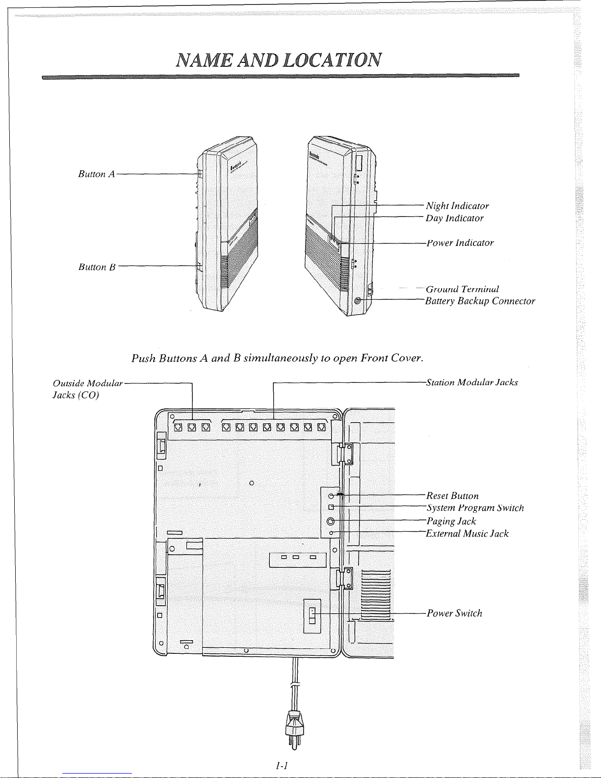
Button A
Button B
Power Indicator
round Terminal
attery Backup Connector
Push Buttons A and B simultaneously to open Front Cover.
Outside Modular __
Jacks (CO)
)Station Modular Jacks
tern Program Switch
II --
Power Switch
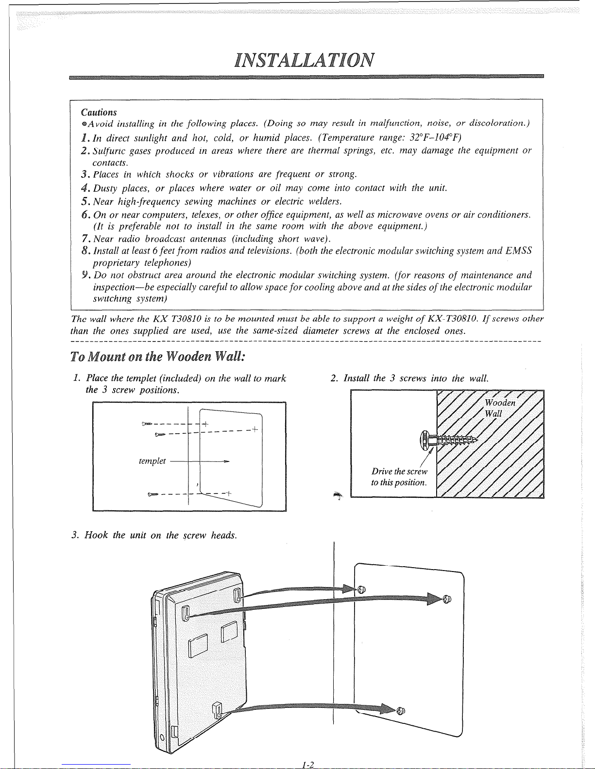
Avoid installing in the following places. (Doing so may result in malfunction, noise, or discoloration.)
. In direct sunlight and hot, cold, or humid places. (Temperature range: 32”F-104°F)
~ Sulfuric gases produced in areas where there are thermal springs, etc. may damage the equipment or
contacts.
. Piaces in which shocks or vibrations are frequent or strong.
.
Dusty places, or places where water or oil may come into contact with the unit.
5. Near high-frequency sewing machines or electric welders.
. On or near computers, telexes, or other office equipment, as well as microwave ovens or air conditioners.
(It is preferable not to install in the same room with the above equipment.)
.
Near radio broadcast antennas (including short wave).
s Install at least 6 feet from radios and televisions. (both the electronic modular switching system and EMSS
proprietary telephones)
. Do not obstruct area around the electronic modular switching system. (for reasons
of
maintenance and
inspection-be especially careful to allow space
for
cooling above and at the sides
of
the electronic modular
switching system)
The wall where the KY-T30810 is to be mounted must be able to support a weight
of
KX-T30810.
If
screws other
than the ones supplied are used, use the same-sized diameter screws at the enclosed ones.
1. Place the templet (included) on the wall to mark 2. Install the 3 screws into the wall.
-
the 3 screw positions.
zEs.------
-t-
~--- -.--------t-
templet
__
,
Qae------ ---+
ok the unit on the screw heads.
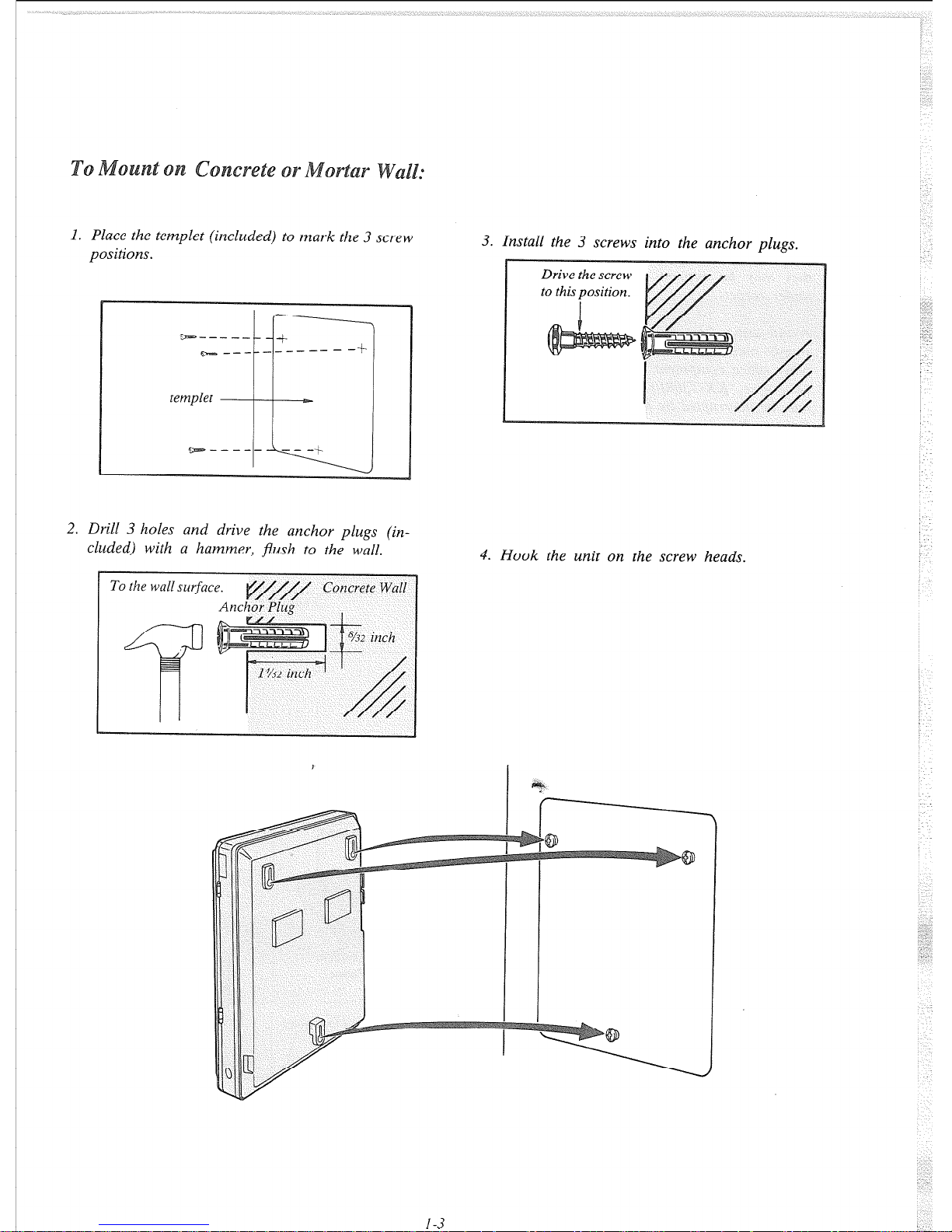
1. Place the templet (included) to mark the 3 screw
positions.
r
\
ycm ..--...._....-_ +
w _____ -------Jr
templet
3. Install the 3 screws into the anchor plugs.
4. Hook the unit on the screw heads.
2. Drill 3 holes and drive the anchor plugs (included) with a hammer, flush to the wall.
1-3
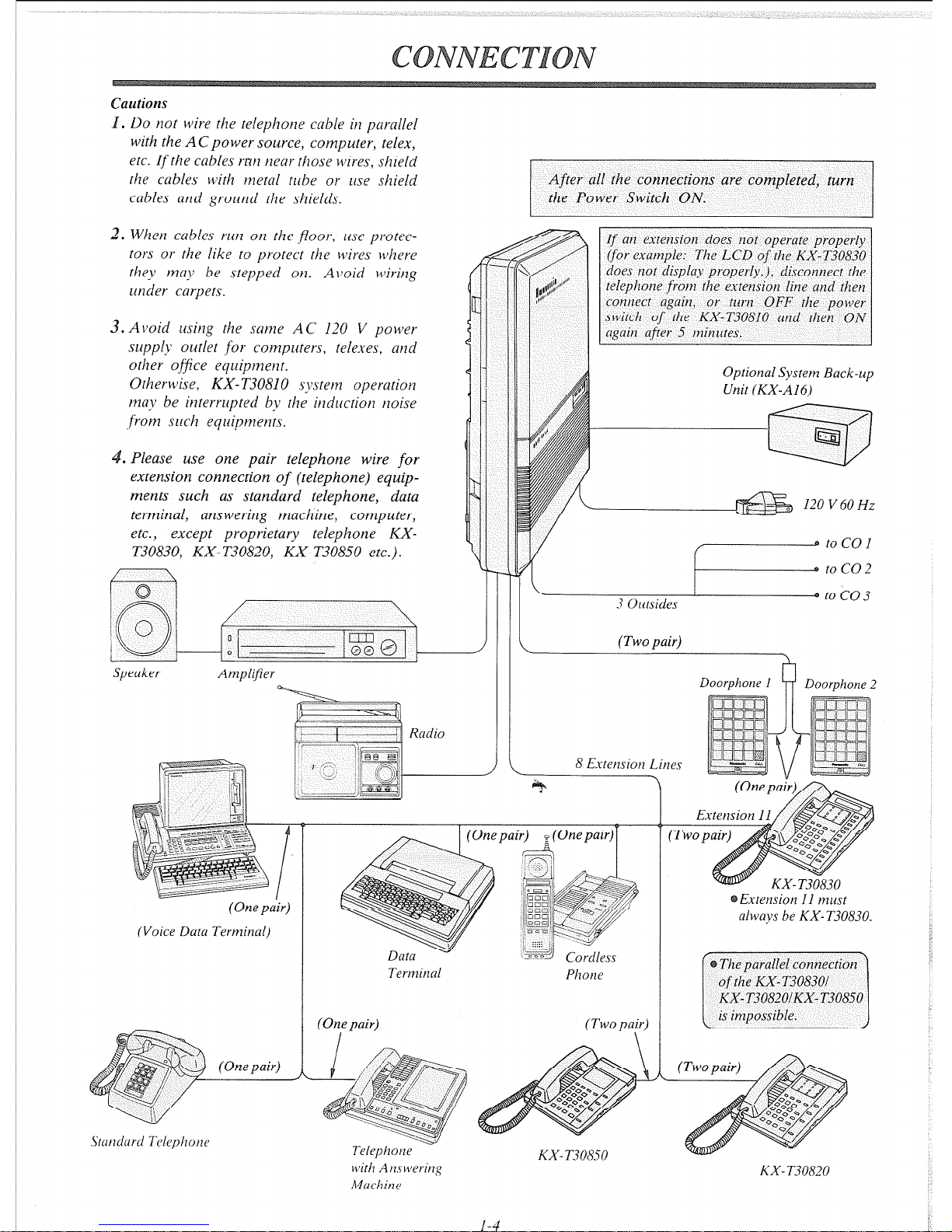
Cautions
. Do not wire the telephone cable in parallel
with the ACpower source, computer, telex,
etc. If the cables rrtn near those wires, shield
the cables with metal tube or use shield
cables atld ground the shields.
2. When cables ruu on the ,fZoorv use prorectars or the like to protect rhe wires where
rhey may be stepped on. Avoid wiring
under carpers.
3. Avoid using the same AC 120 V powel
supply outlet for compurers, telexes, and
ofher office equipment.
Otherwise, KX-T30810 system operation
may be inrerrupred by rhe irlducrion noise
.from such equipments.
. Please use one pair telephone wire for
extension connection of (telephone) equipments such as standard telephone, data
terminal, answering machine, computer,
etc., except proprietary telephone KX-
T30830, KX- T30820, KX-T30850 etc.).
Speaker
Anzplifier
(One pair)
(Voice Data Terminal)
After all rhe connechons are completed, turn
the Power Switch ON.
Optional Systenz Back-up
Unit (KX-AI6)
120 V 60 Hz
w
.a toC01
0 toco2
\I* to co 3
3 Omides
(Two pair)
8 Extemion Litles
Terminal
Phone
(Two pair)
\
Telephorle
with Arxwering
Machine
KX- T30850
1-4
Doorphone I Doorphone Z
Extension I1 must
always be KX- T30830.
KX- T30820
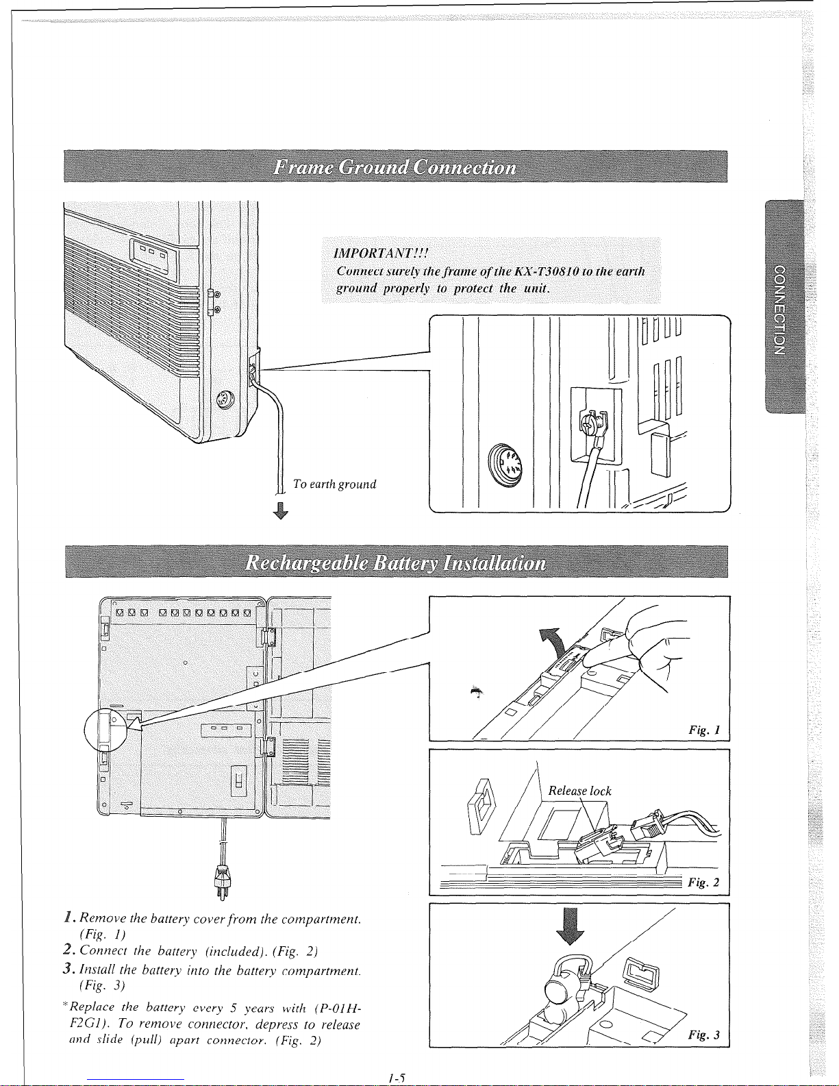
IMPORTANT!!!
Connect sure& the frame of the KX-T30810 to the earth
ground properly to protect the unit.
-
II
To
earth ground
I
( Fig.
2
. Remove the buttery cover from the compartment.
(Fig. I)
2. Corznect the battery (included). (Fig. 2)
3. Install the battery into the battery compartment.
(Fig. 3)
“Replace the battery every 5 years with
(P-01 H-
F2Gl). To remove connector, depress to release
and slide (pull) mpmrt com~ector. (Fig. 2)
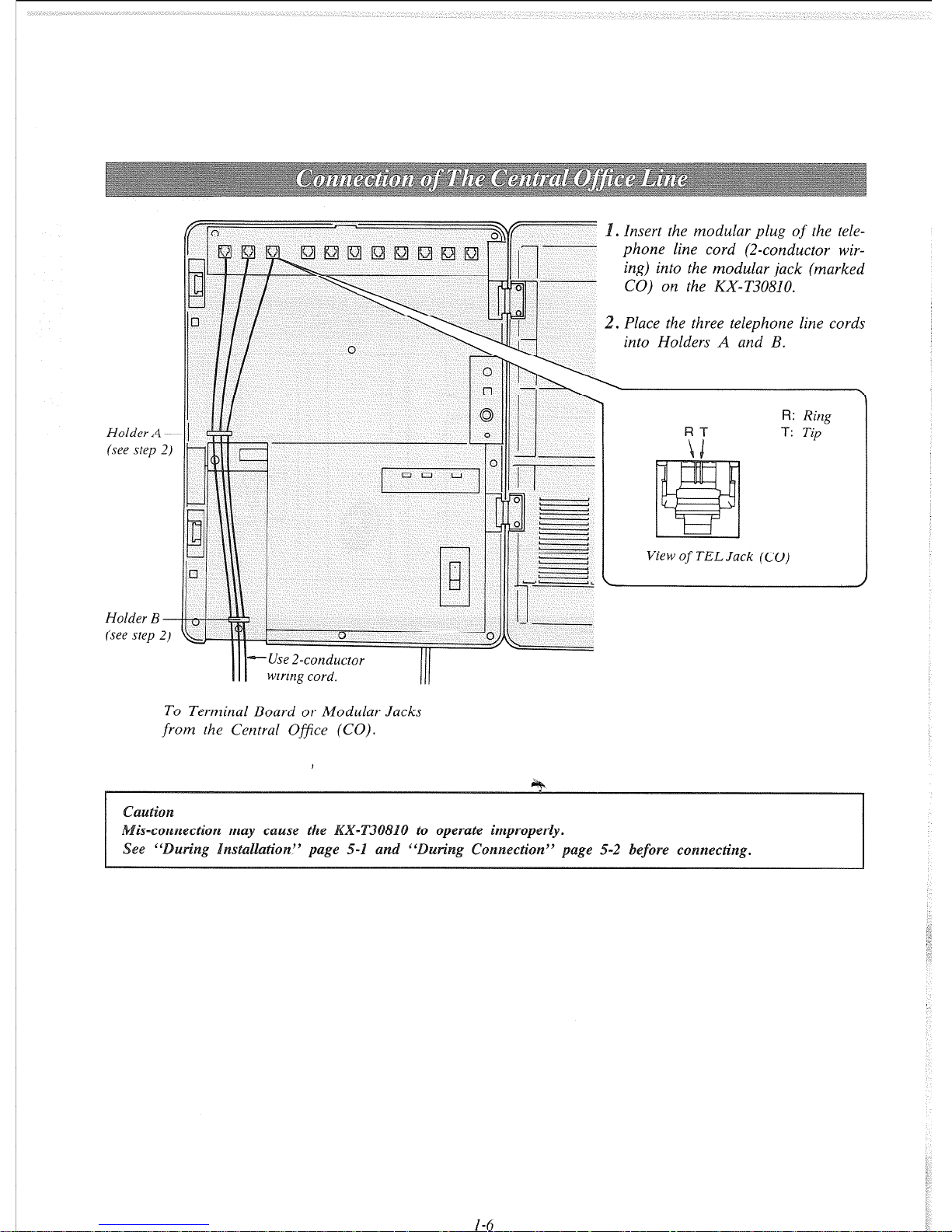
Holder A (see step 2)
Holder B (see step 2)
s
Insert
the modular
plug
of
the tele-
phone line cord (2-conductor wir-
ing) into the modular jack (marked
CO) on the KX-T30810.
2. Place the three telephone line cords
into Holders A and B.
1
I
I - I
I
-
-
View
of
TEL Jack (CO)
R: Rim I
T: T&” 1
III
+-Use 2-conductor
wiring cord.
To Terminal Board or Modular Jacks
from the Central Office (CO).
4htiO~
is-~o~~ec~o~ may cause the
operate i~~~o~e~ly.
See “
wing Installation” page 5-1 and ”
un’ng Connection” page 5-2
before connecting.
I-6
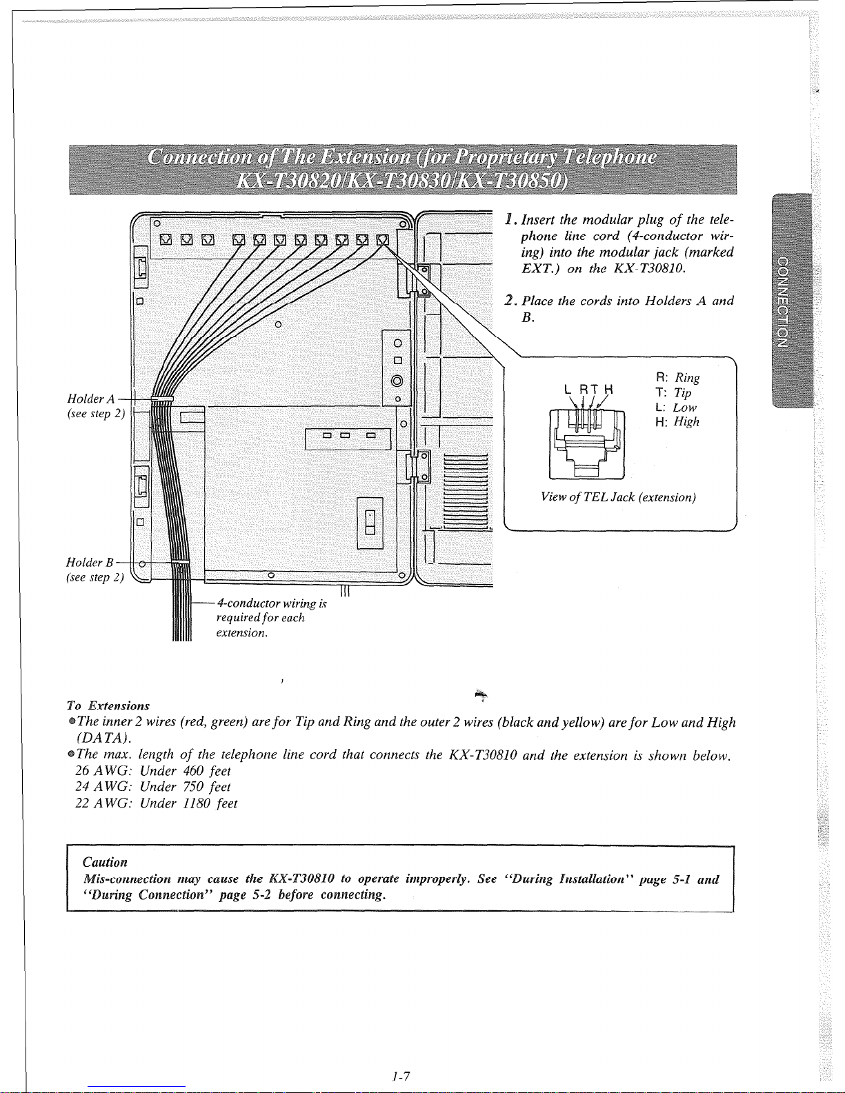
. Insert the modular plug of the tele-
phone line cord (4-conductor wir-
ing) into the modular jack (marked
EXT.) on the KX- T30810.
. Place the cords into Holders A and
View
of
TEL Jack (extension)
L:
LOW
H:
High
4-conductor wiring is
required for each
extension.
,
To &tensions
.
The inner 2 wires (red, green) are for Tip and Ring and the outer 2 wires (black and yellow) are for Low and High
(DA TA) .
The max. length of the telephone line cord that connects the KX-T30810 and the extension is shown below.
26 AWG: Under 460 feet
24 A WC: Under 750 feet
22 A WG: Under 1180 feet
is-connection m erate improperly. See “During Installation” page 5-1
and
1-7
Holder A
(see step
2)-
Holder B
(see step 2)-
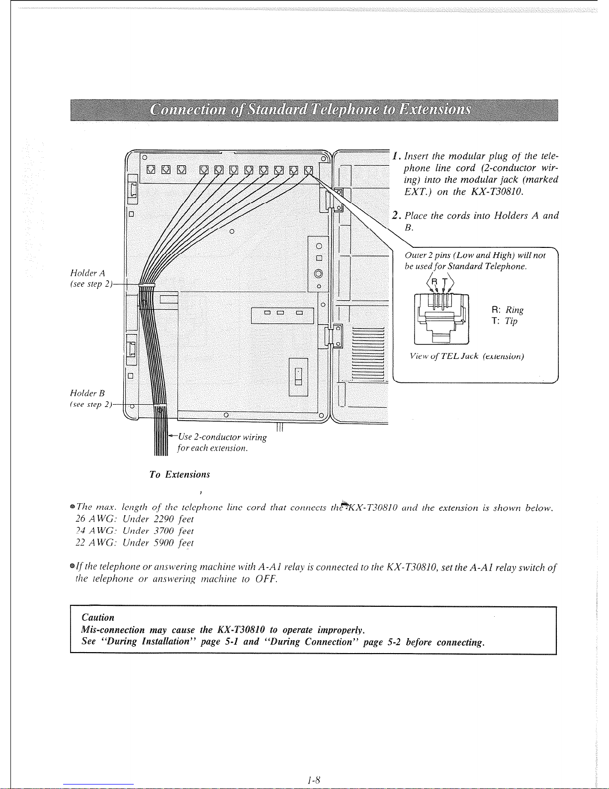
Insert rhe modular plug of the tele-
phone line cord (2-conductor wir-
ing) into the modular jack (marked
EXT.) on the KX-T30810.
Place rhe cords into Holders A and
Outer 2 pins (Low and High) will not
be used
for
Standard Telephone.
R: Ring
T:
Tip
View
of
TEL Jack (extension)
--Use 2-conductor wiring
for each extension.
To Extensions
The max. length of‘ rhe telephone line cord that cotltlects the*KX-T30810 atld rhe extension is shown below.
26 AWG: Utlder 2290 feet
24 AWG: Under 3700 feet
22 A WG: Under 5900 feet
[f rhe relephotle or atuwerhg machine with A-Al relay is cotlnected to rhe KX-T30810, set the A-Al relay switch of
rhe telephotle or atuwering tnuchine to OFF.
nection may cause the KAY-T30810 to operate improperly.
See ‘During Installation” page 5-1 and “During Connection” page 5-2 before connecting.
1-N
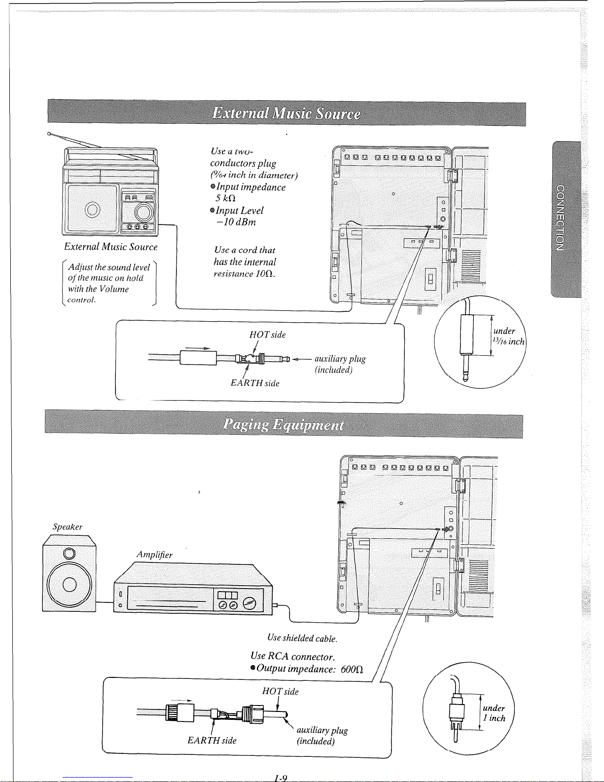
External Music Source
I
Adjust the sound level
of
the music on hold
with the Volume
I
I
control.
J t
Use a two-
conductors plug
(%4
inch in diameter)
Input impedance
5kR
Input Level
-10 dBm
Use a cord that
has the internal
resistance 1On.
HOTside
+--- auxiliary plug
(included)
EA’R TN side
Speaker
Use shielded cable.
Use RCA connector.
Output impedance: 6000
HOTside
EARTH side
auxiliary plug
(included)
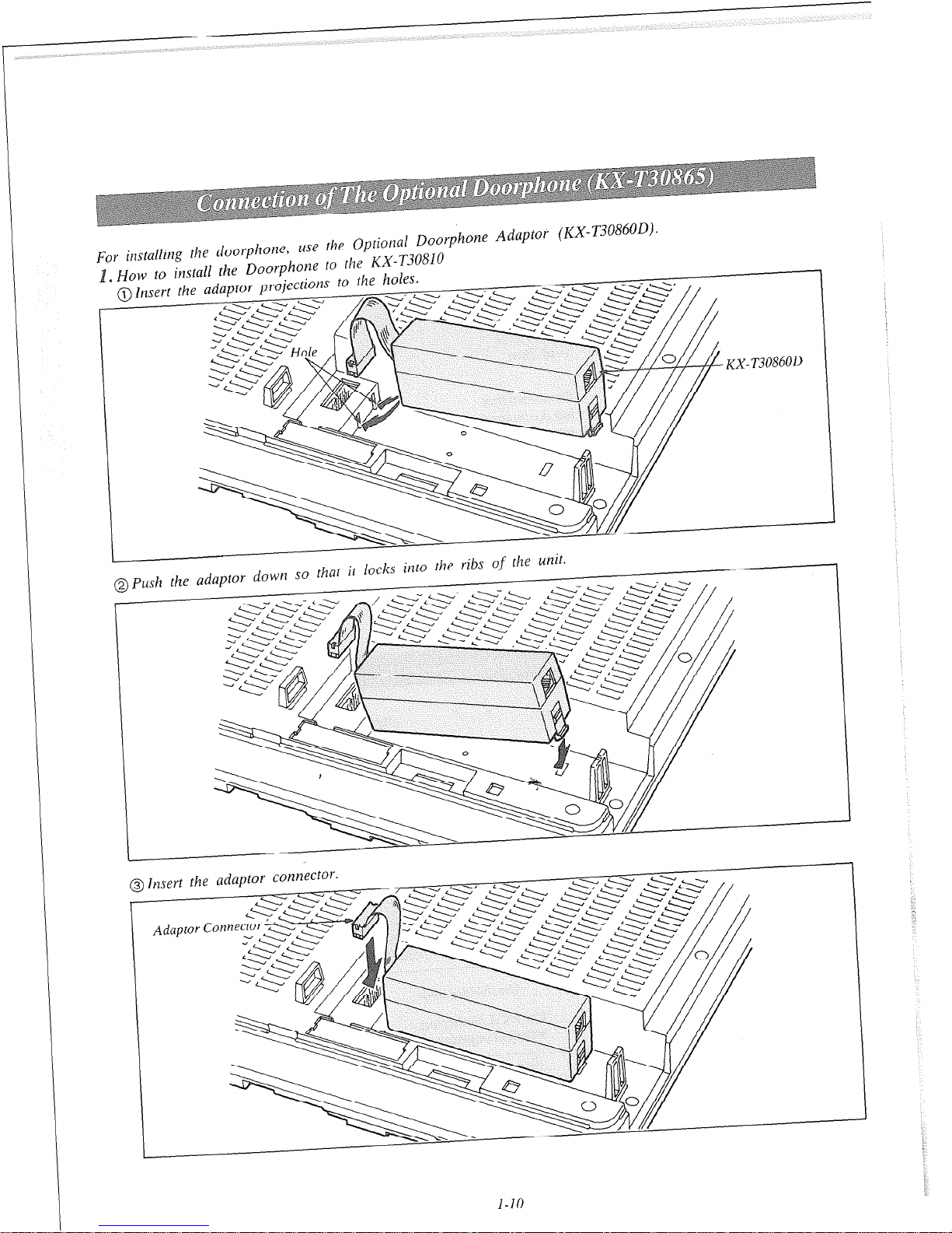
For installing the doorphone,
uSe the Optional Doorphone Adaptor (KX-ljudovu/.
~ HOW to install the Doorphone to the RX-T3 ^
-..,;nr+;nnr +n
the holes
- _
0810
/
I
the unit.
@push
the adaptor down so that it Locks
into
the ribs
-
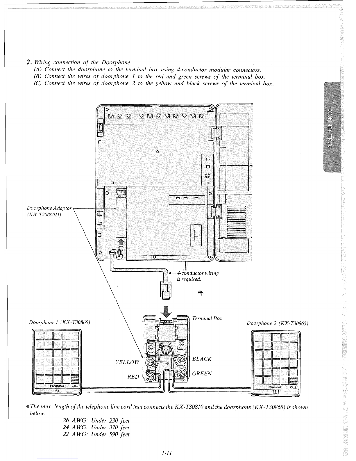
2. Wiring connection
of
the Doorphone
(A) Connect the doorphone to the terminal box using 4-conductor modular connectors.
(B) Connect the wires
of
doorphone 1 to the red and green screws
of
the terminal box.
(C) Connect the wires
of
doorphone 2 to the yellow and black screws
of
the terminal box.
Doorphone Adaptor
(KX-T3086OD)
III
4-conductor wiring
is required.
Doorphone 1 (KX-T30865)
The max. length
of
the telephone line
cord
that connects the KX-T30810 and the doorphone (KX-T30865) is shown
below.
26 A WG: Under 230
feet
24 A WC: Under 370
feet
22 A WG: Under 590
feet
I-11
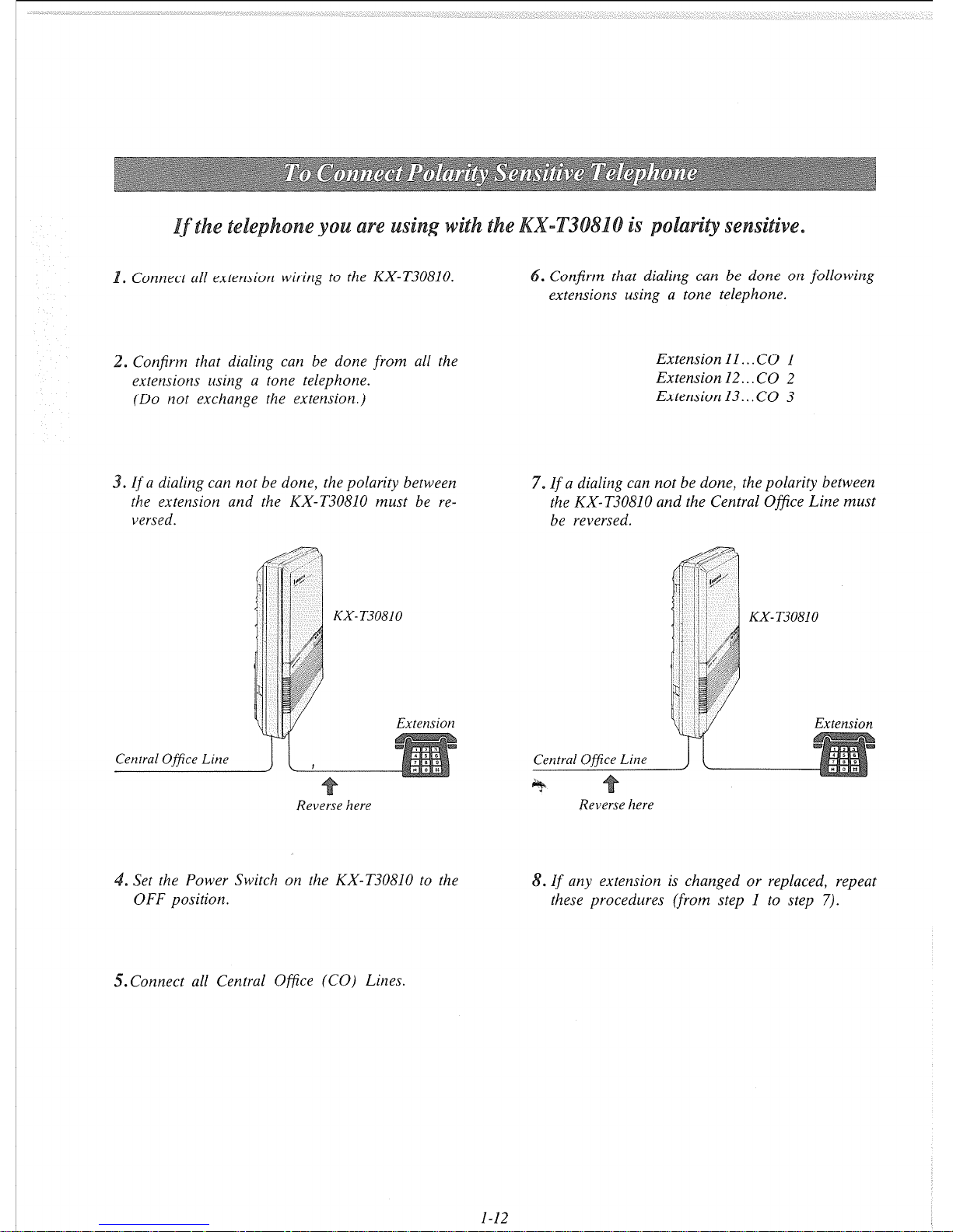
. Connect all extension wiring to the KX-T30810. . Confirm that dialing can be done on following
extensions using a tone telephone.
. Confirm that dialing can be done from all the
extensions using a tone telephone.
(Do not exchange the extension.)
Extension 11.. . CO 1
Extension 12.. CO 2
Extension 13...CO 3
.
if
a dialing can not be done, the polarity between
the extension and the KX-T30810 must be reversed.
Reverse here
7.
If
a dialing can not be done, the polarity between
the KX-T30810 and the Central Ofice Line must
be reversed.
Reverse here
. Set the Power Switch on the KX-T30810 to the
8.
If
any extension is changed or replaced, repeat
OFF position.
these procedures (from step 1 to step 7).
5.Connect all Central Office (CO) Lines.
l-12
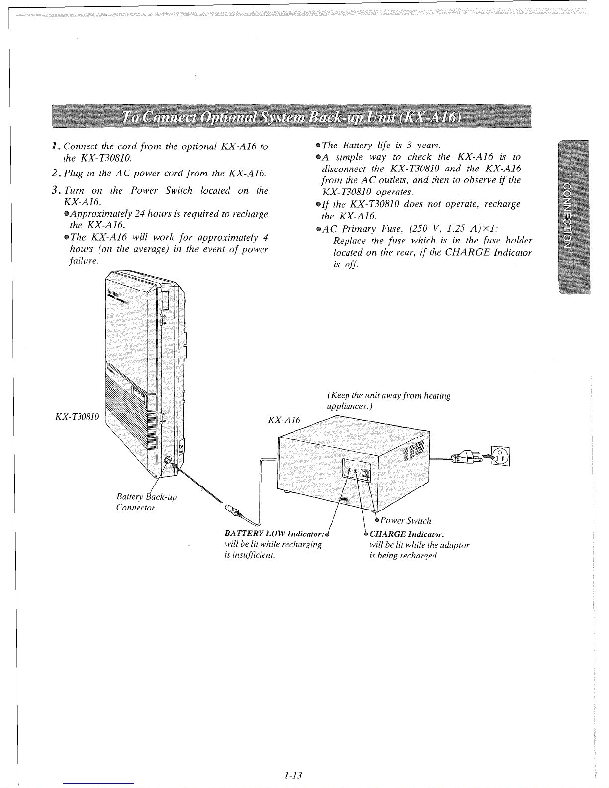
s
Connect the cord from the optional KX-A16 to
The Battery life is 3 years.
the KX- T30810.
A simple way to check the KX-A16 is to
Plug in the AC power cord from the KX-A16.
disconnect the KX-T30810 and the KX-A16
0
from the AC outlets, and then to observe if the
. Turn on the Power Switch located on the
KX-T30810 operates.
KX-A16.
Approximately 24 hours is required to recharge
the KX-A16.
The KX-A16 will work for approximately 4
hours (on the average) in the event of power
failure.
If the KX-T30810 does not operate, recharge
the KX-A16.
AC Primary Fuse, (250 V, 1.25 A) x I:
Replace the fuse which is in the fuse holder
located on the rear, if the CHARGE Indicator
is off.
KX-T30810
Battery B&k-up
Connector
(Keep the unit away
from
heating
appliances.)
BATTERY LOW Indicator:
will be lit while recharging
is insufj?cient.
Power Switch
CHARGE Indicator:
will be lit while the adaptor
is being recharged.
l-13
To activate this system, the requirements from telephone company and the customer must be programmed once the
Power Switch has been turned on.
. At extension 11:
All system programming changes (example: sys-
tem clear, station program clear, toll restriction,
hookswitch flash timing...) are done through
extensiorl 11,
. System Program Switch setting:
The System Program Switch located on the
KX-T30810 must be set to the PROGRAM
position while making program changes. After all
programming changes are completed, return the
program switch to the SET position.
3. Overlay:
This overlay is used for programming the system
and the program function names on buttons are
inscribed on this card. Refer to page 2-2.
. Before system programming, you may operate
systetn clear and station program clear to set
dqfault data of programming.
A. System Clear:
“SYSTEM CLEAR” will be displayed.
ess the NEXT button.
“ALL CLEAR?” will be displayed.
3 Press the MEMORY button to clear system.
4 To exit from system clear, press the END
button.
The following features are preset as the default
data.
Date and Time
System Speed Calling
CO Connection Assignment
Dial Mode (TonelPulse) Selection
Switching Mode (DaylNight Service)
Starting Time (DaylNight Sert1ic.e)
Flexible Day Outward Dialing Assignment
Flexible Night Outward Dialing Assignment
Flexible Day Ringing Assignment
Flexible Night Ringing Assignment
Toll Restrictiorz-C1as.r Assignment
Toll Restriction-Area Code Selection
Progrummable Operator Cull
Host PBX Access Codes Assignment
Automutic Answering (AutomaticlManuul)
Preferred Line Assignment
Programmable Call Waiting
Duration Time Count Start Mode
Hookswitch Flash Timing
Disconnect Time
Calling Party Control (CPC) Signal
Intercom Alerting Mode
Programmable Doorphone
Dial Call Pickup Group Assignment
Busy Tone Selection
Hold Time Reminder
Hold Recall Time Set
Programmable External Paging Access Tone
DTMF Receiver
Programmable Toll PreJix
Programmable Secret Auto Dial
B. Station Program Clear:
1 Dial (98).
“EXT CLEAR” will be displayed.
2 Press the NEXT button.
“ALL CLEAR?” will be displayed.
3 Press the MEMORY button to clear the
system.
4 To exit from station clear, press the END
button.
The following features are preset as the
defuult data.
One Touch Dialing
Background Music
Cull Forwarding
Data Line Security
Dial Call Pickup Deny
Do not Disturb
Selection
2-1
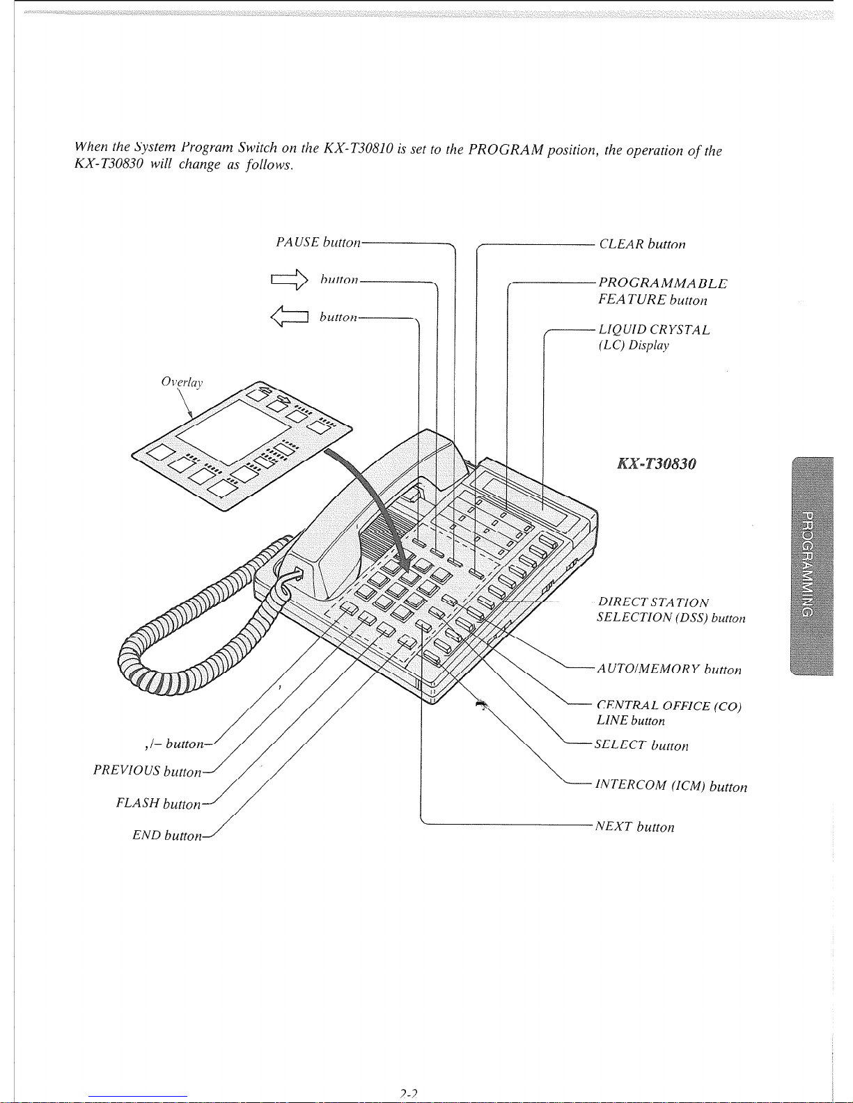
When the System Program Switch on the KX-T30810 is set to the PROGRAM position, the operation of
the
KX-T30830 will change as follows.
PR
PAUSE
button
,)
button
err?
button
-1
EVIOUS button
/
CLEAR button
PROGRAMMABLE
FEATURE button
/-.-----LIQUID CRYSTAL
(LC) Display
DIRECTSTATION
SELECTION (DSS) button
AUTOIMEMORY button
CENTRAL OFFICE (CO)
LINE
button
SELECT button
INTERCOM (ICM) button
END button
A NEXT button
2-2

n
Turn the Power Switch to ON
. . . . . . . . . . .
~ Set the System Program Switch to PROGRAM
. . . . . . . .
The LCD on the KX-T30830 shows “ENTER
PGM CODE”.
Be sure the handset
of
the extension 1’1 is in the cradle and
the speakerphone button
of
the extension 11 is off.
*
To program automatic line access number 9 and the phone
number 987-654-3210 into memory location {speed dial
access) number 00. (Refer to page 2-5.)
Dial (00) or press the Dial (00) or press the
NEXT button. NEXT button.
*
Dial “9”.
I‘
-” button.
g ;;?&)87”.
@ Press
“-” button.
@ Dial “654”.
@ Press “-” button.
@ Dial “3210”.
Press
“-” button.
Press the MEMORY
T
I
ension II
she
Display
ISPEED
c~mmG
1
ENTER SPEED CODE
If
nothing is stored in
access code “OO”,
100: NOTSTORED 1
If
already stored the
automatic line access
number 9 and the
phone number
123-456-7890.
[ 00: -123-456-7890 ]
100:
-987-654-3210 1
00: -987-654-32.10
button.
To program a next
access coae,
press the NEXT
button.
To program a desired access code, press the
SELECT button and then dial the number.
1 7. ) Repeat step 4 to 6.
)
While programming
if
a mistake is made,
. Press the “END” button.
2. Start programming procedure from
the beginning.
You will hear the beeps after press the
MEMORY button.
The MEMORY indicator light goes on when
the MEMORY button is pressed, and then
Indicator light goes out when the NEXT
or
PREV button is pressed.
~ Return the System Program Switch to SET
To make program change, start from the beginning.
2-3
(______...._____._____.___.~...............~......._.____._______._._______.._.I_______
enter the year with 2 digits.
[86]: 1986 year
~‘..“..~“.......‘....~~.......~..‘....‘.~~.‘.~“.‘..“‘~~~‘.“’......’
until the desired month is
displayed
: . . . . . . . . . . . . . . . . . . ..-......_......_..___________________ enter the
day
with 2
digits
,......._______________.______.__________
until the desired day of the
week is displayed.
,.._____...____.__.___..__
enter the hour with 2 digits
:...-.........‘..
enter the minute with 2 digits
r.- until the desired AMIPM is
\ displayed
~OO]~~~~T~~~]IO]~~~~~~T]~~:~]~~]IOI~~E~~~T]~~~]~~]I~]I~][~][SELECT]~MEMORY][END]
[86 JAN. 01 WED 12:OO AM].
. .defmdt
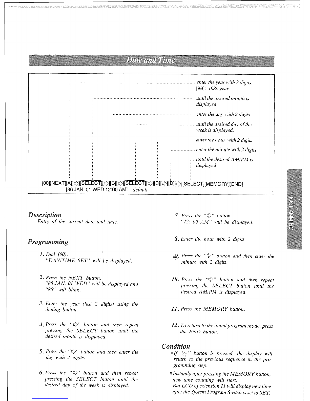
Dial (00).
,
*
“DAY/TIME SET” will be displayed.
2. Press the NEXT button.
“86 JAN. 01 WED” will be displayed and
“86” will blink.
3. Enter the year (last 2 digits) using the
dialing button.
~ Press the “0” b
utton
and then repeat
pressing the SELECT button until the
desired month is displayed.
5. Press the “0” button and then enter the
day with 2 digits.
. Press the “0’ button and then repeat
pressing the SELECT button until the
desired day of the week is displayed.
0
Press the “9” button and then enter the
’ minute with 2 digits.
. Press the “0” button and then repeat
pressing the SELECT button until the
desired AMIPM is displayed.
s
Press the MEMORY button.
. To return to the initial program mode, press
the END button.
button is pressed, the display will
return to the previous sequence in the pro-
gramming step.
Instantly after pressing the MEMORY button,
new time counting will start.
But LCD
of
extension 11 will display new time
after the System Program Switch is set to SET.
3-4
._........__._....____..__...._....._.__.__________.
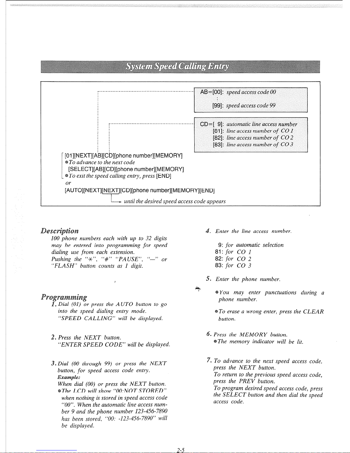
I][phone number][ME
To advance to the next code
[SELECT][AB][CD][phone number][MEMORY]
To exit the speed calling entry, press
[END]
~“TO]~~~XT]~~~~T]~~D]~phone
number][ME
L--- until the desired speed access code appears
100 phone numbers each with up to 32 digits
may be entered into programming for speed
dialing use from each extension.
Pushing the “-X-“, “#” “PAUSE”, “-” or
“FLASH” button counts as 1 digit.
.
Enter the line access number.
9:
for
automatic selection
81: for
CO 1
82:
for
CO 2
83:
for
CO 3
) or press the AUTO button to go
into the speed dialing entry mode.
“SPEED CALLING” will be displayed.
0
Enter the phone number.
You may enter punctuations during a
phone number.
To erase a wrong enter, press the CLEAR
button.
.
Press the NEXT button.
“ENTER SPEED CODE” will be displayed.
3. Dial (00 through 99) or press the NEXT
button,
for
speed access code entry.
n dial (00) or press the NEXT button.
e LCD will show “0O:NOT STORED”
when nothing is stored in speed access code
“00”. When the automatic line access number 9 and the phone number 123-456-7890
has been stored, “00: -123-456-7890” will
be displayed.
Press the MEMORY button.
The memory indicator will be lit.
7. To advance to the next speed access code,
press the NEXT button.
To return to the previous speed access code,
press the PREV button.
To program desired speed access code, press
the SELECT button and then dial the speed
access code.
2-5
8. Repeat steps 4 to 7.
. To exit the speed dial entry, press the END
utton.
The LCD will show the initial program
mode,
“ENTER PGM CODE”.
oc
e
Repeat steps 1 to 9.
the 13 digits of a phone number, use
‘, or ‘i@’ button for scrolling the
display.
The LCD will show the stored phone
number.
The line access number (9, 81, 82 or 83)
should be stored.
When dialing, the pause is automatically
entered after line access number (9, 81, 82,
or
83).
Continuous use of speed dialing is possible.
EXW?pl6C
[AUTO] [Ol] [AUTO] [02]
In this case, speed access code “02” should not
include the line access number.
. Dial (01) or press the AUTO button.
“SPEED CALLING” will be displayed.
2. Press the NEXT button.
“ENTER SPEED CODE” will be dis-
played.
3. Dial (00 through 99) or press the NEXT
button, for speed access code entry.
The speed access code and the phone number
will be displayed.
. Press the CLEAR button.
5. Press the MEMORY button.
.
To advance to the next speed access code,
press the NEXT button,
To return to the previous speed access code,
press the PREV button.
To program desired speed access code, press
the SELECT button and then dial the speed
access code.
7. Repeat steps 4 to 6.
There is the phone number directory on page
5-12.
.
To exit the speed dial entry, press the END
button.
2-6

1) To enter line access number 81 and telephone number 201-392-4669 into speed access code 00.
(OJ NEXT 00 81- 201-382-4669 MEMORY END)
77
Speed access j
Telephone
code
number
line access
number
If
punctuations do not enter during a phone number, LC Display will show as below.
(00: 812013924669)
2) To enter automatic line access number 9 and telephone number 201-392-4669 into speed access code 02.
Q-i NEXT 02 9- 201-392-4669 MEMORY END)
-i-I
: i
Speed access j
Telephone number
code
automatic line
access number
3)
To access MC1
(OJ [VEXT QJ 9-
123-4567 PAUSE PAUSE 9876 201-348-7000 MEMORY END)
t
Speed access 1
* :
Security Telephone
code I
I
MCI number
code number
automatic line
access number
PAUSE button
4)
To access ITT
(&l NEXT 92 8,’ 765-4321 PAUSE PAySE 201-348-7000 6_789 MEMORY END)
: I
Speed access ; ;
code
Security
I
,
Telephone code
I
ITTnumber j
number
I
Line access
number
PA LOSE button
When the dialing mode is required to change a pulse mode to a tone mode. (See page 3-27)
pulse mode
tone mode
I-..
-4
(01 NEXT 02 82-B X # PAUSE PAUSE 201-348-7000 6789 MEMORY END)
-T-T---
: :
; # button
* button
2-7
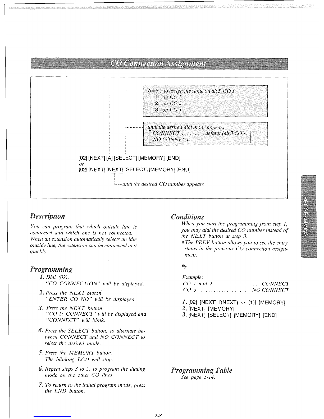
:-‘--------‘--‘--.---- A=-%: to assign thesame on a113 CO’s
T.-‘.‘--....
until the desired dial mode appears
i
CONNECT. . . . . . . . default (al13 CO’s)
NO CONNECT
[02] [NEXT] [ii] [SELECT] [MEMORY] [END]
;2] [NEXT] [NEXT] [SELECT] [MEMORY] [END]
L--until the desired CO number appears
s
You can program that which outside line is
connected and which one is not connected.
When an extension automatically selects an idle
outside line, the extension can be connected to it
quickly.
“CO CONNECTION” will be displayed.
. Press the NEXT button.
“ENTER CO NO” will be displayed.
3. Press the NEXT button.
“CO 1: CONNECT” will be displayed and
“CONNECT” will blink.
.
Press the SELECT button, to alternate between CONNECT and NO CONNECT to
select the desired mode.
. Press the MEMORY button.
The blinking LCD will stop.
. Repeat steps 3 to 5, to program the dialing
mode on the other CO lines.
7. To return to the initial program mode, press
the END button.
When you start the programming from step I,
you may dial the desired CO number instead of
the NEXT button at step 3.
The PREV button allows you to see the entry
status in the previous CO connection assignment.
Example:
CO 1 and 2 . . . CONNECT
CO 3 . . . . . . . . . . . . . . . . . . NOCONNECT
. [02] [NEXT] [(NEXT) or (l)] [
2. [NEXT] [MEMORY]
3. [NEXT] [SELECT] [MEMORY] [END]
e
See page 5-14.
3-R
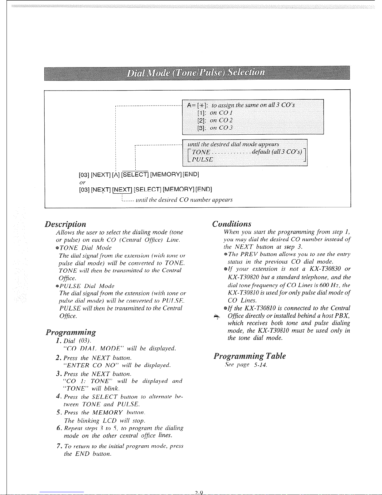
- A= [-%I: to assign the same on all 3 CO’s
until the desired dial mode appears
default (all 3 CO’s)
[03] [NEXT] [,4] [SELECT] [ME
;3] [NEFT] [NEXT] [SELECT] [MEMORY] [END]
1. _ _ _ _
until the desired CO number appears
S
Allows the user to select the dialing mode (tone
or pulse) on each CO (Central Office) Line.
TONE Dial Mode
The dial signal from the extension (with tone or
pulse dial mode) will be converted to TONE.
TONE will then be transmitted to the Central
Office.
PULSE Dial Mode
The dial signal from the extension (with tone or
pulse dial mode) will be converted to PULSE.
PULSE will then be transmitted to the Central
Of&e.
“CO DIAL MODE” will be displayed.
2. Press the NEXT button.
“ENTER CO NO” will be displayed.
3. Press the NEXT button.
“CO 1: TONE” will be displayed and
“TONE” will blink.
.
Press the SELECT button to alternate between TONE and PULSE.
5. Press the MEMORY button.
The blinking LCD will stop.
6. Repeat steps 3 to 5, to progrum the diuling
mode on the other central ojjice lines.
7. To return to the initial program mode, press
the END button.
2-Y
When you start the programming from step 1,
you muy dial the desired CO number instead of
the NEXT button at step 3.
The PREV button allows you to see the entry
status in the previous CO dial mode.
If
your extension is not a KX-T30830 or
KX-T30820 but a standard telephone, and the
dial tone frequency
of
CO Lines is 600 Hz, the
KX- T30810 is used
for
only pulse dial mode
of
CO Lines.
If the KX-T30810 is connected to the Central
Ofjcice directly or installed behind a host PBX,
which receives both tone and pulse dialing
mode, the KX-T30810 must be used only in
the tone dial mode.
e
See page 5-14.
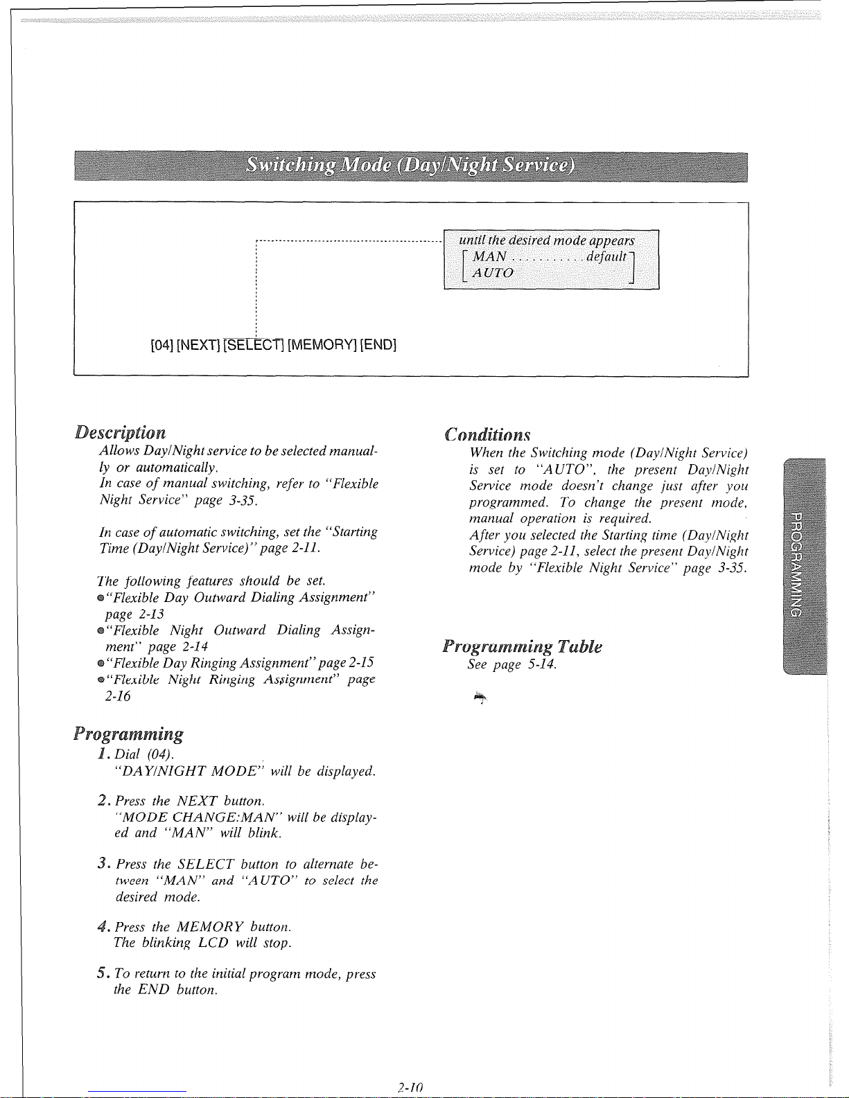
until the desired mode appears
-~I
[04] [NEXT] [SELkCT] [MEMORY] [END]
&SC
Allows DaylNight service to be selected manually or automatically.
In case of manual switching, refer to “Flexible
Night Service” page 3-35.
In case
of
automatic switching, set the “Starting
Time (DaylNight Service)” page 2-11.
The following features should be set.
“Flexible Day Outward Dialing Assignment”
page 2-13
“Flexible Night Outward Dialing Assign-
ment” page 2-14
“Flexible Day Ringing Assignment”page 2-15
“Flexible Night Ringing Assignment” page
2-16
“DAYINIGHT MODE” will be displayed.
* Press the NEXT button.
“MODE CHANGE:MAN” will be display-
ed and “MAN” will blink.
0
Press the SELECT button to alternate between “MAN” and “AUTO” to select the
desired mode.
.
Press the MEMORY button.
The blinking LCD will stop.
5. To return to the initial program mode, press
the END button.
s
When the Switching mode (Day/Night Service)
is set to “AUTO”,
the present DayiNight
Service mode doesn’t change just after you
programmed. To change the present mode,
manual operation is required.
After you selected the Starting time (DaylNight
Service) page 2-11, select the present DaylNight
mode by “Flexible Night Service” page 3-35.
See page 5-14.
2-10
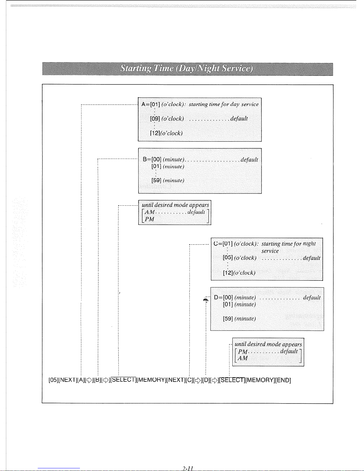
‘------------.-----.---‘---------- A=[Ol] (o’clock): starting timefor day service
[OS] (o’clock) . . . . . . . . , . . . . . default
[12](o’clock)
~------------.----“---. B=[OO] (minute). . . . . . . . . . . . . . . . . , default
[ql] (minute)
[is] (minute)
~________.~.
C=[Ol] (o’clock): starting time for night
1651 (o’clock)
service
. . . . . . . . . . . . . default
[ 121 (o’clock)
--- D=[OO] (minute) . . . . . . . . . . . . . . default
6
[Ol] (minute)
[59] (minute)
7-71
 Loading...