

Panasonic DVDLS-90-PP, DVDLS-93-P Service manual
ORDER NO.CHM0503005CE
Portable DVD/CD PLAYER
DVD-LS90PP
DVD-LS93P
RAE1905Z-2C Mechanism Series
Colour
(S).................Silver Type
B12
Specifications
Operating temperature
range: +5 to +35°C (+41 to +95°F)
Operating humidity range: 5-85% RH (no condensation)
Region number: Region No.1
Discs played
[8cm (3”) or 12cm (5”)]:
Signal system: NTSC
LCD screen: 9” -Si, TFT wide-screen LCD
Composite-video output:
DVD (DVD-Video)
DVD-RAM (DVD-VR, JPEG(*1, 5))
DVD-R (DVD-Video )
DVD-RW (DVD-Video, DVD-VR)
+R/RW (Video)
CD, CD-R/RW [CD-DA, Video -CD,
SVCD(*1), MP3(*2, 5), WMA(*3, 5),
JPEG (*4, 5), HighMAT Level 2
(Audio and Image)]
*1: Confo rming to IEC62107
*2: Compatible compression rate:
between 32 kbps and 320 kbps
*3: Compatible compression rate:
between 48 kbps and 320 kbps
*4: Exif Ver 2.1 JPEG Baseline files
Picture resolution: between 320×240
and 6144×4096 pixels (sub sampling
is 4:2:2 or 4:2:0)
*5: The total combined maximum
number of recognizalbe audio and
picture contents and groups: 4000
audio and picture contents and 400
groups.
© 2005 Matsushita Electric Industrial Co., Ltd. All
rights reserved. Unauthorized copyin g and
distribution is a violation of law.

A
V
V
A
DVD-LS90PP / DVD-LS93P
Output level: 1Vp-p (75Ω)
Output terminal: Mini-jack
Number of terminals: 1system
Audio output:
Output level: 1.5Vrms (1kHz, 0dB, 10kΩ )
Output terminal: Stereo mini-jack
Number of terminals: 1system
Audio performance:
(1) Frequency response:
lDVD (linear audio): 4Hz-22kHz (48kHz sampling)
4Hz-44kHz (96kHz sampling)
lCD audio: 4Hz-20kHz
(2) S/N ratio:
lCD audio: 115dB
(3) Dynamic range:
lDVD (linear audio): 98dB
lCD audio: 97dB
(4) Total harmonic distortion:
lCD audio: 0.008%
Digital audio output:
Optical digital outpu t: Mini optical terminal
Number of terminals: 1system
(also used for audio output)
Pickup:
Wave length: 662nm / 785nm (DVD/CD)
Laser power: CLASS 2/ CLASS 3A (DVD/CD)
Power supply: DC 12V (DC IN terminal) /
DC 7.2V (Exclusive battery terminal)
Power consumption
13W (Unit only: 10W)
(Using included AC adaptor):
Power consumption in
approx. 0.5W
Standby mode
(Using included AC adaptor):
Power consumption in
13W
Recharge mode
(Using included AC adaptor):
AC adaptor:
Power source:
C 100-240V, 50/60Hz
Power consumption: 28W
DC output: 12V, 1.5A
Battery pack CGR-H702
(lithium ion)(LS-90 included):
oltage: 7.2V
Capacity: 4700mAh
Battery pack CGR-H703
(lithium ion)(LS-93 included):
oltage: 7.2V
Capacity: 8600mAh
Dimensions (excluding
protrusions and battery):
DVD-LS90: 235.4(W) x 178.6 (D) x 39.0*(H) mm
9
[9
/32” (W) x 71/32” (D) x 117/32” (H)]
3
*29.9mm (1
[D=184.9mm (7
[H=51.4mm (2
/16”) at lowest point
9
/32”) including battery]
1
/32”) including battery]
DVD-LS93: 235.4(W) x 178.6 (D) x 39.0*(H) mm
9
/32” (W) x 71/32” (D) x 117/32” (H)]
[9
3
*29.9mm (1
[D=201.4mm (7
/16”) at lowest point
15
/16”) including
battery]
[H=51.5mm (2
1
/32”) including battery]
Mass (including battery):
DVD-LS90: 1097g (38.69 oz)
DVD-LS93: 1280g (45.15 oz)
solder:
This model uses lead free solder (PbF).
Note
Specifications are subject to change without notice.
Mass and dimensions are approximate.
Manufactured under license from Dolby Laboratories.
“Dolby“ and the double-D symbol are trademarks of Dolby
Laboratories.
“DTS“ and “DTS 2.0+ Digital Out” are trademarks of Digital Theater
Systems, Inc.
pparatus Claims of U.S. Patent Nos. 4,631 ,603, 4,577,216, and
4,819,098, licensed for limited viewing uses only.
This product incorporates copyright protection technology that is
protected by method claims of certain U.S. patents and other
intellectual property rights owned by Macrovision Corporation and
other rights owners. Use of this copyright protection technology
must be authorized by Macrovision Corporation , and is intended for
home and other limited viewing uses only unless otherwise
authorized by Macrovision Corporation. Reverse engineering or
disassembly is prohibited.
Windows Media, and the Windows logo are trademarks, or
registered trademarks of Microsoft Corporation in the United States
and/or other countries.
WMA is a compression format developed by Microsoft Corporation.
It achieves the same sound quality as MP3 with a file size that is
smaller than that of MP3.
MPEG Layer-3 audio decoding technology licensed from
Fraunhofer llS and Thomson multimedia.
HighMAT™ and the HighMAT logo are either trademarks or
registered trademarks of Microsoft Corporation in the United States
and/or other countries.
2

DVD-LS90PP / DVD-LS93P
CONTENTS
Page Page
1 SAFETY PRECAUTIONS 4
1.1. GENERAL GUIDELINES
2 PREVENTION OF ELECTRO STATIC DISCHARGE (ESD) TO
ELECTROSTATICALLY SENSITIVE (ES) DEVICES
3 PRECAUTION OF LASER DIODE
4 HOW TO REPLACE THE LITHIUM BATTERY
5 LITHIUM ION BATTERY
6 ABOUT LEAD FREE SOLDER (PbF)
7 HANDLING PRECAUTIONS FOR TRAVERSE DECK
7.1. Handling of optical pickup
7.2. Grounding for electrostatic breakdown prevention
8 DISASSEMBLY, REASSEMBLY AND SERVICE POSITION
8.1. Disassembly
8.2. P.C.B. location
8.3. Main cabinet of the unit
8.4. Traverse assembly
8.5. Optical pick-up unit
8.6. Disc motor
8.7. Main P.C.B.
8.8. Operation P.C.B.
8.9. Monitor assembly
8.10. Disc cover
8.11. Monitor cover
8.12. Mono arm
8.13. Inverter P.C.B.
8.14. LCD panel
8.15. Service position
9 SELF-DIAGNOSIS FUNCTION AND SERVICE MODE
9.1. Optical Pickup Breakdown Diagnosis
9.2. UHF displays
9.3. Service Mode Table 1
9.4. DVD Self Diagnostic Function-Error Code
9.5. Last Error Code saved during NO PLAY
9.6. Service mode table
9.7. Lens cleaning
10 SERVICE PRECAUTIONS
10.1. Recovery after the dvd player is repaired
10.2. Firmware version-up of the DVD player
11 ADJUSTMENT PROCEDURES
11.1. Service Tools and Equipment
11.2. Important points in adjustment
11.3. Storing and Handling Test Discs
11.4. Optical adjustment
11.5. Electrical adjustment (LCD)
11.6. Electrical check (Video output check)
10
10
11
12
12
13
13
13
14
14
15
16
16
17
18
18
19
20
20
21
22
23
24
24
24
25
25
25
25
26
28
29
12 Abbreviations
4
13 VOLTAGE CHART
13.1. MAIN P.C.B.
4
5
6
6
6
7
7
7
8
9
13.2. INVERTER P.C.B.
14 BLOCK DIAGRAM
14.1. OVERALL BLOCK DIAGRAM
14.2. POWER SUPPLY BLOCK DIAGRAM
14.3. SERVO BLOCK DIAGRAM
14.4. AUDIO BLOCK DIAGRAM
14.5. VIDEO BLOCK DIAGRAM
15 INTERCONNECTION SCHEMATIC DIAGRAM & SCHEMATIC
DIAGRAM NOTES
15.1. INTERCONNECTION SCHEMATIC DIAGRAM
15.2. SCHEMATIC DIAGRAM NOTES
16 SCHEMATIC DIAGRAM
16.1. CHARGE BATTERY SECTION (MAIN P.C.B. (1/9))
SCHEMATIC DIAGRAM
16.2. POWER SUPPLY SECTION (MAIN P.C.B. (2/9))
SCHEMATIC DIAGRAM
16.3. SERVO SECTION (MAIN P.C.B. (3/9)) SCHEMATIC
DIAGRAM
16.4. OPTICAL PICK UP SECTION (MAIN P.C.B. (4/9))
SCHEMATIC DIAGRAM
16.5. DV2 SECTION (MAIN P.C.B. (5/9)) SCHEMATIC
DIAGRAM
16.6. VIDEO OUT SECTION (MAIN P.C.B. (6/9)) SCHEMATIC
DIAGRAM
16.7. AUDIO OUT SECTION (MAIN P.C.B. (7/9)) SCHEMATIC
DIAGRAM
16.8. OPERATION SECTION (MAIN P.C.B. (8/9)) SCHEMATIC
DIAGRAM
16.9. LCD IF SECTION (MAIN P.C.B. (9/9)) SCHEMATIC
DIAGRAM
16.10. OPER ATION SECTION (OPE RATION P.C.B.)
SCHEMATIC DIAGRAM
16.11. INVER TER SECTION SCHEMATI C DIAGARAM
17 CIRCUIT BOARD ASSEMBLY
17.1. MAIN P.C.B. (1/2) (COMPONENT SIDE)
17.2. MAIN P.C.B. (2/2) (FOIL SIDE)
17.3. OPERATION & INVERTER P.C.B.
18 EXPLODED VIEWS
18.1. Casing Parts & Mechanism Section Exploded View
18.2. Mechanism Section Exploded View
18.3. Packing & Accessories Exploded View
19 REPLACEMENT PARTS LIST
30
32
32
35
37
37
38
39
40
41
43
43
44
45
45
46
47
48
49
50
51
52
53
54
55
57
57
58
59
61
61
62
63
64
3
DVD-LS90PP / DVD-LS93P
1 SAFETY PRECAUTIONS
1.1. GENERAL GUIDELINES
1. When servicing, observe the original lead dress. If a short circuit is found, replace all parts which have been overheated or
damaged by the short circuit.
2. After servicing, see to it that all the protective devices such as insulation barriers, insulation papers shields are properly
installed.
3. After servicing, make the following leakage current checks to prevent the customer from being exposed to shock hazards.
1.1.1. LEAKAGE CURRENT COLD
CHECK
1. Unplug the AC cord and connect a jumper between the two
prongs on the plug.
2. Measure the resistance value, with an ohmmeter, between
the jumpered AC plug and each exposed metallic cabinet
part on the equipment such as screwheads, connectors,
control shafts, etc. When the exposed metallic part has a
return path to the chassis, the reading should be between
1MΩ and 5.2MΩ.
When the exposed metal does not have a return path to
the chassis, the reading must be
.
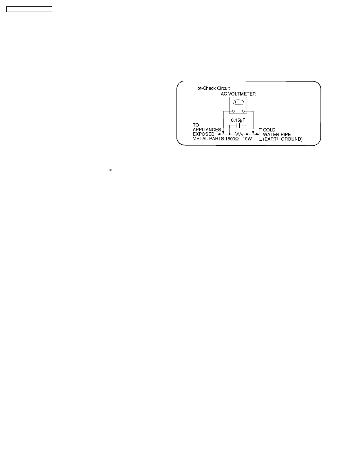
1.1.2. LEAKAGE CURRENT HOT CHECK
1. Plug the AC cord directly into the AC outlet. Do not use an
isolation transformer for this check.
2. Connect a 1.5kΩ, 10 watts resistor, in parallel with a 0.15µF
capacitors, between each exposed metallic part on the set
and a good earth ground such as a water pipe.
3. Use an AC voltmeter, with 1000 ohms/volt or more
sensitivity, to measure the potential across the resistor.
4. Check each exposed metallic part, and measure the
voltage at each point.
5. Reverse the AC plug in the AC outlet and repeat each of the
above measurements.
6. The potential at any point should not exceed 0.75 volts
RMS. A leakage current tester (Simpson Model 229 or
equivalent) may be used to make the hot checks, leakage
current must not exceed 1/2 milliamp. In case a
measurement is outside of the limits specified, there is a
possibility of a shock hazard, and the equipment should be
repaired and rechecked before it is returned to the
customer.
2 PREVENTION OF ELECTRO STATIC DISCHARGE (ESD)
TO ELECTROSTATICALLY SENSITIVE (ES) DEVICES
Some semiconductor (solid state) devices can be damaged easily by static electricity. Such components commonly are called
Electrostatically Sensitive (ES) Devices. Examples of typical ES devices are integrated circuits and some field-effect transistors and
semiconductor "chip" components. The following techniques should be used to help reduce the incidence of component damage
caused by electro static discharge (ESD).
1. Immediately before handling any semiconductor component or semiconductor-equipped assembly, drain off any ESD on your
body by touching a known earth ground. Alternatively, obtain and wear a commercially available discharging ESD wrist strap,
which should be removed for potential shock reasons prior to applying power to the unit under test.
2. After removing an electrical assembly equipped with ES devices, place the assembly on a conductive surface such as alminum
foil, to prevent electrostatic charge buildup or exposure of the assembly.
3. Use only a grounded-tip soldering iron to solder or unsolder ES devices.
4. Use only an anti-static solder removal device. Some solder removal devices not classified as "anti-static (ESD protected)" can
generate electrical charge sufficient to damage ES devices.
5. Do not use freon-propelled chemicals. These can generate electrical charges sufficient to damage ES devices.
6. Do not remove a replacement ES device from its protective package until immediately before you are ready to install it. (Most
replacement ES devices are packaged with leads electrically shorted together by conductive foam, alminum foil or comparable
conductive material).
7. Immediately before removing the protective material from the leads of a replacement ES device, touch the protective material
to the chassis or circuit assembly into which the device will be installed.
Caution
Be sure no power is applied to the chassis or circuit, and observe all other safety precautions.
4
DVD-LS90PP / DVD-LS93P
8. Minimize bodily motions when handling unpackaged replacement ES devices. (Otherwise hamless motion such as the brushing
together of your clothes fabric or the lifting of your foot from a carpeted floor can generate static electricity (ESD) sufficient to
damage an ES device).
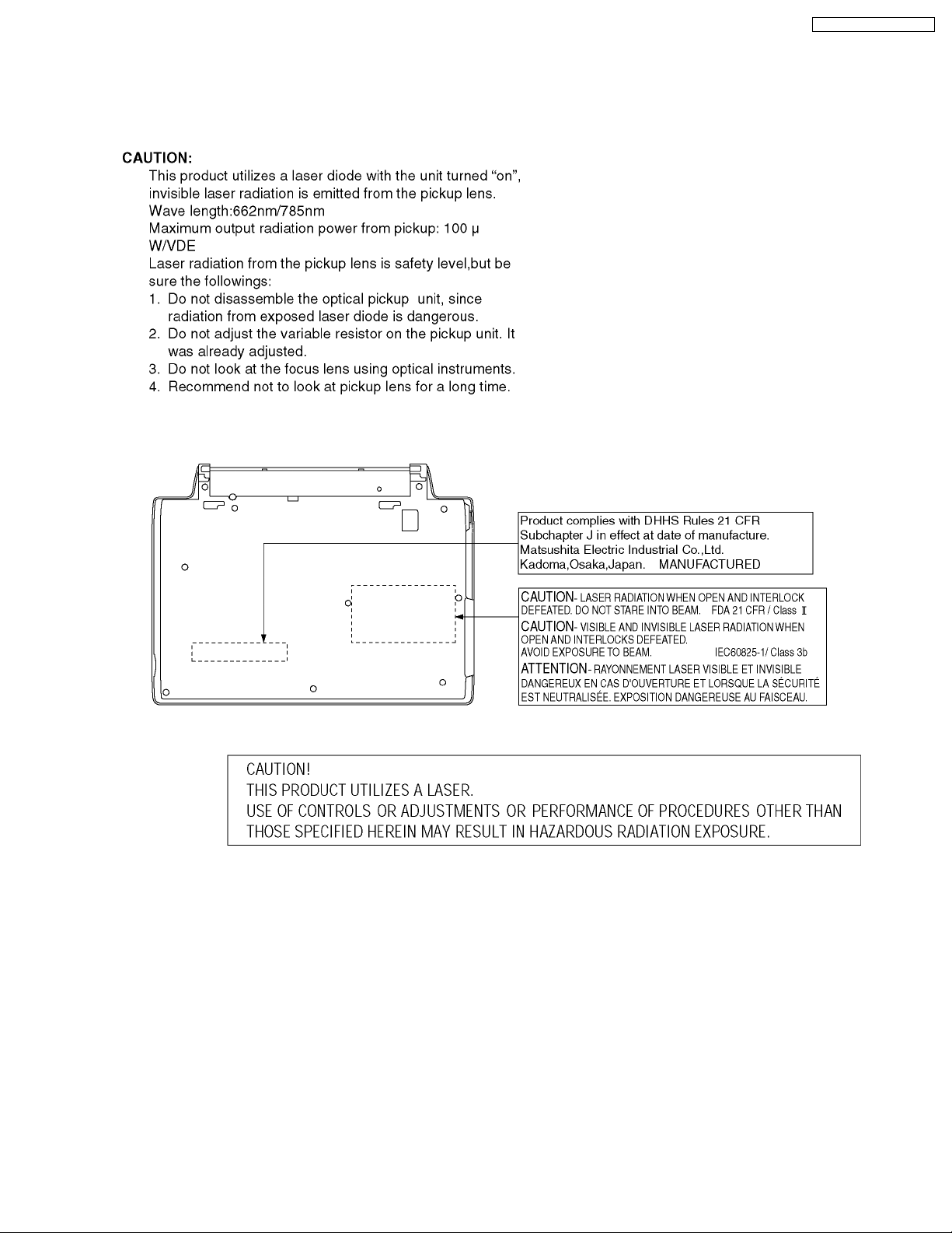
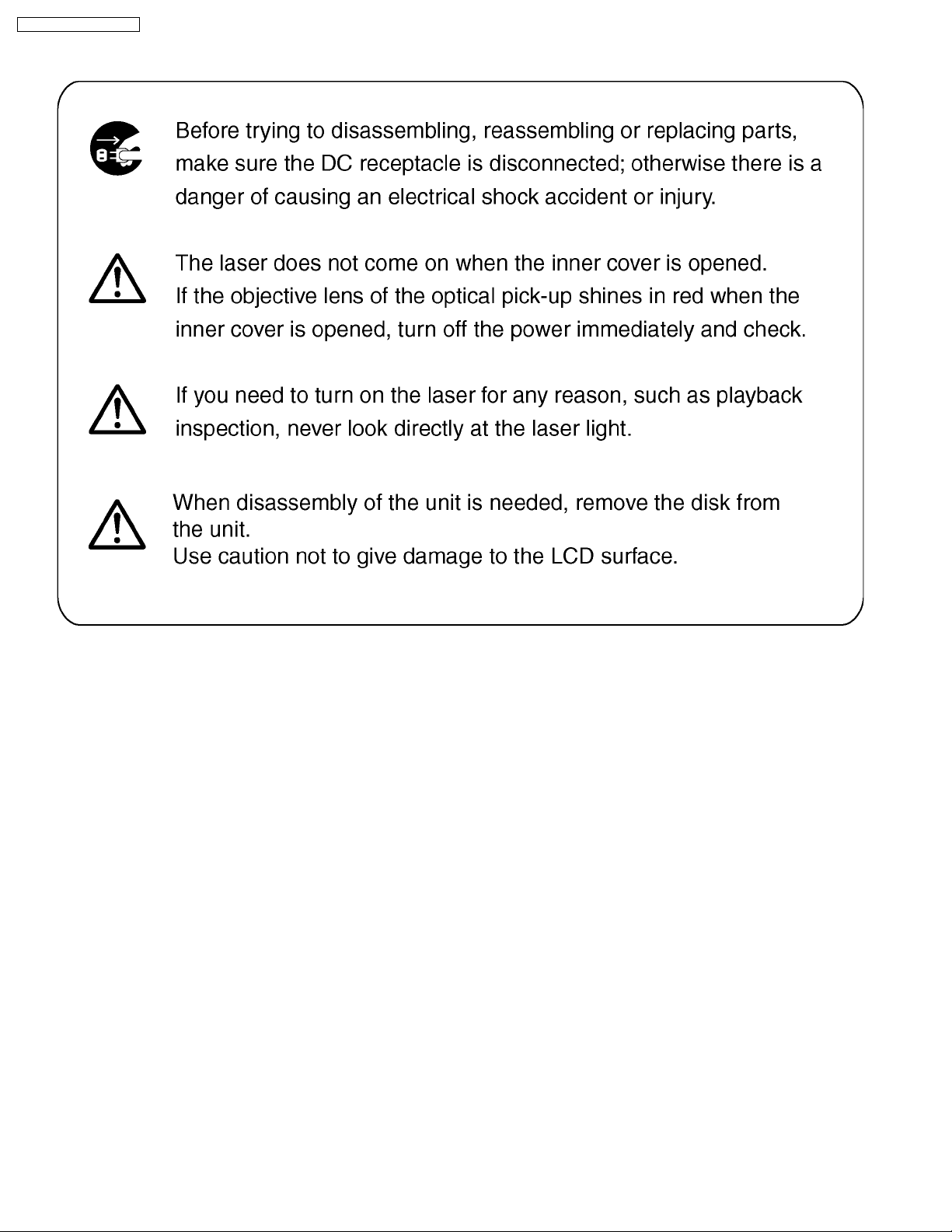
3 PRECAUTION OF LASER DIODE
5
DVD-LS90PP / DVD-LS93P
4 HOW TO REPLACE THE LITHIUM BATTERY
This model is using a lithium battery for the remote control ass’y.
NOTE:
The lithium battery is a critical component. ( Type No.: CR2025 Manufactured by Panasonic. )
It must never be subjected to excessive heat or discharge.
It must therefore only be fitted in equipment designed specifically for its use.
Replacement batteries must be of the same type and manufactu re.
They must be fitted in the same manner and location as the original battery, with the correct polarity contacts observed.
Do not attempt to re-charge the old battery or re-use it for any other purpose.
It should be disposed of in waste products destined for burial rather than incineration.
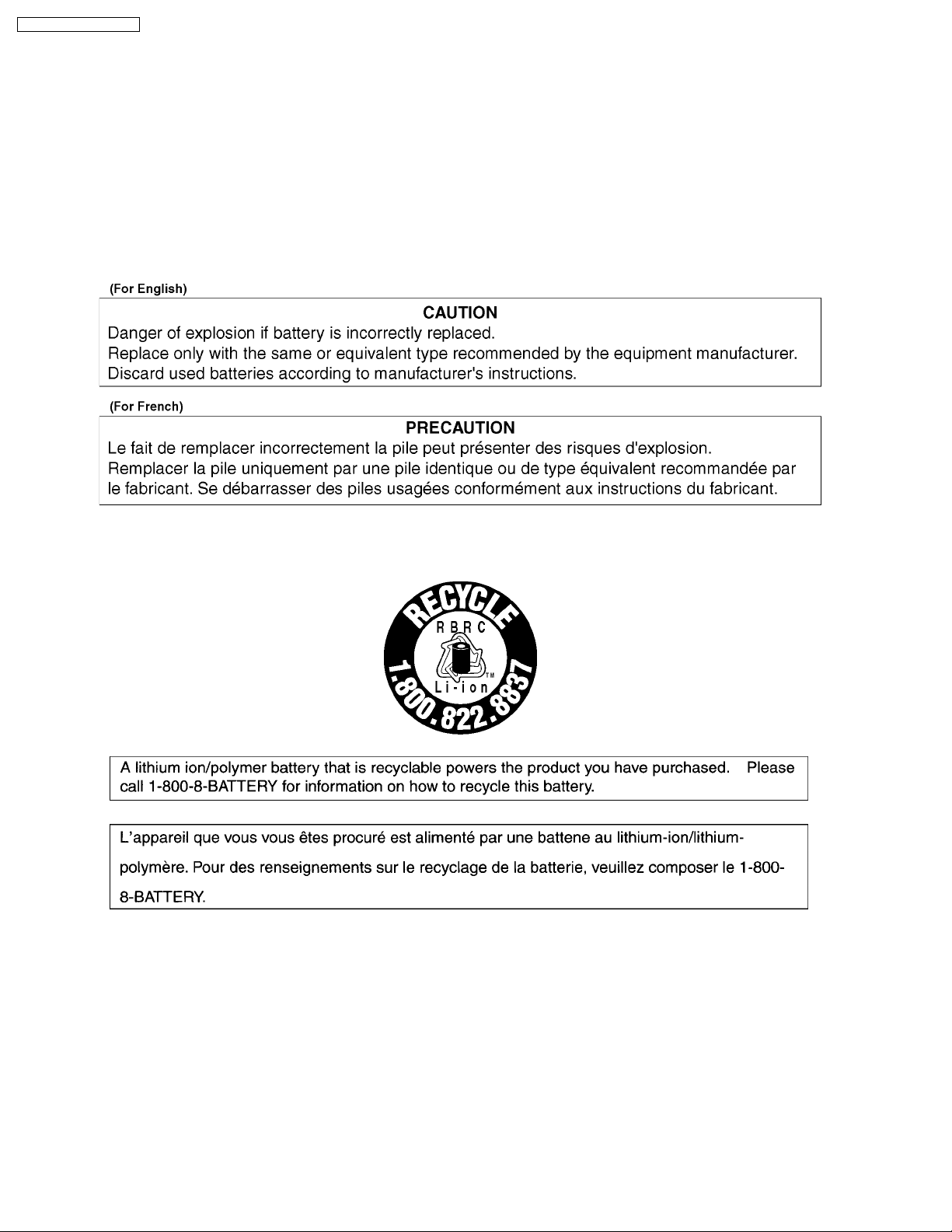
5 LITHIUM ION BATTERY
6 ABOUT LEAD FREE SOLDER (PbF)
Distinction of PbF PCB: PCBs (manufactured) using lead free solder will have a PbF stamp on the PCB.
Caution:
· Pb free solder has a higher melting point than standard solder; Typically thmelting point is 50 - 70°F (30 - 40°C) higher.
Please use a high temperature soldering iron. In case of the soldering iron with temperature control, please set it to 700 ±
20°F (370 ± 10°C).
· Pb free solder will tend to splash when heated too high (about 1100°F/ 600°C).
When soldering or unsoldering, please completely remove all of the solder on the pins or solder area, and be sure to heat the
soldering points with the Pb free solder until it melts enough.
6
7 HANDLING PRECAUTIONS FOR TRAVERSE DECK
DVD-LS90PP / DVD-LS93P
The laser diode in the optical pickup may break down due to
potential difference caused by static electricity of clothes or
human body.
So be careful of electrostatic break down during repair of the
optical pickup.
It has already been adjusted.
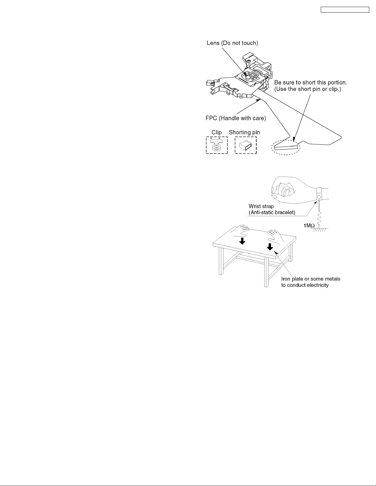
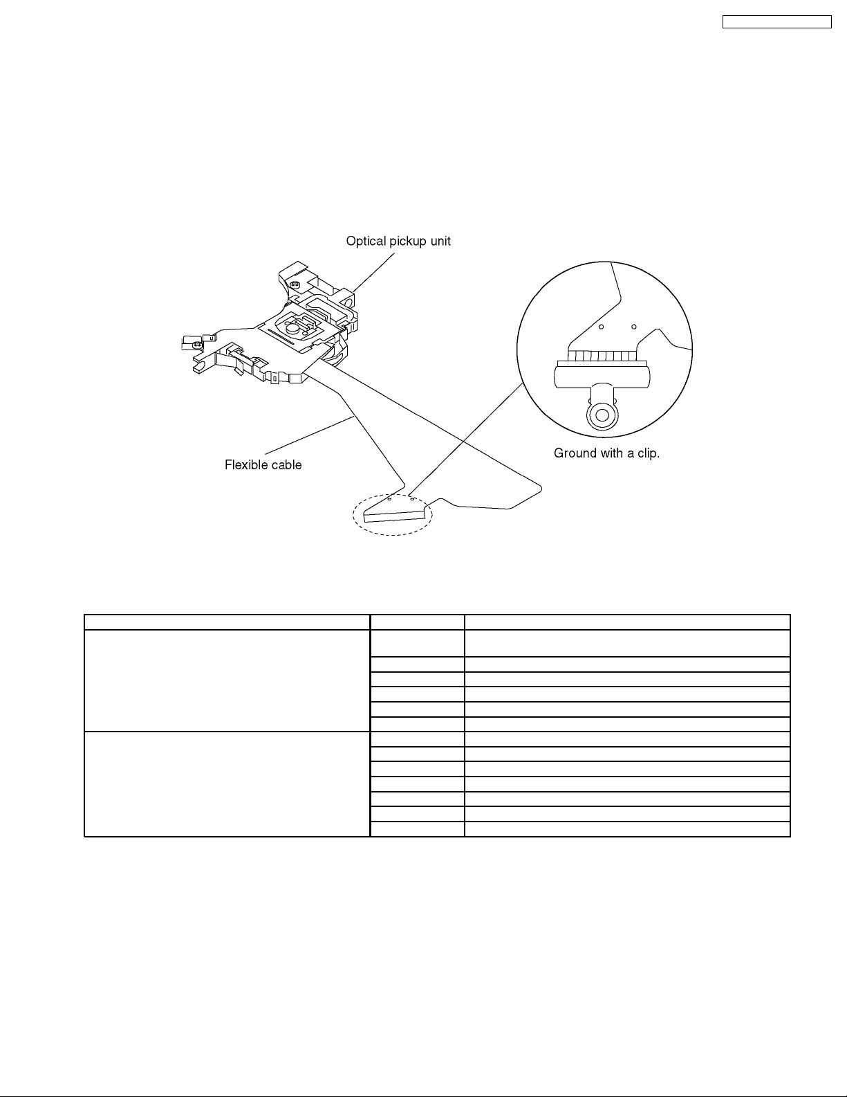
7.1. Handling of optical pickup
1. Do not subject the optical pickup to static electricity as it is
extremely sensitive to electrical shock.
2. To prevent the breakdown of the laser diode, an antistatic
shorting pin is inserted into the flexible board (FPC Board).
When removing or connecting the short pin, finish the job in
as short times as possible.
3. Be careful not to apply excessive stress to the flexible board
(FPC Board).
4. Do not turn the variable resistor (Laser power adjustment).
7.2. Grounding for electrostatic breakdown prevention
1. Human body grounding
Use the antistatic wrist strap to discharge the static
electricity from your body.
2. Work table grounding
Put a conductive material (sheet) or steel sheet on the area
where the optical pickup is placed and ground the sheet.
Caution
The static electricity of your clothes will not be grounded
through the wrist strap. So take care not to let your
clothes touch the optical pickup.
7
DVD-LS90PP / DVD-LS93P
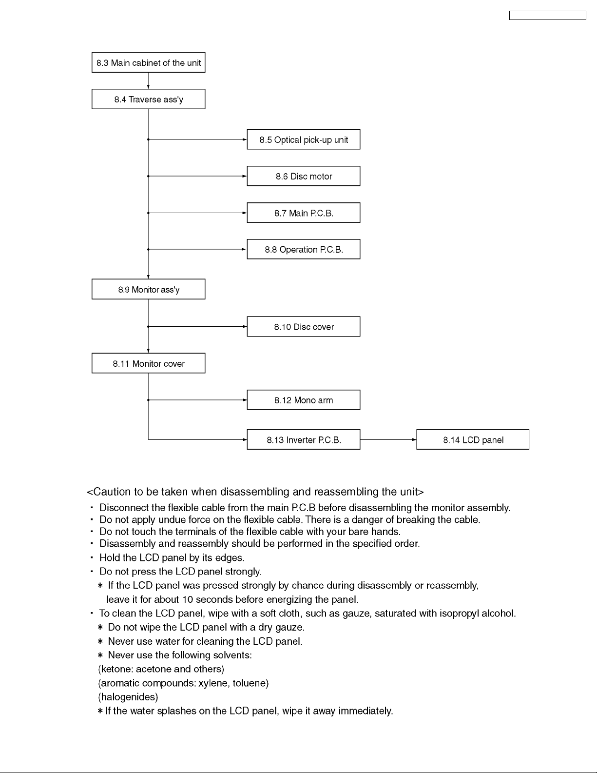
8 DISASSEMBLY, REASSEMBLY AND SERVICE POSITION
8
8.1. Disassembly
DVD-LS90PP / DVD-LS93P
9
DVD-LS90PP / DVD-LS93P
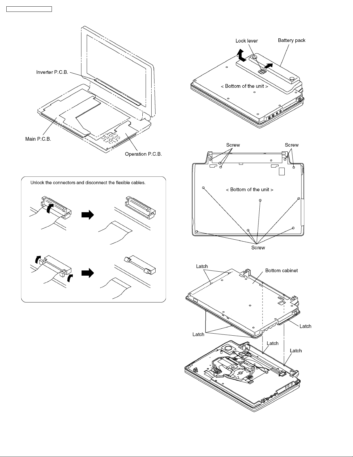
8.2. P.C.B. location
8.3. Main cabinet of the unit
<Removing battery pack>
Release the lock lever and remove the battery pack in the
direction of the arrow.
1. Remove the 11 screws from the bottom of the unit.
2. Release the latches and remove the bottom cabinet.
10
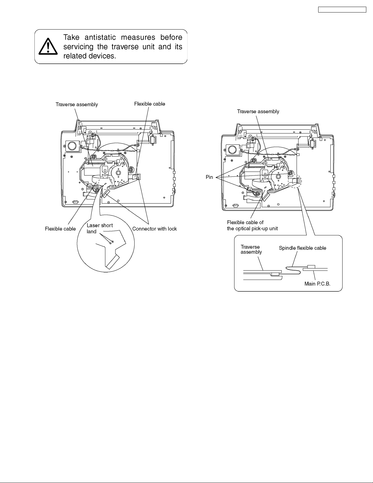
8.4. Traverse assembly
8.4.1. Removing traverse assembly
1. Solder the 2 laser short lands on the flexible cable.
2. Unlock the connectors and remove the flexible cables.
DVD-LS90PP / DVD-LS93P
8.4.2. Reinstalling traverse assembly
1. Reinstall the traverse assembly to the specified pin of the
unit.
2. Reinstall the flexible cable of the optical pickpup unit and
lock it securely.
3. Remove the solder of each laser short land of the flexible
cable.
Caution:
Remove the solders completely: otherwise the laser
diode won’t emit light.
4. Reinstall the spindle flexible cable as shown figure.
11
DVD-LS90PP / DVD-LS93P
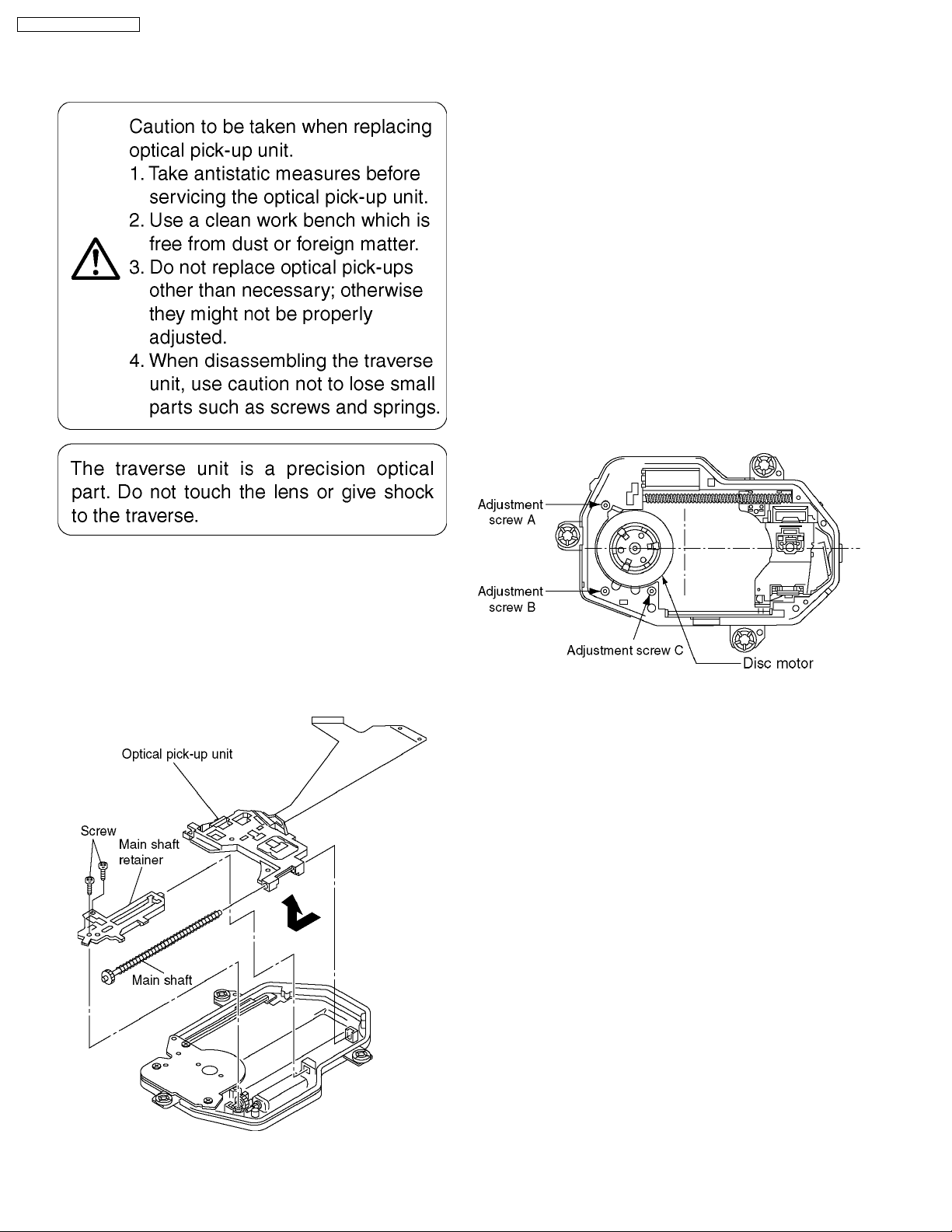
8.5. Optical pick-up unit
8.5.1. Removing optical pick-up unit
8.5.2. Reinstalling optical pick-up unit
The optical pick-up unit is factory adjusted. Do not touch the
adjustment screw.
1. Reassemble the disassembled parts in the reverse order of
disassembly.
2. When reinstalling the traverse assembly on the main unit
after installing the optical pick-up unit, make sure to remove
the solder from each of the two laser short lands on the
flexible cable.
Caution:
· Remove the solders completely; otherwise the laser
diode won´t emit light.
· After replacing the optical pick-up unit, check the quality
of images played back and make optical adjustment.
8.6. Disc motor
8.6.1. Removing disc motor
1. Remove the adjustment screws A, B, and C.
2. Remove the disc motor.
Make sure that the traverse assembly removed before trying to
remove the optical pick-up unit.
When removing the traverse assembly, solder the two laser
short lands on the flexible cable of the optical pick-up unit.
1. Remove the two screws securing the main shaft retainer.
2. Remove the main shaft retainer.
3. Slide the main shaft in the direction indicated by the arrow
to remove the optical pick-up unit.
8.6.2. Caution to be taken when
replacing the disc motor
1. The mounting screws of the disc motor also serve as
adjustment screws. When reinstalling the disc motor, first
turn the screws A, B, and C as far as they go by usual force
to secure them (do not overtighten).
2. Back off the adjustment screws A and C two complete turns
and secure them.
3. Back off the adjustment screw B one and a half turns and
secure them.
· This makes it nearly possible to play back disks and
adjust the jitter.
Thereafter, adjust the adjustment screws C and A as
indicated.
12
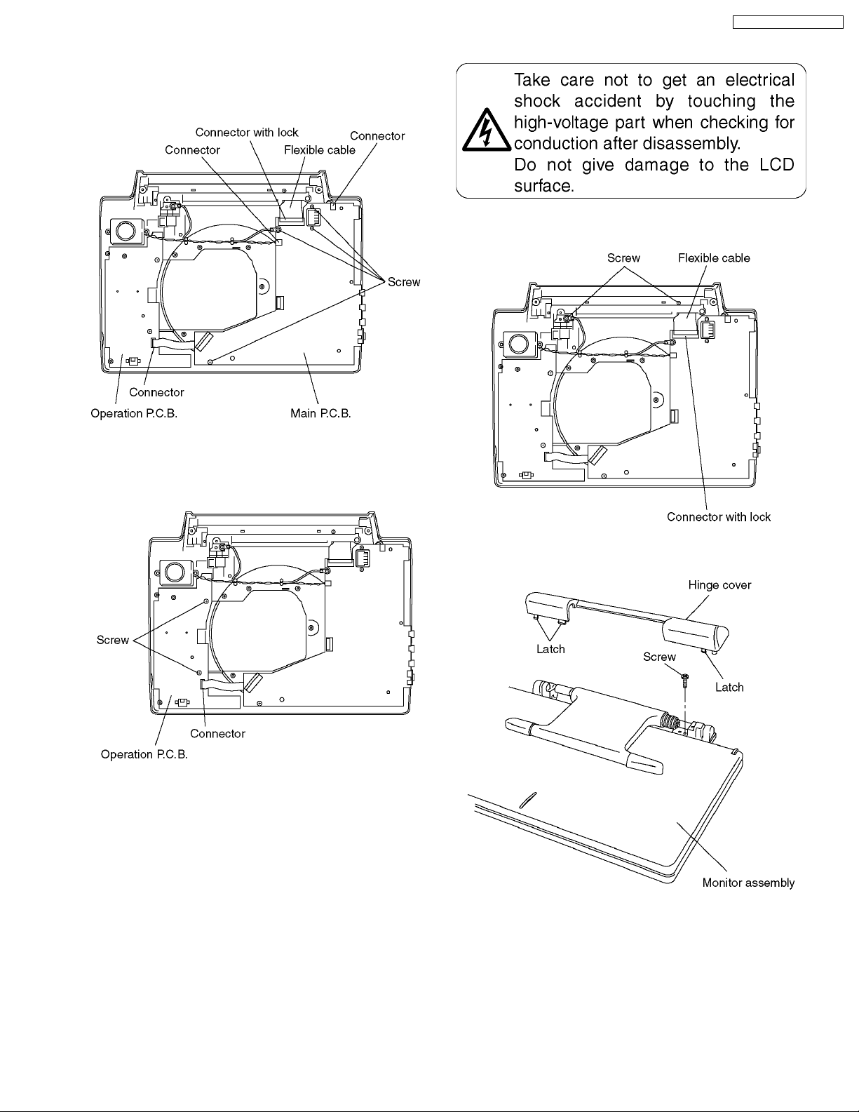
8.7. Main P.C.B.
1. Unlock the connector and remove the flexible cable.
2. Remove the 3 connectors.
3. Remove the 4 screws and remove the main P.C.B..
DVD-LS90PP / DVD-LS93P
8.9. Monitor assembly
1. Unlock the connector and remove the flexible cable.
2. Remove the 2 screws.
8.8. Operation P.C.B.
1. Remove the connector.
2. Remove the 2 screws and remove the operation P.C.B.
3. Release the latches and remove the hinge cover.
4. Remove the screw and remove the monitor assembly.
13
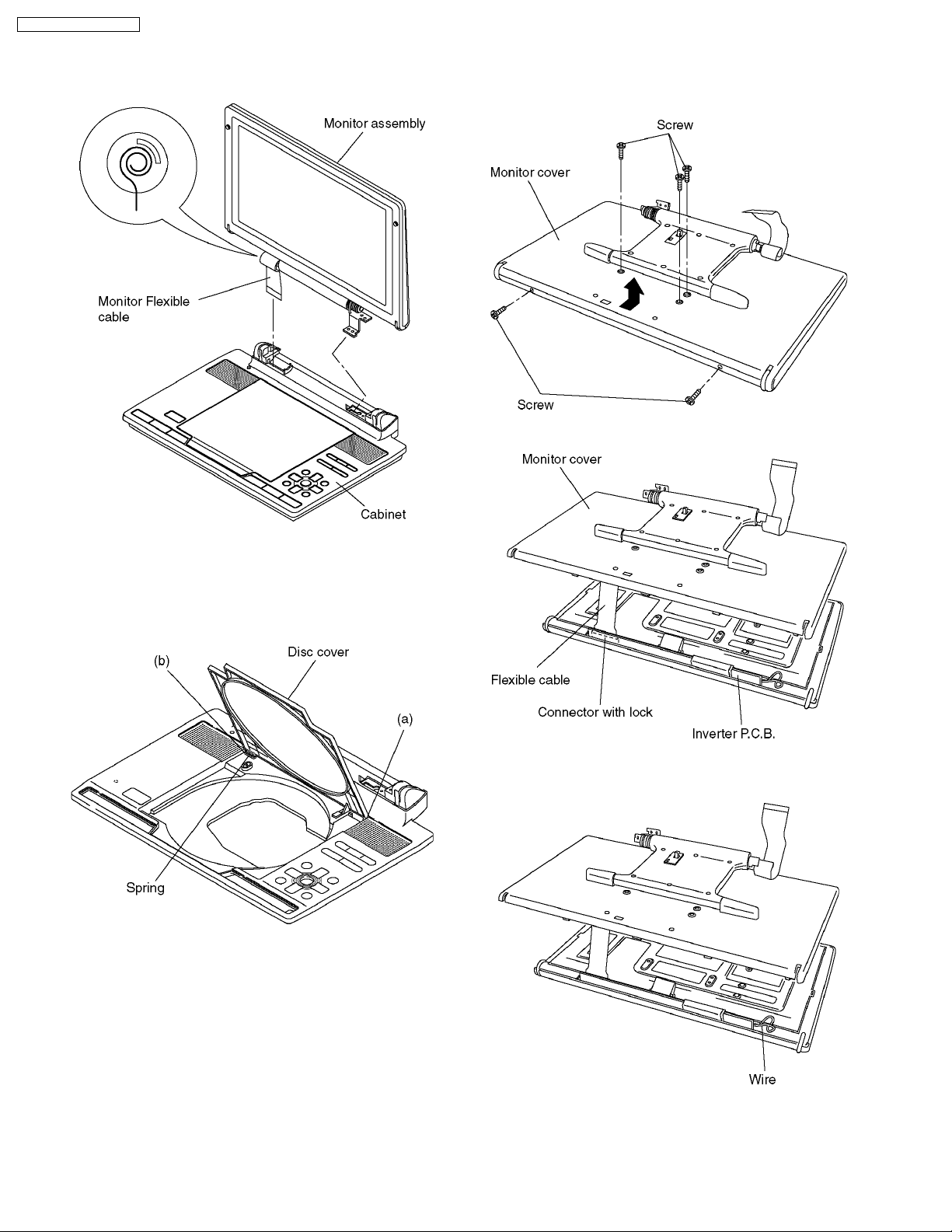
DVD-LS90PP / DVD-LS93P
<Caution to be taken when installing monitor assembly>
1. Roll the flexible cable as shown figure.
2. Install the monitor assembly on the cabinet.
8.11. Monitor cover
1. Remove the 5 screws
2. Remove the monitor cover into the direction of the arrow.
3. Unlock the connector and remove the flexible cable.
8.10. Disc cover
1. Remove the disc cover in order of (a) and (b).
Caution:
Please don’t lose the spring
<Caution to be taken when installing monitor cover>
Please do not nip the wire.
14
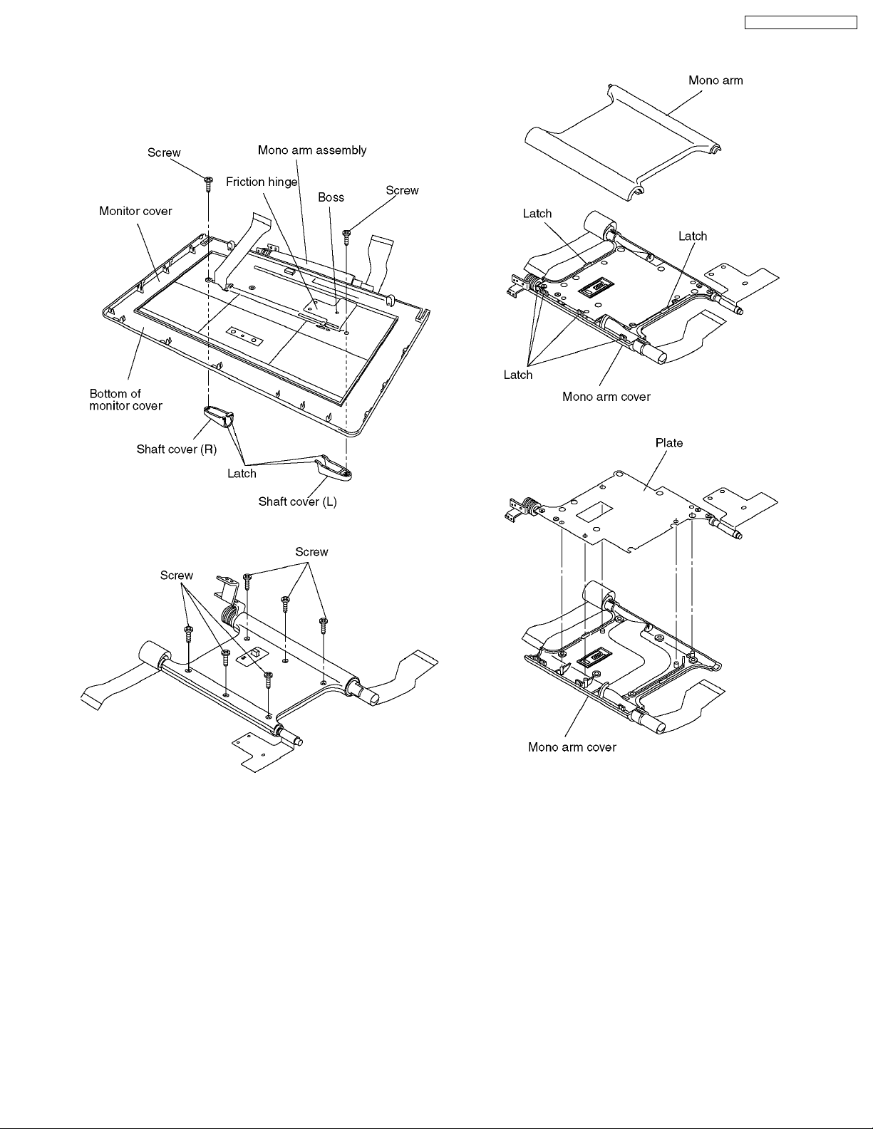
8.12. Mono arm
1. Remove the 2 screws.
2. Release the latches and remove the shaft covers.
3. Release the friction hinge from boss and remove the mono
arm assembly.
DVD-LS90PP / DVD-LS93P
5. Release the latches and remove the mono arm
6. Remove the plate.
4. Remove the 6 screws.
15
DVD-LS90PP / DVD-LS93P
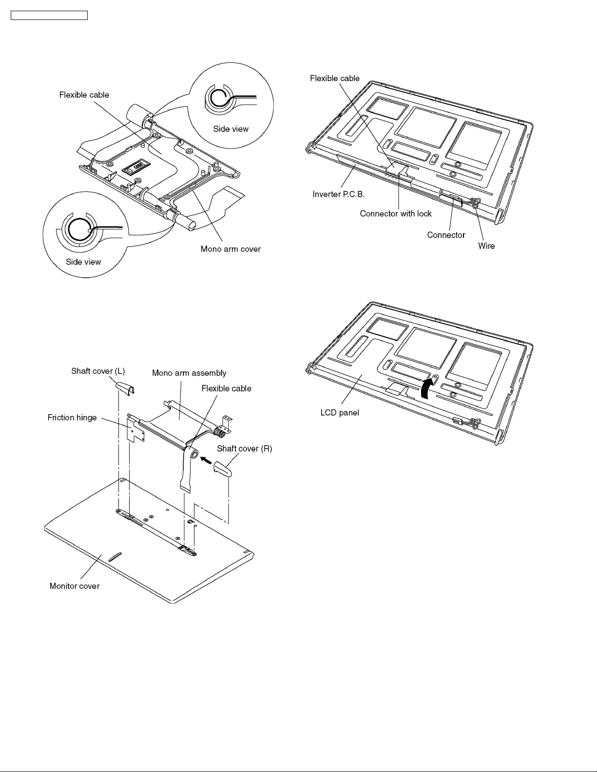
<Caution to be taken when installing mono arm>
1. Roll the flexible cables as shown figure and install it to
mono arm cover.
8.13. Inverter P.C.B.
1. Unlock the connector and remove the flexible cable.
2. Remove the connector and remove the inverter P.C.B.
8.14. LCD panel
2. Install mono arm.
3. Roll 3 turns of the flexible cable and Install the shaft
cover (R) to flexible cable.
4. Pass the flexible cable and the friction hinge into the
holes in the monitor cover.
5. Install the shaft covers to monitor cover.
1. Remove the LCD panel into the direction of the arrow.
16
DVD-LS90PP / DVD-LS93P
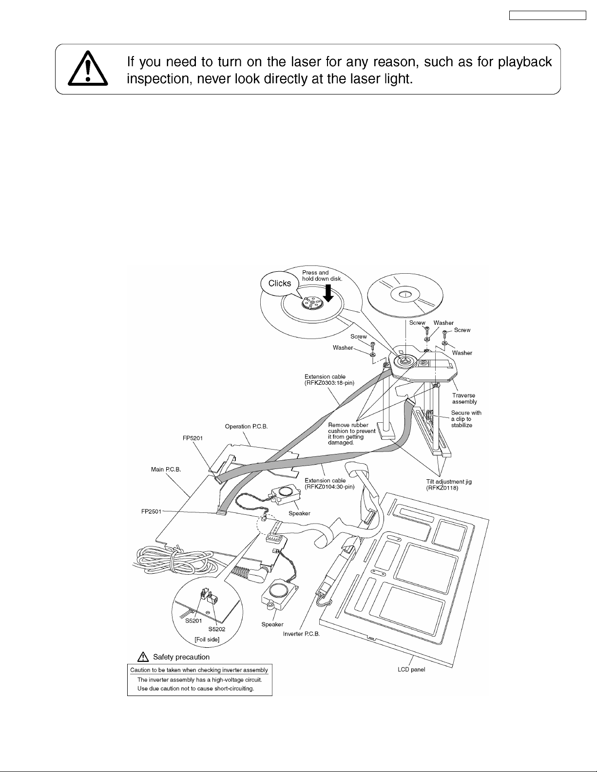
8.15. Service position
8.15.1. Board checks
1. Connect the main P.C.B and the traverse assembly with an extension cable.
2. Install the traverse assembly to the tilt adjustment jig using three screws and three washers.
Caution:
· Remove the rubber cushion from the traverse assembly to prevent it from getting damaged.
3. Install a dick on the traverse assembly.
Caution:
· Make sure the disk is securely installed on the disk motor.
4. Remove the main P.C.B., operation P.C.B., inverter P.C.B., and LCD panel as shown below.
5. The disk cannot be played back with the disk cover removed. Press and hold down the S5201 and S5202. (Secure with
cellulose tape.)
17
DVD-LS90PP / DVD-LS93P
9 SELF-DIAGNOSIS FUNCTION AND SERVICE MODE
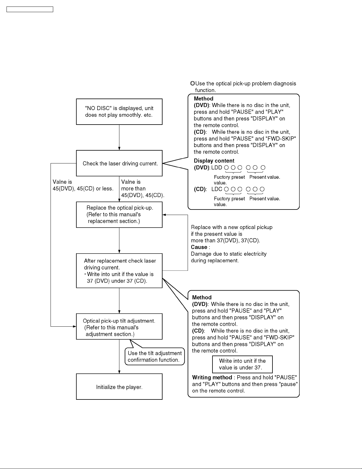
9.1. Optical Pickup Breakdown Diagnosis
As a new feature, this unit has an “optical pick-up problem diagnosis function” and “a tilt adjustment confirmation function” built
in. Use the following procedure to efficiently determine the problem and adjust tilt.If "NO DISC" is displayed, before exchanging
the optical pick-up, carry out problem diagnosis first. If the present laser driving current is over 55, the optical pick-up may need
to be exchanged.
Note:
Carry out diagnosis within 3 minutes of turning the unit on. (The player’s current can increase as it warms up, so turn the unit
off and allow it to cool down before diagnosis.)
18
Cautions to be taken when replacing the optical pickup
The optical pickup may break down due to the static
electricity of human body. Take proper protection measures
against static electricity before repairing the parts around
the optical pickup. (See the page describing the
PREVENTION OF STATIC ELECTRICITY DISCHARGE.)
1. Do not touch the areas around the laser diode and
actuator.
2. Do not judge the laser diode with a tester. (The tester
will be damaged easily.)
3. It is recommended to use a destaticized soldering iron
DVD-LS90PP / DVD-LS93P
for short-circuiting or removing the laser diode.
(Recommended soldering iron) HAKKO ESD Product
4. Solder the land of the flexible cable in the optical pickup.
Note:
· When using a soldering iron which is not
destaticized, short-circuit the terminal face of the
flexible case with a clip. After that, short-circuit
the land.
· After the repairing work is completed, remove the
solder according to the correct procedure shown
in this Technical Guide.
9.2. UHF displays
Use the internal service mode for evaluation of malfunctions.
Display Method Display Diagnosis
Items displa yed when in use CHECK THE
Press the "0" button on the remote control while holding
down the PAUSE and PLAY buttons on the player.
The last error code generated is saved in the EEPROM
DISC
H01 Inner cover trouble
H02 Spindle servo error
H03 Traverse error
H04 Tracking servo error
H05 Seek error
F0** Disc format error
F1** Disc code error
F2** Decoder LSI error
F5** DSC
F6** ECC error
F7** Microcomputer error
F8** Microcomputer error
Focus error
19

DVD-LS90PP / DVD-LS93P
9.3. Service Mode Table 1
The service modes can be activated by pressing various button combination on the player and remote control unit.
Player buttons Remote control unit buttons Application Note
PAUSE
+
PLAY
PAUSE
BWD-SKIP
PLAY
0 Displaying the UHF display F_ _ _ Refer to section 9.2. Self-
5 Jitter check, tilt adjustment
*Display shows xx_yyyzz
"xx" and "zz" shown to the right have nothing to do with the jitter
value. "xx" is the error counter, while "zz" is the focus drive value.
Refer to section 11.4. for Optical Pickup Tilt Adjustment
Procedure.
6 Checking the region numb ers and broadcast system
7 Checking the program version Check the IC6301 FLASH
9 Lighting Confirmation Function of Display Tube
DISPLAY Checking the laser drive current Refer to section 8.5.
PAUSE Writing the laser drive current value after replacing the optical
pickup (do not use for anything other than optical pickup
replacement)
The user setting is returned to the state of the factory shipment. Refer to section 9.6.
—
Diagnosis Function (UHF
Display).
Refer to section 11.4.
Optical Pickup Tilt
Adjustment
ROM program.
Optical Pickup
Replacement Procedure.
Initializing the DVD
player.
9.4. DVD Self Diagnostic Function-Error Code
Error Code Error Content Additional error explanation Defect 1 Defect 2 Defect 3 Defect 4
U, H error
U11 Focus error
H01 Tray loadin g error
H02 Spindle servo error (Spindle servo, DSC SP motor, CLV servo error)
H03 Traverse servo error
H04 Tracking servo error
H05 Seek error
H06 Power error Cannot switch off the power because of the panel
H07 Spindle motor drive
error
DSC related
F500 DSC error DSC stops in the occurence of servo error (starup,
F501 DSC not Ready DSC-system computer communication error
F502 DSC Time out error Similar disposal as F500 OPU DV2
F503 DSC communication
Failure
F505 DSC Attention error Similar disposal as F500 OPU DV2
F506 Invalid media Disc is flipped over, TOC unreadable ,
ODC related
F600 Access failure to
management
information caused by
demodulation error
F601 Indeterminate sector ID
requested
F602 Access failure to LEAD-
IN caused by
demodulation error
F603 Access failure to
KEYDET caused by
demodulation error
F610 ODC abnormality No permission for command execution DV2
F611 6626 QCODE don’t
read Error
and system computer communication error
focus error, etc)
(Communication failure caused by idling of DSC)
Communication error (result error occured
although communication command was sent)
incompatible disc
Operation stopped because navigation data is not
accessible caused by the demodulation defect
Operation stopped caused by the request to
access abnor mal ID data
LEAD IN data unreadable
Access failure to CSS data of disc
Access failure to seek address in CD series DV2
OPU DV2
DV2
(IC3001)
DV2
(IC3001)
DISC DV2
DV2
(IC3001)
DV2
(IC3001)
(IC3001)
(IC3001)
(IC3001)
DV2
(IC3001)
(IC3001)
DV2
(IC3001)
(IC3001)
(IC3001)
DV2
(IC3001)
DV2
(IC3001)
DV2
(IC3001)
DV2
(IC3001)
EEPROM
(IC6351)
DV2
(IC3001)
DV2
(IC3001)
DV2
(IC3001)
DV2
(IC3001)
servo drive
servo drive
servo drive
(IC3001)
DV2
20

DVD-LS90PP / DVD-LS93P
Error Code Error Content Additional error explanation Defect 1 Defect 2 Defect 3 Defect 4
F612 No CRC OK for a
specific time
F630 No reply to KEY DET
enquiry
F631 CPPM KEY DET is not
available till the FILE
terminal
F632 CPPM KEY DET is not
available
Disc code
F103 Illegal highlight Position Big possibility of disc specification violation during
HIC Error
F4FF Force initialize failure
(time out)
Micro computer error
F700 MBX overflow When replying message to disc manager
F701 Message command
does not end
F702 Message command
changes
F880 Task number is not
appropriate
F890 Sending message when
message is being sent
to AV task
F891 Message couldn’t be
sent to AV task
F893 FROM falsification FROM
F894 EEPROM abnormality EEPROM
F895 Language area
abnormality
F896 No existence model Firm version agreement check for factory preset
F897 Initialize is not
completed
F8A0 Message command is
not appropriate
Access failure to ID data in DVD series DV2
(for internal use only)
(CPPM file system is unreadable caused by
scratches)
Been revoked or falsified DISC EEPROM
highlight display
Next message is sent before replying to disc
manager
Message is changed before it is sent as a reply to
disc manager
Message coming from a non-existing task
Sending message to AV task
Begin sending message to AV task
Firm version agreement check for factory preset
setting failure prevention
setting failure prevention
Initialize completion check for factory preset
setting failure prevention
Begin sending message to AV task
(IC3001)
DISC CPPM
(IC6351)
DISC
EEPROM
(IC6351)
(IC6301)
(IC6351)
FROM
(IC6301)
FROM
(IC6301)
(IC3001)
(IC3001)
communicat
ion on lone
DV2
DV2
Serial
CPPM
(*1)
DV2
(IC3001)
DV2
(IC3001)
Note:
An error code will be canceled if a power supply is turned OFF.
*1: CPPM is the copy guard function beforehand written in the disc for protection of copyrights.
9.5. Last Error Code saved during NO PLAY
Error code Error Content
F0BF 6) Cannot playba ck because physical layer is not recoginizable
F0C0 8) DVD: Cannot playback becau se it is not DVD Video/Adio/VR
F0C1 9) DVD: Prohibited by the restricted region code
F0C2 A) DVD: PAL restricted playback
F0C3 B) DVD: Parental lock setting prohibits the playback of the entire title
F0C4 C) VCD: Prohibited because it is in PHOTO CD fromat
F0C5 VCD/CD: Prohibited becau se it is CDROM without CD-DA
21
 Loading...