

Panasonic DVDK-47-GCU, DVDK-47-GCS Service manual
A
V
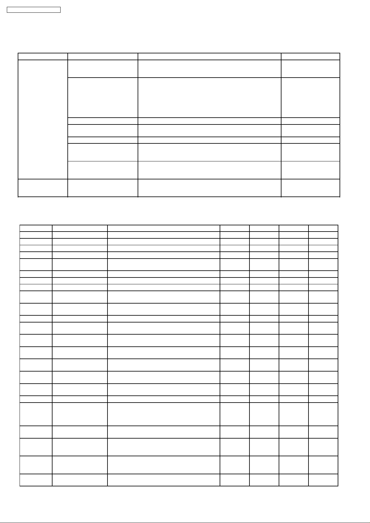
Specifications
Power supply:
Power consumption:
Power consumption in standby mode:
approx. 1 W
Dimensions: 430 (W)×249 (D)×52 (H) mm
Mass:
Signal system:
Operating temperature range: +5 to +35°C
Operating humidity range: 5 to 90 % RH (no
Region number:
Discs played [8 cm or 12 cm]:
(1) DVD-RAM (DVD-VR compatible, JPEG formatted discs)
(2) DVD-Video
(3) DVD-R (DVD-Video compatible)
(4) CD-Audio (CD-DA)
(5) Video CD
(6) SVCD (Conforming to IEC62107)
(7) CD-R/CD-RW (CD-DA, Video CD, SVCD, MP3, WMA,
JPEG formatted discs)
(8) MP3/WMA
lThe total combined maximum number of recognizable
audio and picture contents and groups:
lCompatible compression rate:
MP3: between 32 kbps and 320 kbps
WMA: between 48 kbps and 320 kbps
(9) JPEG
lExif Ver 2.1 JPEG Baseline files
lThe total combined maximum number of recognizable
audio and picture contents and groups:
C220-240V, 50/60Hz
14 W
2.4 kg
PAL625/50, PAL525/60, NTSC
condensation)
Region No.3
4000 audio and picture
contents and 400 groups.
ORDER NO.CHM0406008C3
DVD/CD Player
DVD-K47GCS
DVD-K47GCU
DL2.1T Mechanism Series
Colour
(S).......................Silver Type
4000 audio and picture
contents and 400 groups.
lPicture resolution:
(10) HighMAT Level 2 (Audio and Image)
ideo output:
Output level: 1 Vp-p (75 Ω)
Output terminal: Pin jack (1 system)
S video output:
Y output level: 1 Vp-p (75 Ω)
C output level: NTSC; 0.286 Vp-p (75 Ω)
Output terminal: S terminal (1 system)
Component video output:
Y output level: 1 Vp-p (75 Ω)
PBoutput level: 0.7 Vp-p (75 Ω)
PRoutput level: 0.7 Vp-p (75 Ω)
Output connector: Pin jack (Y: green, PB: blue,
Number of connectors: 1 system
Audio output:
Output level: 2 Vrms (1 kHz, 0 dB)
Output terminal: Pin jack
Number of terminals:
2 channel: 1 system
5.1 channel discrete output
(5.1 channel):
Audio performance:
(1) Frequency response:
lDVD (linear audio):
between 320×240 and
6144×4096 pixels
(Sub sampling is 4:2:2 or 4:2:0)
PAL; 0.300 Vp-p (75 Ω)
P
: red)
R
1 system
4 Hz-22 kHz (48 kHz sampling)
4 Hz-44 kHz (96 kHz sampling)
© 2004 China Hualu Panasonic AVC Networks CO.,
Ltd. All rights reserved. Unauthorized copying and
distribution is a violation of law.
DVD-K47GCS / DVD-K47GCU
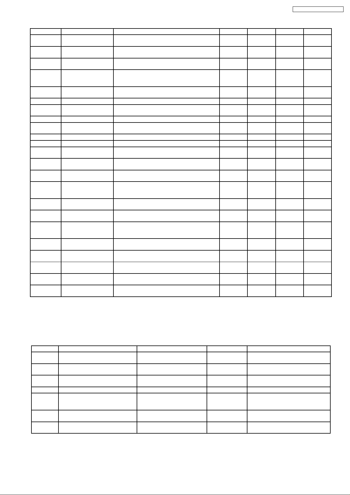
lCD audio:
(2) S/N ratio:
lCD audio:
(3) Dynamic range:
lDVD (linear audio):
lCD audio:
(4) Total harmonic distortion:
lCD audio:
Digital audio output:
Optical digital output: Optical terminal
Coaxial digital output: Pin jack
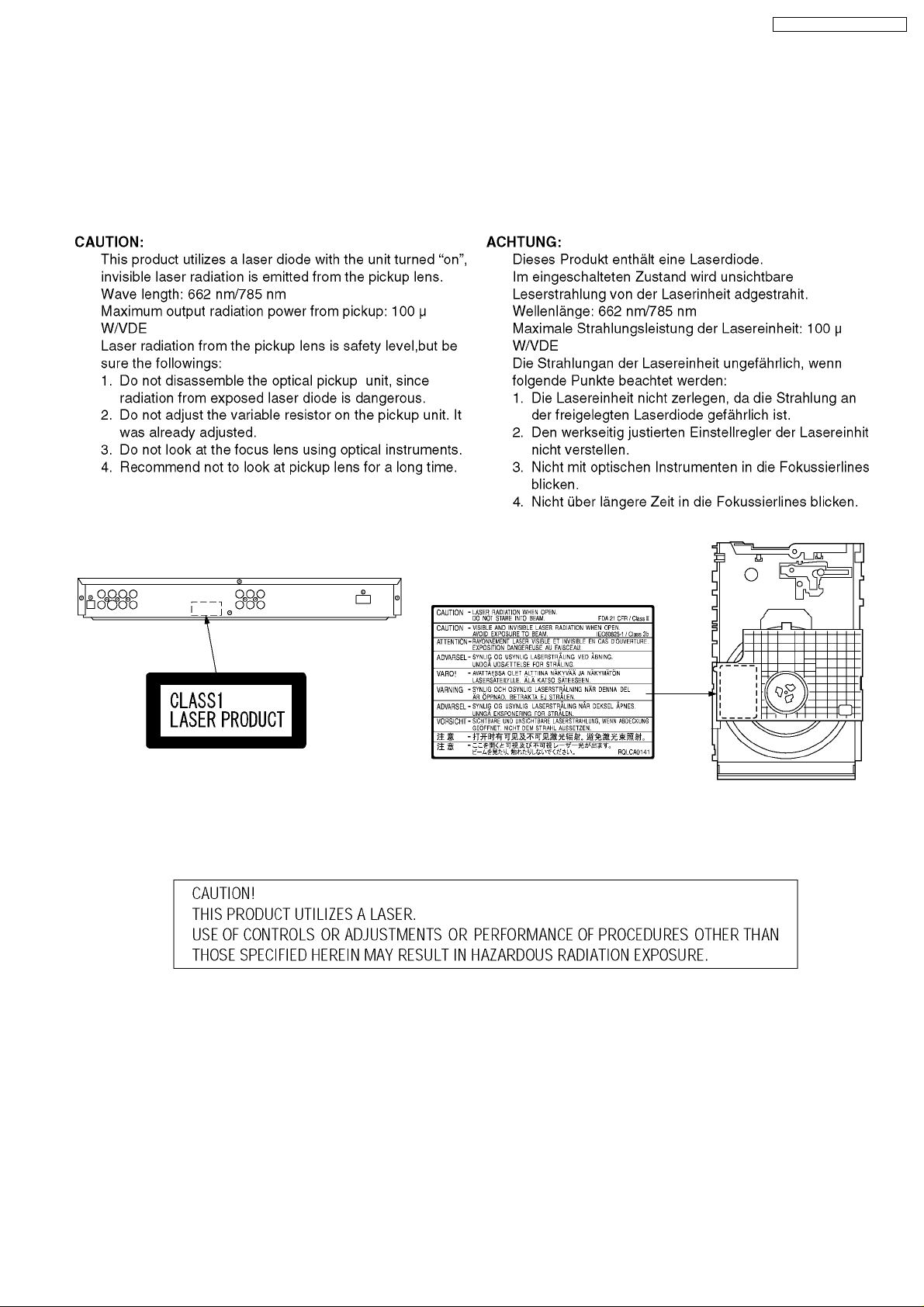
Pickup
Wave length: 662 nm/785 nm
Laser power: CLASS 2/CLASS 3A
Note:
Specifications are subject to change without notice.
Solder:
4 Hz-20 kHz
115 dB
100 dB
98 dB
0.0025 %
Mass and dimensions are approximate.
This model uses lead free solder (PbF).
CONTENTS
Page Page
1 SAFETY PRECAUTIONS 4
1.1. GENERAL GUIDELINES
2 PREVENTION OF ELECTRO STATIC DISCHARGE (ESD) TO
ELECTROSTATICALLY SENSITIVE (ES) DEVICES
3 Precaution of Laser Diode
4 About lead free solder (PbF)
5 PREVENTION OF STATIC ELECTRICITY DISCHARGE
5.1. Grounding for electrostatic breakdown prevention
5.2. Handling Precautions for Traverse Unit (Optical Pickup)
6 DISASSEMBLING THE CASING AND CHECKING P.C.B.S
6.1. Disassembly Procedure
6.2. Casing Parts and P.C.B. Positions
6.3. Top Panel
6.4. Tray (When taking out disc manually)
6.5. Front Panel
6.6. Module P.C.B.
6.7. Mic P.C.B., Front (L) P.C.B. and Front (R) P.C.B.
6.8. Mechanism Unit
6.9. Rear panel
6.10. Power supply P.C.B.
6.11. Mother P.C.B.
6.12. 5.1CH P.C.B.
6.13. Service Position
7 ASSEMBLING AND DISASSEMBLING THE MECHANISM UNIT
10
10
10
10
10
11
12
4
4
5
5
6
6
6
7
7
7
8
8
8
9
9
7.1. Disassembly Procedure 12
7.2. Traverse Unit
7.3. Tray
7.4. Loading section
7.5. Intermediate P.C.B.
7.6. Optical Pickup Unit
7.7. Traverse Motor and Spindle Motor
8 Self-Diagnosis Function and Service Modes
8.1. Optical Pickup Breakdown Diagnosis
8.2. Service Mode Table 1
8.3. DVD Self Diagnostic Function-Error Code
8.4. Last Error Code saved during NO PLAY
8.5. Service mode table 2
8.6. Sales demonstration lock function
8.7. Handling After Completing Repairs
9 Service Precautions
9.1. Recovery after the dvd player is repaired
9.2. Firmware version-up of the DVD player
10 ADJUSTMENT PROCEDURES
10.1. Service Tools and Equipment
10.2. Important points in adjustment
10.3. Storing and Handling Test Discs
10.4. Optical adjustment
11 Abbreviations
12 VOLTAGE CHART
12
13
14
15
16
19
21
21
22
22
23
24
26
26
27
27
27
28
28
28
28
29
30
32
2

DVD-K47GCS / DVD-K47GCU
12.1. POWER SUPPLY P.C.B. 32
12.2. MODULE P.C.B.
12.3. MOTHER P.C.B.
12.4. OPERATION (L) P.C.B.
12.5. 5.1CH P.C.B.
12.6. MIC P.C.B.
13 BLOCK DIAGRAM
13.1. OVERALL BLOCK DIAGRAM
13.2. POWER SUPPLY BLOCK DIAGRAM
13.3. SERVO BLOCK DIAGRAM
13.4. VIDEO BLOCK DIAGRAM
13.5. AUDIO BLOCK DIAGRAM
14 INTERCON NECTION SCHEMATIC DIAGRAM & SCHEMATIC
DIAGRAM NOTES
14.1. INTERCONNECTION SCHEMATIC DIAGRAM
14.2. SCHEMATIC DIAGRAM NOTES
15 SCHEMAT IC DIAGRAM
15.1. POWER SUPPLY SCHEMATIC DIAGRAM
15.2. INTERMEDIATE SCHEMATIC DIAGRAM
15.3. I/O SECTION (MODULE P.C.B. (1/2)) SCHEMATIC
DIAGRAM
15.4. DV2 SECTION (MODULE P.C.B. (2/2)) SCHEMATIC
DIAGRAM
15.5. VIDEO OUT SECTION (MOTHER P.C.B. (1/4))
SCHEMATIC DIAGRAM
15.6. AUDIO OUT1 SECTION (MOTHER P.C.B. (2/4))
32
34
34
35
35
37
37
38
39
16 PRINT CIRCUIT BOARD
40
42
SCHEMATIC DIAGRAM
15.7. AUDIO OUT2 SECTION (MOTHER P.C.B. (3/4))
SCHEMATIC DIAGRAM
15.8. OPERATION SECTION (MOTHER P.C.B. (4/4))
SCHEMATIC DIAGRAM
15.9. FRONT (L) / FRONT (R) SCHEMATIC DIAGRAM
15.10. 5.1CH SCHEMATIC DIAGRAM
15.11. MIC SCHEMATIC DIAGRAM
16.1. POWER SUPPLY P.C.B.
16.2. INTERMEDIATE P.C.B.
16.3. MODULE P.C.B. (1/2) (COMPONENT SIDE)
43
43
44
45
45
46
16.4. MODULE P.C.B. (2/2) (FOIL SIDE)
16.5. MODULE P.C.B. & MOTHER P.C.B. ADDRESS
INFORMATION
16.6. MOTHER P.C.B.
16.7. FRONT (L) / FRONT (R) P.C.B.
16.8. 5.1CH P.C.B. & MIC P.C.B.
17 EXPLODED VIEWS
47
17.1. Casing Parts & Mechanism Section Exploded View
17.2. Mechanism Section Exploded View
48
17.3. Packing & Accessories Section Exploded View
18 REPLACEM ENT PARTS LIST
49
50
51
52
53
54
55
57
57
58
59
60
61
62
63
64
65
65
66
67
68
3
DVD-K47GCS / DVD-K47GCU
1 SAFETY PRECAUTIONS
1.1. GENERAL GUIDELINES
1. When servicing, observe the original lead dress. If a short circuit is found, replace all parts which have been overheated or
damaged by the short circuit.
2. After servicing, see to it that all the protective devices such as insulation barriers, insulation papers shields are properly
installed.
3. After servicing, make the following leakage current checks to prevent the customer from being exposed to shock hazards.
1.1.1. LEAKAGE CURRENT COLD
CHECK
1. Unplug the AC cord and connect a jumper between the two
prongs on the plug.
2. Measure the resistance value, with an ohmmeter, between
the jumpered AC plug and each exposed metallic cabinet
part on the equipment such as screwheads, connectors,
control shafts, etc. When the exposed metallic part has a
return path to thechassis, the reading should be between
1MΩand 5.2MΩ.
When the exposed metal does not have a return path to
the chassis, the reading must be
Figure 1
.
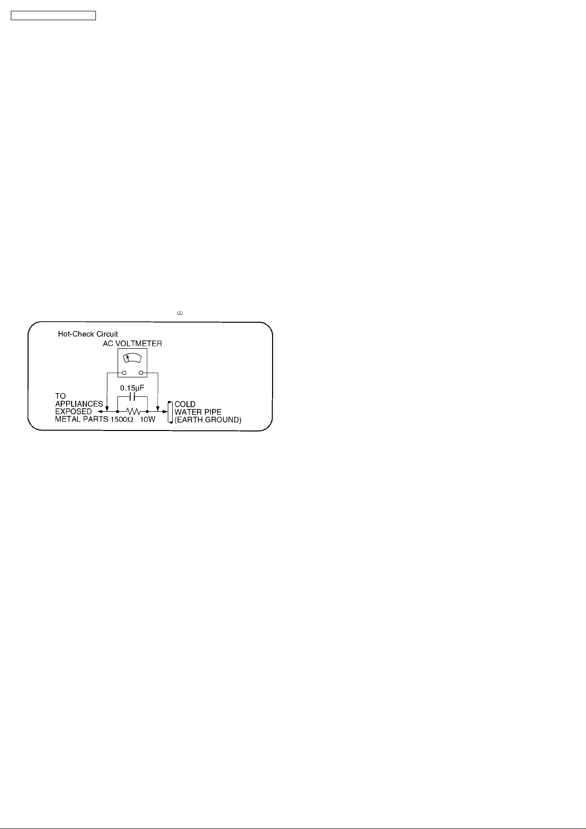
1.1.2. LEAKAGE CURRENT HOT CHECK
(See Figure 1 .)
1. Plug the AC cord directly into the AC outlet. Do not use an
isolation transformer for this check.
2. Connect a 1.5kΩ, 10 watts resistor, in parallel with a 0.15µF
capacitors, between each exposed metallic part on the set
and a good earth ground such as a water pipe, as shown in
Figure 1 .
3. Use an AC voltmeter, with 1000 ohms/volt or more
sensitivity, to measure the potential across the resistor.
4. Check each exposed metallic part, and measure the
voltage at each point.
5. Reverse the ACplug inthe AC outlet and repeat each of the
above measurements.
6. The potential at any point should not exceed 0.75 volts
RMS. A leakage current tester (Simpson Model 229 or
equivalent) may be used to make the hot checks, leakage
current mu3st not exceed 1/2 milliamp. In case a
measurement is outsideof the limits specified, there is a
possibility of a shock hazard, and the equipment should be
repaired and rechecked before it is returned to the
customer.
2 PREVENTION OF ELECTRO STATIC DISCHARGE (ESD)
TO ELECTROSTATICALLY SENSITIVE (ES) DEVICES
Some semiconductor (solid state) devices can be damaged easily by static electricity. Such components commonly are called
Electrostatically Sensitive (ES) Devices. Examples of typical ES devices are integrated circuits and some field-effect transistorsand
semiconductor
caused by electro static discharge (ESD).
1. Immediately before handling any semiconductor component or semiconductor-equipped assembly, drain off any ESD on your
body by touching a known earth ground. Alternatively, obtain and wear a commercially available dischargingESD wrist strap,
which should be removed for potential shock reasons prior to applying power to the unit under test.
2. After removing an electrical assembly equipped with ES devices, place the assembly on a conductive surface such as alminum
foil, to prevent electrostatic charge buildup or exposure of the assembly.
3. Use only a grounded-tip soldering iron to solder or unsolder ES devices.
4. Use only an anti-static solder removal device. Some solder removal devices not classified as "anti-static (ESD protected)" can
generate electrical charge sufficient to damage ES devices.
5. Do not use freon-propelled chemicals. These can generate electrical charges sufficient to damage ES devices.
6. Do not remove a replacement ES device from its protective package until immediately before you are ready to install it. (Most
replacement ES devices are packaged with leads electrically shorted together by conductive foam, alminum foil or
comparableconductive material).
7. Immediately before removing the protective material from the leads of a replacement ES device, touch the protec tive material
to the chassis or circuit assembly into which the device will be installed.
"chip" components. The following techniques should be used to help reduce the incidence of component damage
4
DVD-K47GCS / DVD-K47GCU
Caution
Be sure no power is applied to the chassis or circuit, and observe all other safety precautions.
8. Minimize bodily motions when handling unpackaged replacement ES devices. (Otherwise hamless motion such as the brushing
together of your clothes fabric or the lifting of your foot from a carpeted floor can generate static electricity (ESD) sufficient
todamage an ES device).
3 Precaution of Laser Diode
4 About lead free solder (PbF)
Caution:
· Pb free solder has a higher melting point than standard solder; Typically thmelting point is 50 - 70°F (30 - 40°C) higher.
Please use a high temperature soldering iron. In case of the soldering iron with temperature control,please set it to 700 ±
20°F (370 ± 10°C).
· Pb free solder will tend to splash when heated too high (about 1100°F/ 600°C).
When soldering or unsoldering, please completely remove all of the solder on the pins or solder area, and be sure to heat the
soldering points with the Pb free solder until it melts enough.
5
DVD-K47GCS / DVD-K47GCU
5 PREVENTION OF STATIC ELECTRICITY DISCHARGE
The laser diode in the traverse unit (optical pickup) may brake down due to static electricity of clothes or human body. Use due
caution to electrostatic breakdown when servicing and handling the laser diode.
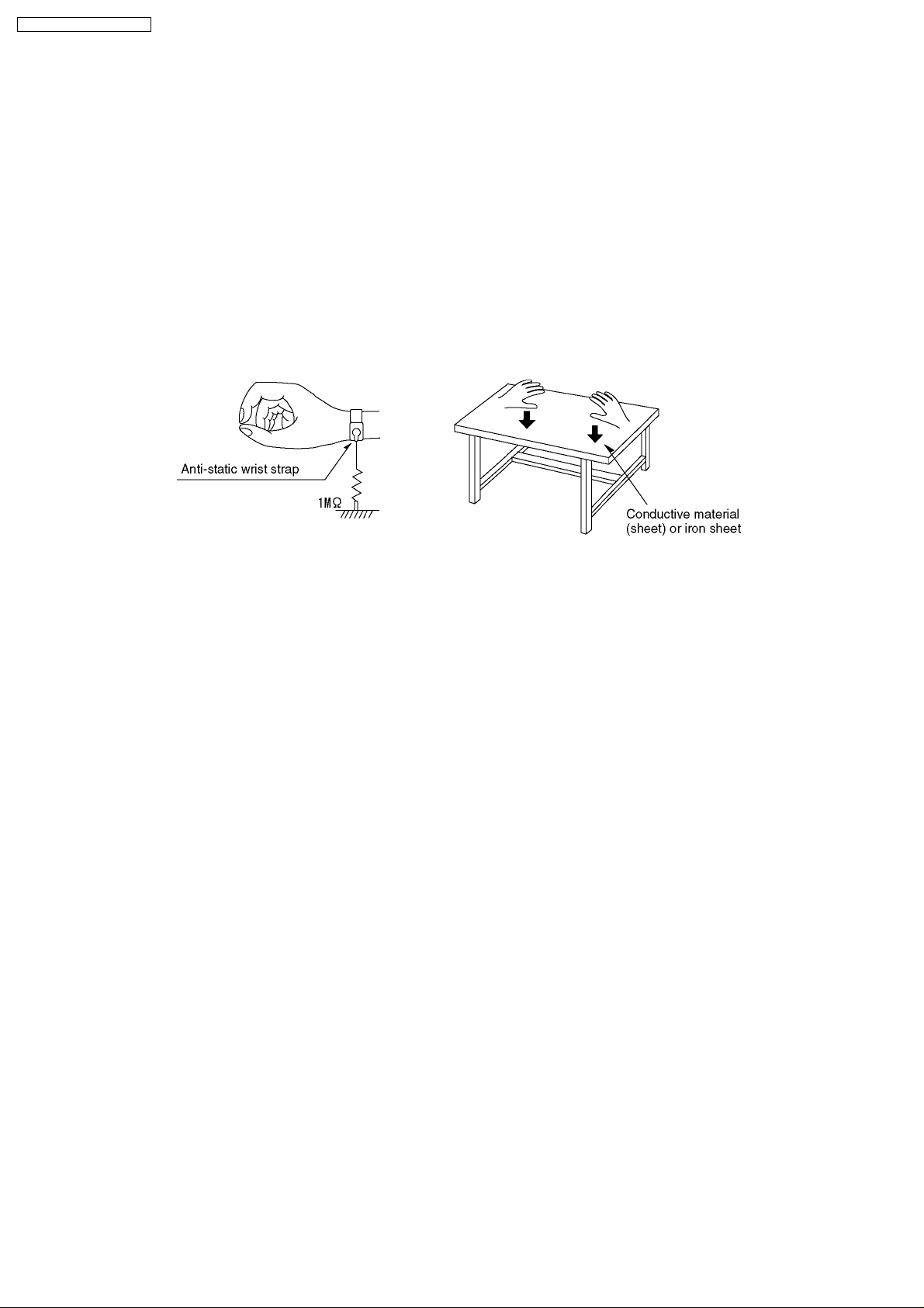
5.1. Grounding for electrostatic breakdown prevention
Some devices such as the DVD player use the optical pickup (laser diode) and the optical pickup will be damaged by static
electricity in the working environment. Proceed servicing works under the working environment where grounding works is
completed.
5.1.1. Worktable grounding
1. Put a conductive material (sheet) or iron sheet on the area where the optical pickup is placed, and ground the sheet.
5.1.2. Human body grounding
1. Use the anti-static wrist strap to discharge the static electricity form your body.
5.1.3. Handling of optical pickup
1. To keep the good quality of the optical pickup maintenance parts during transportation and before installation, the both ends of
the laser diode are short-circuited. After replacing the parts with new ones, remove the short circuit accordingto the correct
procedure. (See this Technical Guide.)
2. Do not use a tester to check the laser diode for the optical pickup. Failure to do so will damage the laser diode due to the power
supply in the tester.
5.2. Handling Precautions for Traverse Unit (Optical Pickup)
1. Do not give a considerable shock to the traverse unit (optical pickup) as it has an extremely high-precise structure.
2. When replacing the optical pickup, install the flexible cable and cut its short land with a nipper. See the optical pickup
replacement procedure in this Technical Guide. Before replacing the traverse unit, remove the short pin for preventingstatic
electricity and install a new unit. Connect the connector as short times as possible.
3. The flexible cable may be cut off if an excessive force is applied to it. Use caution when handling the cable.
4. The half-fixed resistor for laser power adjustment cannot be adjusted. Do not turn the resistor.
6
DVD-K47GCS / DVD-K47GCU
6 DISASSEMBLING THE CASING AND CHECKING P.C.B.S
6.1. Disassembly Procedure
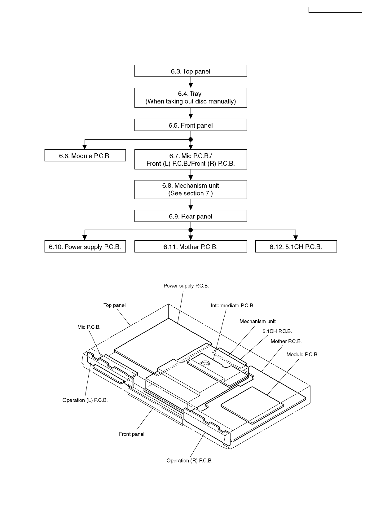
6.2. Casing Parts and P.C.B. Positions
7
DVD-K47GCS / DVD-K47GCU
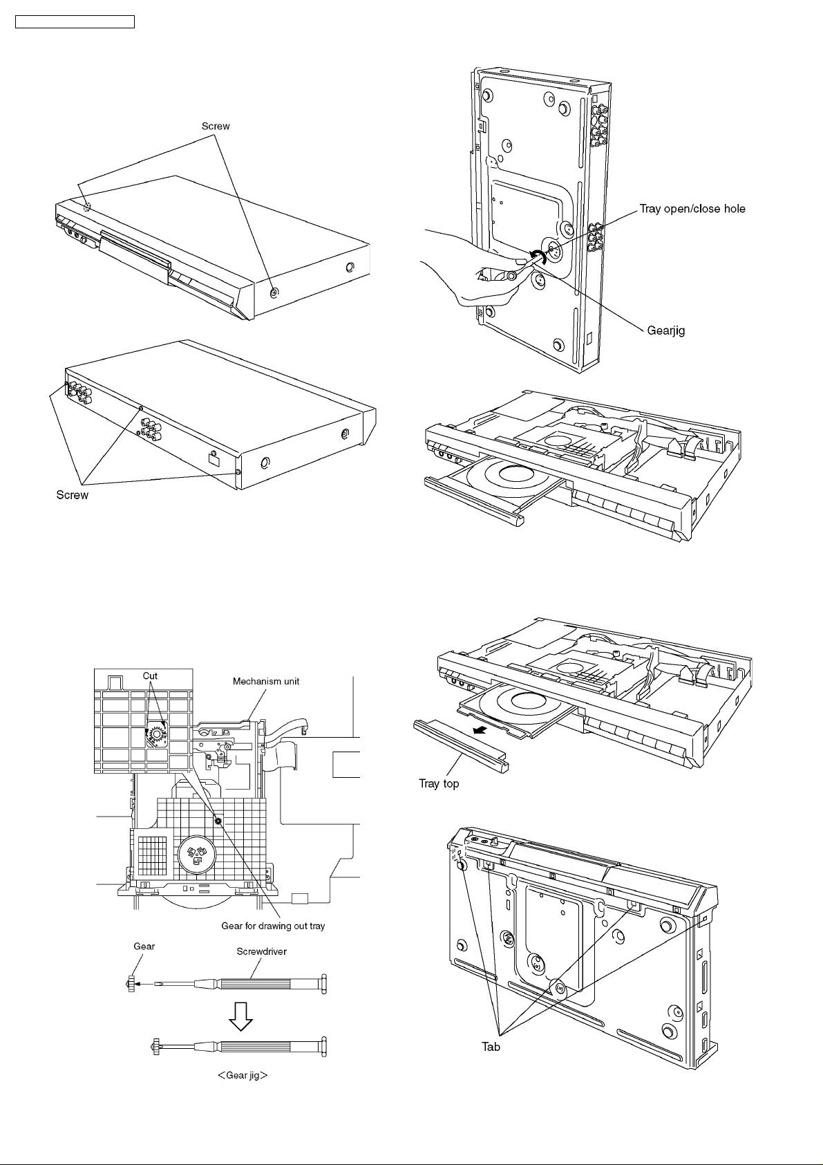
6.3. Top Panel
1. Unscrew the screws.
6.4. Tray (When taking out disc
manually)
1. Separates the gear for drawing out tray from the
mechanism unit. It inserts a screwdriver in the gear. (The
gear jig)
2. Insert the gear jig into the tray open/ close hole.
3. Turn the gear jig counterclockwise to open the tray.
6.5. Front Panel
1. Remove the tray top from the tray section.
2. Release the tabs.
8
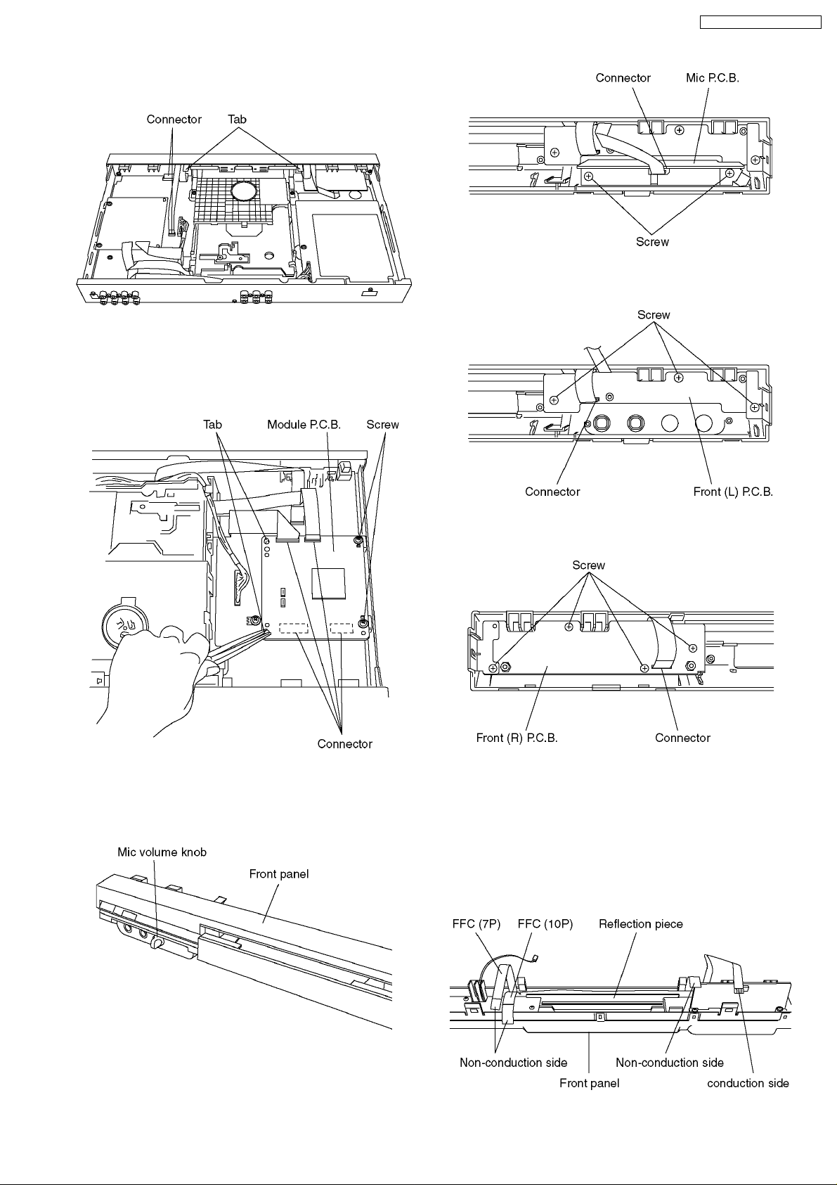
3. Release the tabs.
4. Remove the connectors.
6.6. Module P.C.B.
1. Unscrew the screws.
2. Remove the connectors.
3. Press each tab with the nipper to module PCB vertically.
DVD-K47GCS / DVD-K47GCU
4. Unscrew the screws.
5. Remove the connector.
6.7. Mic P.C.B., Front (L) P.C.B.
and Front (R) P.C.B.
1. Remove the mic volume knob.
6. Unscrew the screws.
7. Remove the connector.
<Cation to taken ehen insetting front panel>
1. FFC (10P) is an inner side and FFC (7P) is an outside.
It inserts in the crevice between a reflection piece and a
front panel.
2. Direction of an electrical conduction side and nonelectrical conduction side is checked.
3. The position of right and left of FFC is made into the
position which can be inserted in a connector.
2. Unscrew the screws.
3. Remove the connector.
9
DVD-K47GCS / DVD-K47GCU
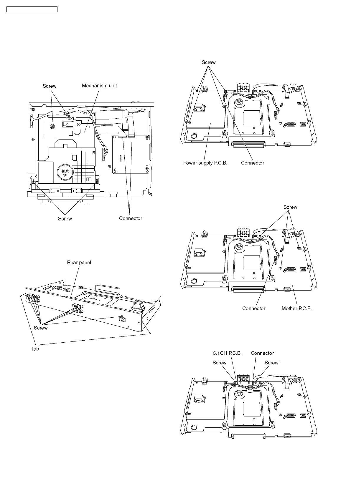
6.8. Mechanism Unit
1. Turn the gear jig clockwise to close the tray, turn until the
gear jig not to turn.
2. Unscrew the screws.
3. Remove the connectors.
4. Pull out the mechanism unit vertically.
6.10. Power supply P.C.B.
1. Unscrew the screws.
2. Remove the connector.
6.11. Mother P.C.B.
1. Unscrew the screws.
2. Remove the connector.
6.9. Rear panel
1. Unscrew the screws
2. Release the tabs.
6.12. 5.1CH P.C.B.
1. Remove the connector.
2. Unscrew the screws.
10
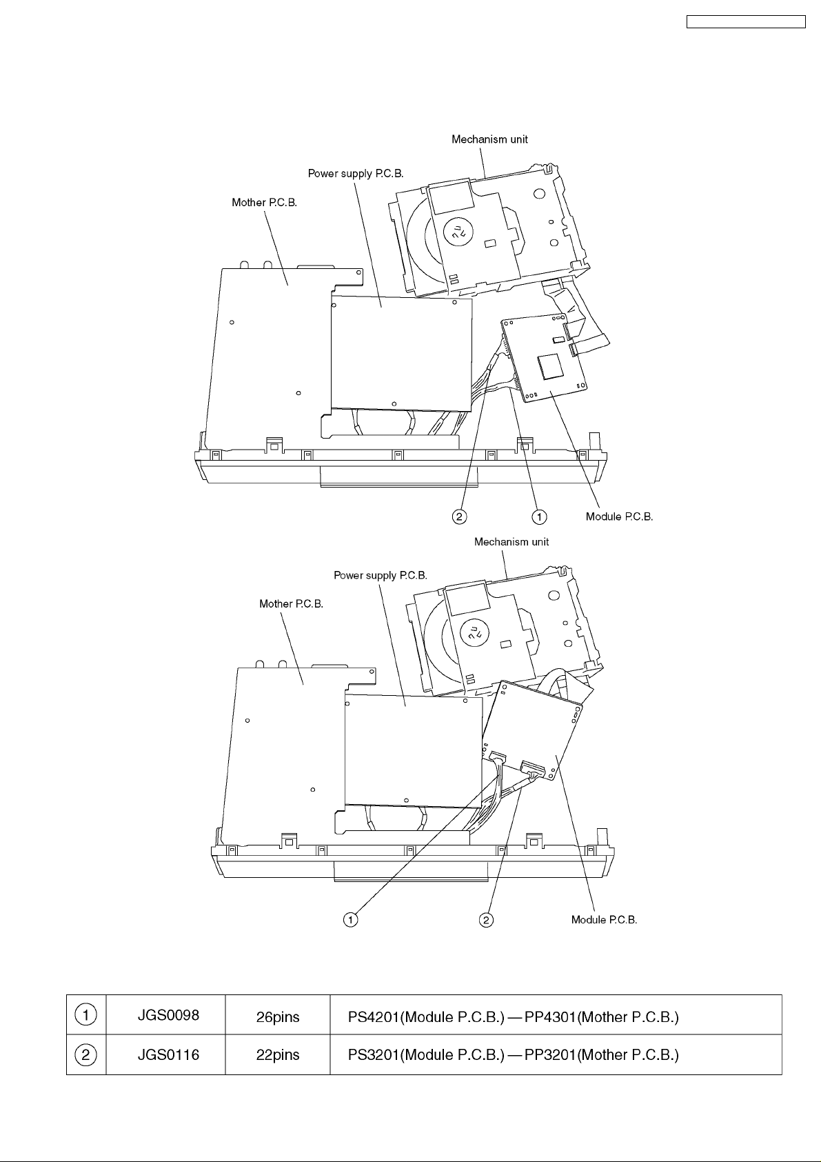
6.13. Service Position
6.13.1. Servicing position of the Module P.C.B.
DVD-K47GCS / DVD-K47GCU
6.13.2. List of the Extension Cables
11
DVD-K47GCS / DVD-K47GCU
7 ASSEMBLING AND
DISASSEMBLING THE
MECHANISM UNIT
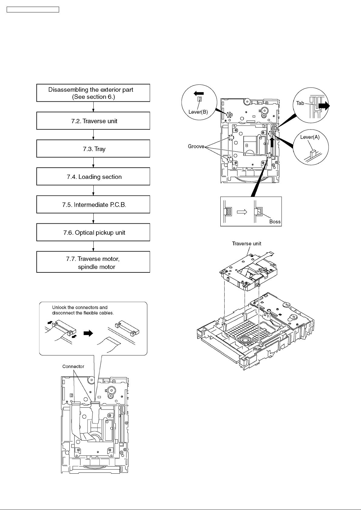
7.1. Disassembly Procedure
2. Slide the lever (A) in the arrow direction (to the opposite
side) till it stops.
3. Slide the lever (A) further by bending the tab at the right
side of the lever A in the right direction. (The right groove
opens and the boss becomes seen.)
4. Open the lever (B) to left. (The 2 grooves at the left side
open.)
7.2. Traverse Unit
1. Remove the connector.
5. Remove the traverse unit
12
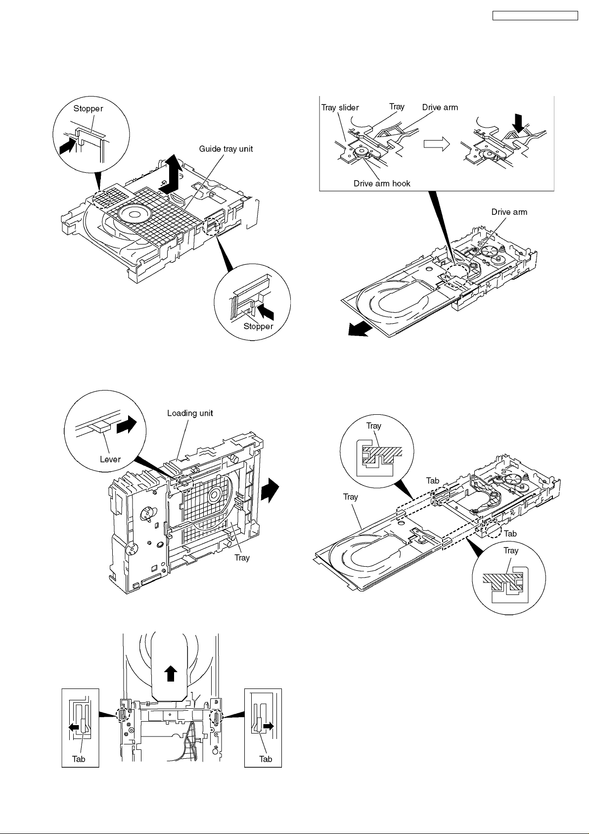
7.3. Tray
DVD-K47GCS / DVD-K47GCU
1. Slide the guide tray unit while pressing the stopper in the
arrow direction, and remove the guide tray unit.
2. Raise the loading unit.
3. Slide the lever in the arrow direction till it stops and pull the
tray out.
5. Remove the drive arm concave phase from the tray slider
and tray.
<Assembling the tray unit>
1. Insert a part of the tray into the unit sliding over the
groove on the mechanical chassis unit.
2. Insert the tray to the point before the tab of the
mechanical chassis unit.
4. Spread the tabs at the both sides and pull the tray out. (The
tray slides a little forward and stops.)
13
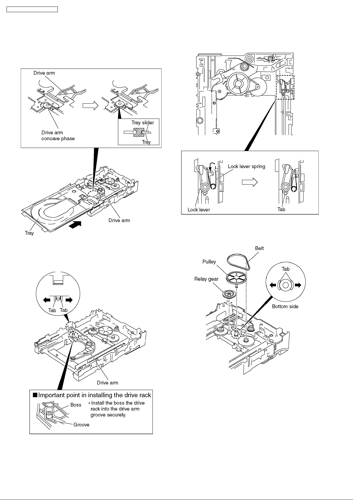
DVD-K47GCS / DVD-K47GCU
3. Hook the drive arm concave phase over the tray and the
tray slider.
4. Press in the tray.
5. Make sure that the tray and the drive arm move
smoothly.
2. Hook the lock lever spring on the lock lever projection part
temporarily.
3. Unlock the tab and remove the lock lever.
7.4. Loading section
1. Spread the tabs at the both sides and push out the drive
arm shaft.
4. Remove the belt.
5. Unlock the tab and remove the pulley.
6. Remove the relay gear.
14
DVD-K47GCS / DVD-K47GCU
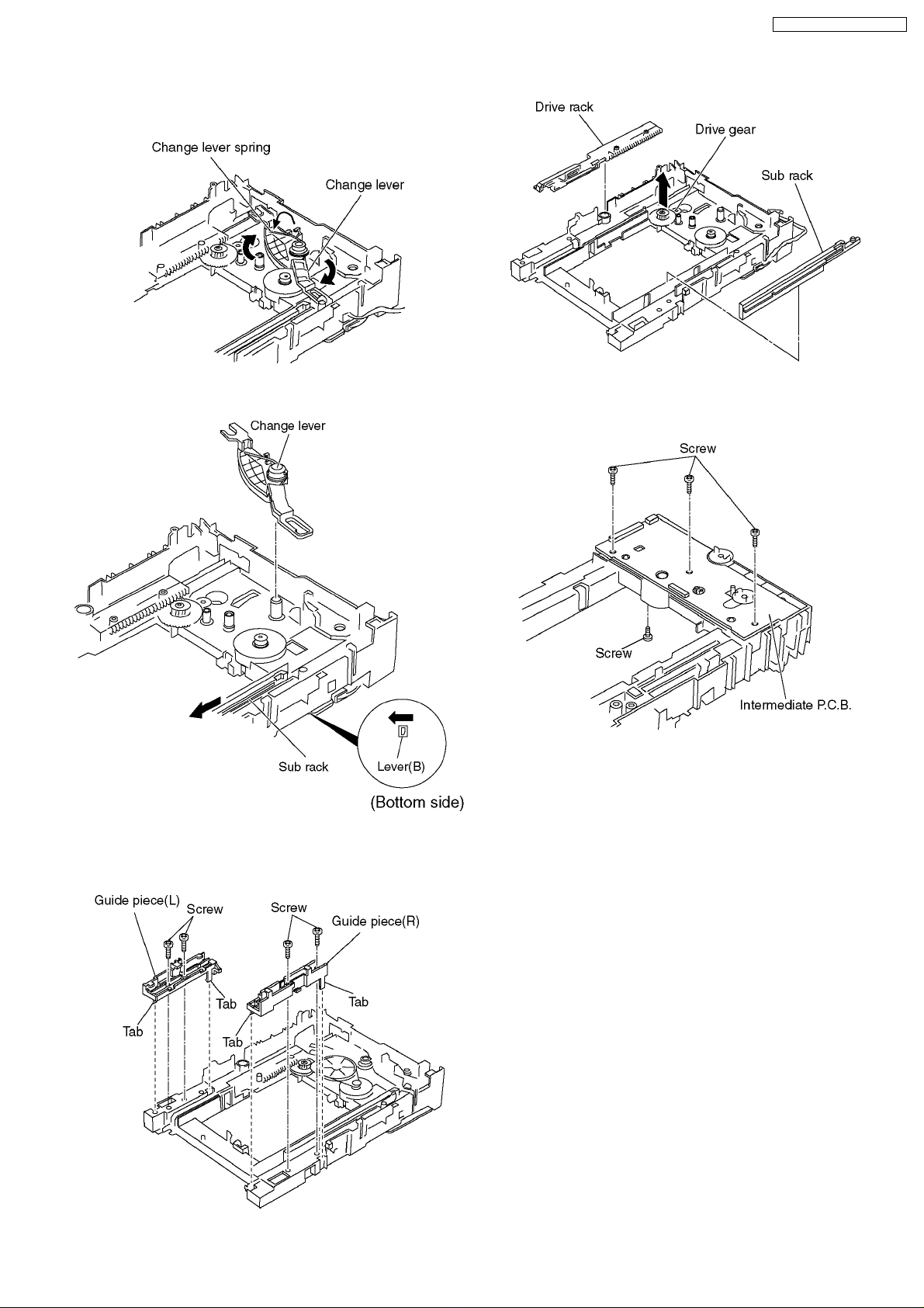
7. Turn the change lever in the arrow direction till it stops.
8. Hook the change lever spring on the change lever project
part temporarily.
9. Pull the lever (B) in the bottom sideto your side and remove
the change lever.
13. Remove the drive rack, the sub rack and the drive gear.
7.5. Intermediate P.C.B.
1. Unscrew the screws
10. Unscrew the screws.
11. Unlock the tabs and remove the guide piece (L).
12. Unlock the tabs and remove the guide piece (R).
15
DVD-K47GCS / DVD-K47GCU
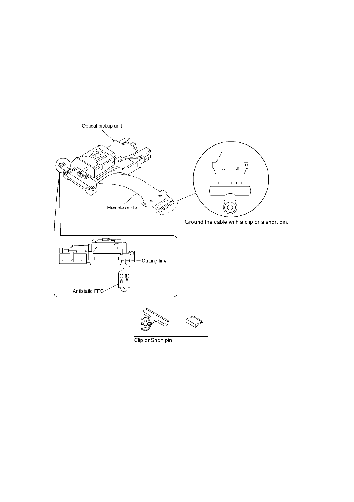
7.6. Optical Pickup Unit
7.6.1. Cautions to Be Taken in Handling the Optical Pickup Unit
The laser diode in the optical pickup unit may be damaged due to electrostatic discharge generating from clothes or human body.
Use due caution to electrostatic discharge damage when servicing the laser diode.
1. Do not give a considerable shock to the optical pickup unit as it has an extremely high-precise structure.
2. To prevent the laser diode from the electrostatic discharge damage, the flexible cable of the optical pickup unit removed from
the PCB should be short-circuited with a short pin or a clip.
3. The flexible cable may be cut off if an excessive force is applied to it. Use caution when handling the flexible cable.
4. The antistatic FPC is connected to the new optical pickup unit. After replacing the optical pickup unit and connecting the flexible
cable, cut off the antistatic FPC.
7.6.2. Cautions to Be Taken When Replacing the Optical Pickup
The flexible cable of the optical pickup unit which was supplied as a component is equipped with a short clip to prevent the laser
diode from being damaged due to electrostatic discharge. Remove the short clip before connecting the flexible cableand make sure
that the short land is open. (If the flexible cable is short-circuited, remove the solder.)
16
DVD-K47GCS / DVD-K47GCU
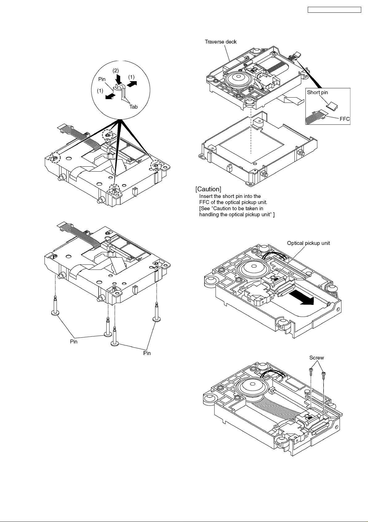
7.6.3. Procedure for Disassembling the
Optical Pickup Unit
1. Spread the tabs to push in the pin.
3. Remove the traverse deck.
2. Remove the pins.
4. Move the optical pickup unit in the arrow direction till it
stops.
5. Unscrew the screws.
17
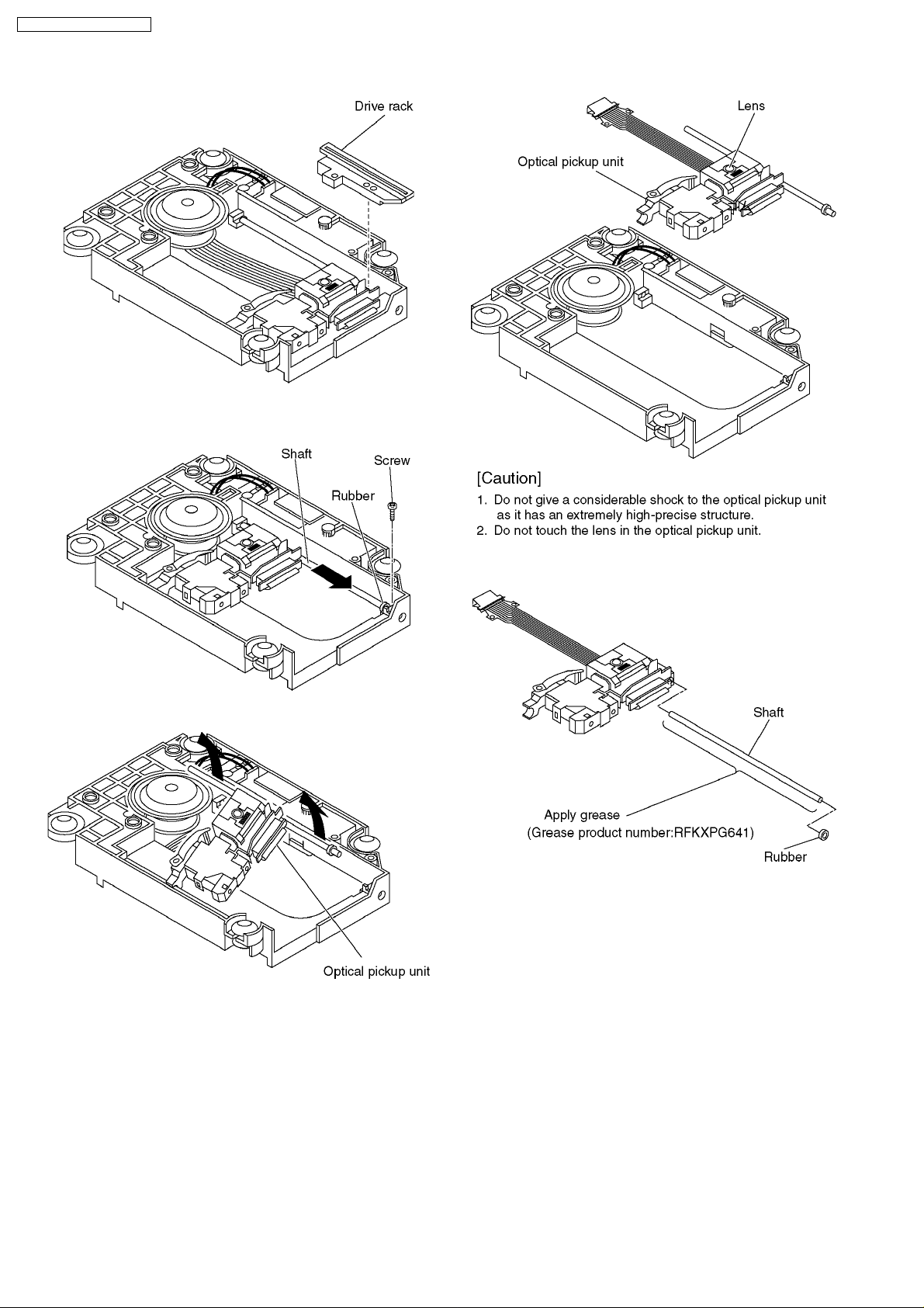
DVD-K47GCS / DVD-K47GCU
6. Remove the drive rack.
7. Unscrew the screw
8. Slide the shaft in the arrow direction.
10. Remove the optical pickup unit.
9. Lift the optical pickup unit with the shaft.
11. Pull the shaft and the rubber out.
18
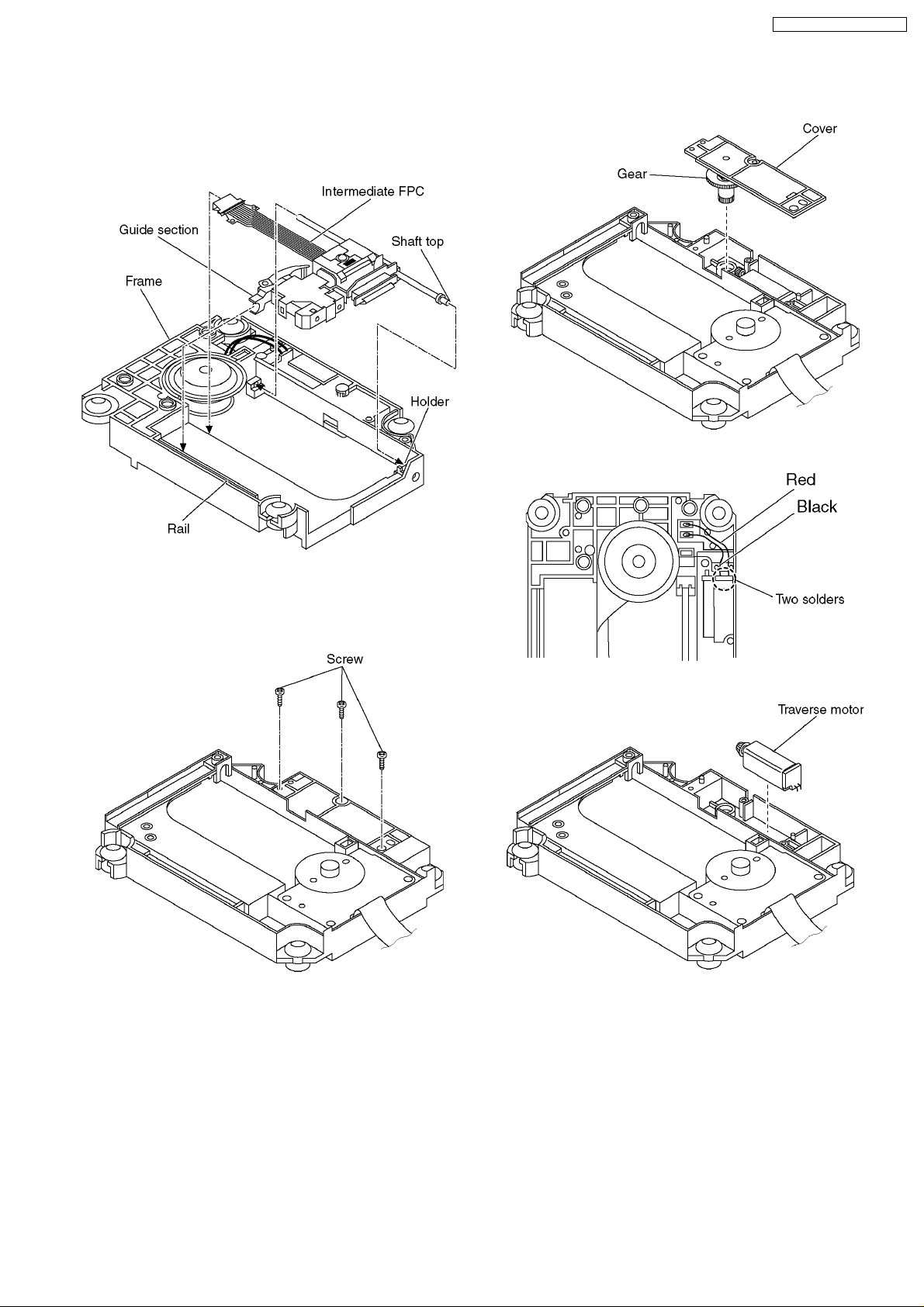
<Assembling the optical pickup unit>
1. Pass the intermediate FPC through the frame hole.
2. Align the guide section of the optical pickup unit with the
rail.
3. Install the shaft top to the holder.
DVD-K47GCS / DVD-K47GCU
2. Remove the cover while lifting the inner gear.
3. Remove the solders.
7.7. Traverse Motor and Spindle
Motor
1. Unscrew the screws.
4. Remove the traverse motor.
19
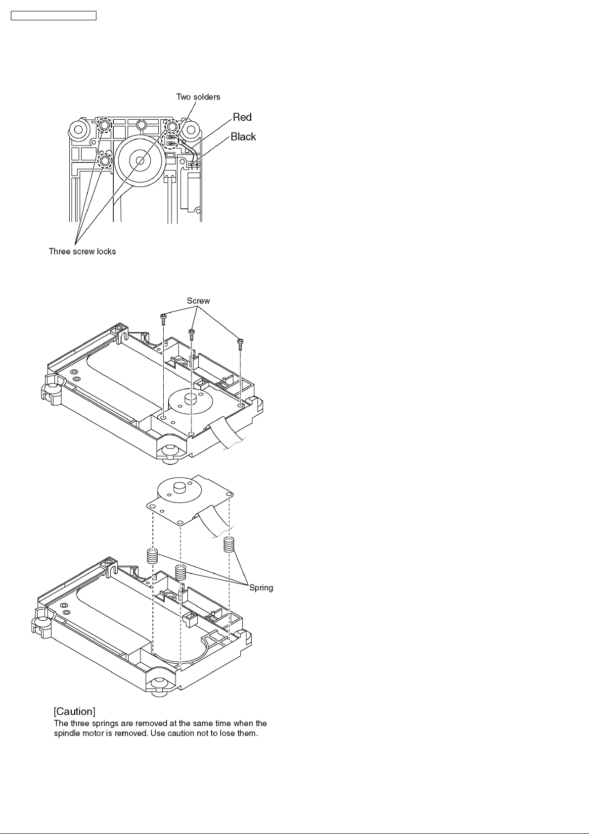
DVD-K47GCS / DVD-K47GCU
5. Remove the solders.
6. Remove the screw lock as carefully as you can.
7. Unscrew the screws with torx screw driver (T6).
8. Remove the spindle motor.
20
DVD-K47GCS / DVD-K47GCU
8 Self-Diagnosis Function and Service Modes
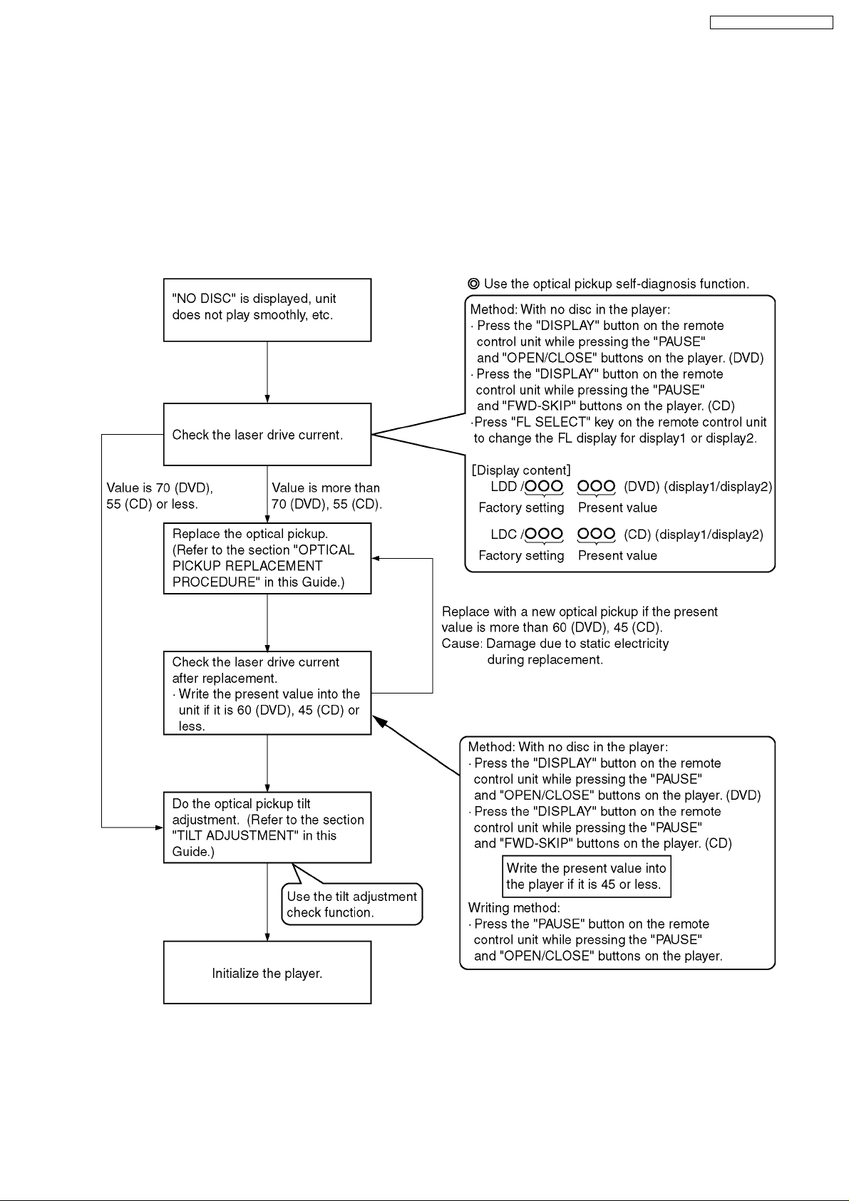
8.1. Optical Pickup Breakdown Diagnosis
The optical pickup self-diagnosis function and tilt adjustment check function have been included in this unit. When repairing, use
the following procedure for effective Self-diagnosis and tilt adjustment.Be sure to use the self-diagnosis functionbefore replacing
the optical pickup when "NO DISC" is displayed. As a guideline, you should replace the optical pickup when the value of the laser
drive current is more than 55.
Note:
Press the power button to turn on the power, and check the value within three minutes before the unit warms up. (Otherwise,
the result will be incorrect.)
21
DVD-K47GCS / DVD-K47GCU
8.2. Service Mode Table 1
The service modes can be activated by pressing various button combination on the player and remote control unit.
Player buttons Remote control unit buttons Application Note
PAUSE
+
OPEN/CLOSE
PAUSE
SKIP/SEARCH<<
OPEN/CLOSE
0 Displaying the UHF display F_ _ _ Refer to section 8.3. Self-
5 Jitter check, tilt adjustment
*Display shows J_xxx/yyy_zz
"yyy" and "zz" shown to the right have nothing to do with the jitter
value. "yyy" is the error counter, while "zz" isthe focus drive
value.
Refer to section 10.4. for Optical Pickup Tilt Adjustment
Procedure.
6 Checking the region numbers and broadcast system
7 Checking the program version Check the IC6301 FLASH
9 Lighting Confirmation Function of Display Tube
DISPLAY Checking the laser drive current Refer to section 7
PAUSE Writing the laser drive current value after replacing the optical
pickup (do not use for anything other than optical pickup
replacement)
Initializing the DVD player
(restoring factory preset settings)
Diagnosis Function (UHF
Display).
Refer to section 10.4.
Optical Pickup Tilt
Adjustment
ROM program.
Optical Pickup
Replacement Procedure.
Refer to section 8.5.
Initializing the DVD
player.
8.3. DVD Self Diagnostic Function-Error Code
Error Code Error Content Additional error explanation Defect 1 Defect 2 Defect 3 Defect 4
U, H error
U11 Focus error
U15 Unfinalized DVD-R
H01 Tray loading error
H02 Spindle servo error (Spindle servo, DV2 (IC8001) SP motor, CLV
H03 Traverse servo error
H04 Tracking servo error
H05 Seek error
H06 Power error Cannot switch off the power because of the panel
H07 Spindle motor drive
error
DSC related
F500 DSC error DV2 (IC8001) stops in the occurence of servo
F501 DSC not Ready DSC-system computer communication error
F502 DSC Time out error Similar disposal as F500 Optical
F503 DSC communication
Failure
F505 DSC Attention error Similar disposal as F500 Optical
F506 Invalid media Disc is flipped over, TOC unreadable,
ODC related
F600 Access failure to
management
information caused by
demodulation error
F601 Indeterminate sector ID
requested
F602 Access failure to LEAD-
IN caused by
demodulation error
F603 Access failure to
KEYDET caused by
demodulation error
F610 ODC abnormality No permission for command execution DV2
servo error)
and system computer communication error
error (starup, focus error, etc)
(Communication failure caused by idling of DSC)
Communication error (result error occured
although communication command was sent)
incompatible disc
Operation stopped because navigation data is not
accessible caused by the demodulation defect
Operation stopped caused by the request to
access abnormal ID data
LEAD IN data unreadable
Access failure to CSS data of disc
Spindle
motor ass’y
Optical
pickup
DV2
(IC8001)
pickup
DV2
(IC8001)
pickup
DISC DV2
DV2
(IC8001)
DV2
(IC8001)
(IC8001)
DV2
(IC8001)
DV2
(IC8001)
EEPROM
(IC8611)
DV2
(IC8001)
(IC8001)
servo drive
servo drive
servo drive
22
DVD-K47GCS / DVD-K47GCU
Error Code Error Content Additional error explanation Defect 1 Defect 2 Defect 3 Defect 4
F611 6626 QCODE don’t
read Error
F612 No CRC OK for a
specific time
F630 No reply to KEY DET
enquiry
F631 CPPM KEY DET is not
available till the FILE
terminal
F632 CPPM KEY DET is not
available
Disc code
F103 Illegal highlight Position Big possibility of disc specification violation during
HIC Error
F4FF Force initialize failure
(time out)
Micro computer error
F700 MBX overflow When replying message to disc manager
F701 Message command
does not end
F702 Message command
changes
F880 Task number is not
appropriate
F890 Sending message when
message is being sent
to AV task
F891 Message couldn’t be
sent to AV task
F893 FROM falsification FROM
F894 EEPROM abnormality EEPROM
F895 Language area
abnormality
F896 No existence model Firm version agreement check for factory preset
F897 Initialize is not
completed
F898 Disagreement of
hardware and software
F8A0 Message command is
not appropriate
Access failure to seek address in CD series DV2
Access failure to ID data in DVD series DV2
(for internal use only)
(CPPM file system is unreadable caused by
scratches)
Been revoked or falsified DISC EEPROM
highlight display
Next message is sent before replying to disc
manager
Message is changed before it is sent as a reply to
disc manager
Message coming from a non-existing task
Sending message to AV task
Begin sending message to AV task
Firm version agreement check for factory preset
setting failure prevention
setting failure prevention
Initialize completion check for factory preset
setting failure prevention
Unsuitable combination of AV DECORDER,
SDRAM and FLASH ROM (firmware)
Begin sending message to AV task
(IC8001)
(IC8001)
DISC CPPM
(IC8611)
DISC
EEPROM
(IC8611)
(IC8651)
(IC8611)
FROM
(IC8651)
(IC8001)
(IC8001)
communicat
ion on lone
(*1)
DV2
DV2
Serial
CPPM
(*1)
Note:
An error code will be canceled if a power supply is turned OFF.
*1: CPPM is the copy guard function beforehand written in the disk for protection of copyrights.
8.4. Last Error Code saved during NO PLAY
Error code Error Content System computer Setting task System computer internal error code
F0BF 6) Cannot playback because
physical layer is not recoginizable
F0C0 8) DVD: Cannot playback because it
is not DVD Video/Adio/VR
F0C1 9) DVD: Prohibited by the restricted
region code
F0C2 A) DVD: PAL restricted playback PCND_NOPLAY PAL 0x90 DiscManager 0xDOC2
F0C3 B) DVD: Parental lock setting
prohibits the playback of the entire
title
F0C4 C) VCD: Prohibited because it is in
PHOTO CD fromat
F0C5 VCD/CD: Prohibited because it is
CDROM without CD-DA
PCND_NOPLAY PHYSICAL
0x50
PCND_NOPLAY VIDEO 0x70 DiscManager 0xDOC0
PCND_NOPLAY RCD 0x80 DiscManager 0xDOC1
PCND_NOPLAY PTL 0xA0 DiscManager 0xDOC3
PCND_NOPLAY PHOTO CD
0xB0
PCND_NOPLAY CDROM 0xC0 DiscManager 0xDOC5
DriveManager 0xDOBF
DiscManager 0xDOC4
23
 Loading...