

Panasonic dmw-yagh Operation Manual
Owner’s Manual
Interface Unit
Model No.
Please read these instructions carefully before using this product,
and save this manual for future use.
DMW-YAGHPP
If you have any questions, visit:
USA : www.panasonic.com/support
PP
VQT5K48
CH0314TY0 -FJ
Read this first!
WARNING:
• To reduce the risk of fire, do not expose this equipment to rain or moisture.
• To reduce the risk of fire, keep this equipment away from all liquids. Use
and store only in locations which are not exposed to the risk of dripping
or splashing liquids, and do not place any liquid containers on top of the
equipment.
WARNING:
Always keep accessory (terminal cap) out of the reach of babies and small
children.
CAUTION:
Do not remove panel covers by unscrewing.
No user serviceable parts inside.
Refer servicing to qualified service personnel.
CAUTION:
In order to maintain adequate ventilation, do not install or place this unit in a
bookcase, built-in cabinet or any other confined space. To prevent risk of fire
hazard due to overheating, ensure that curtains and any other materials do
not obstruct the ventilation.
CAUTION:
To reduce the risk of fire and annoying interference, use the recommended
accessories only.
CAUTION:
Do not leave the unit in direct contact with the skin for long periods of time
when in use.
Low temperature burn injuries may be suffered if the high temperature parts of
this unit are in direct contact with the skin for long periods of time.
When using the equipment for long periods of time, make use of the tripod.
indicates safety information.
2
VQT5K48 (ENG)

Read this first! (continued)
CAUTION:
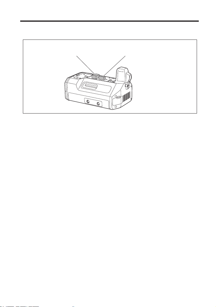
Do not lift the unit or the camera with a tripod attached.
The additional weight on the unit from the attached tripod may damage the
connection between the unit and the camera, and may result in injuries.
When a tripod is attached, always carry the equipment by the tripod.
indicates safety information.
The rating plate is on the underside of the unit.
(ENG) VQT5K48
3

Read this first! (continued)
FCC NOTICE (USA)
This device complies with part 15 of the FCC Rules.
Operation is subject to the following two conditions:
(1) This device may not cause harmful interference, and (2) this device must
accept any interference received, including interference that may cause
undesired operation.
CAUTION:
This equipment has been tested and found to comply with the limits for a
Class B digital device, pursuant to Part 15 of the FCC Rules. These limits
are designed to provide reasonable protection against harmful interference
in a residential installation. This equipment generates, uses and can radiate
radio frequency energy and, if not installed and used in accordance with
the instructions, may cause harmful interference to radio communications.
However, there is no guarantee that interference will not occur in a particular
installation. If this equipment does cause harmful interference to radio or
television reception, which can be determined by turning the equipment off
and on, the user is encouraged to try to correct the interference by one of the
following measures:
• Reorient or relocate the receiving antenna.
• Increase the separation between the equipment and receiver.
• Connect the equipment into an outlet on a circuit different from that to which
the receiver is connected.
• Consult the dealer or an experienced radio/TV technician for help.
The user may find the booklet “Something About Interference” available from
FCC local regional offices helpful.
FCC Warning:
To assure continued FCC emission limit compliance, follow the attached
installation instructions and the user must use only shielded interface cables
when connecting to host computer or peripheral devices.
Also, any unauthorized changes or modifications to this equipment could void
the user’s authority to operate this device.
indicates safety information.
4
VQT5K48 (ENG)

The unit is exclusively for Panasonic DMC-GH4 digital camera.
Mounting the unit to a digital camera allows you to output 4K, 3G-SDI, and HD-SDI compatible
video from the SDI terminal and perform video production with higher-quality video.
Two-channel audio input (XLR) is supported with audio level meters available.
You can also input an external timecode to be used as a reference signal.
When the unit is mounted on a digital camera, the electronic sound and electronic shutter
sound of the digital camera are disabled.
Contents
Read this first! ...............................................2
Accessories ...................................................7
Names and Functions of Components ........8
Mounting to the Digital Camera .................10
Switching the Video Output ........................11
Additional Menus .........................................12
Specifications ..............................................14
Limited Warranty (ONLY FOR U.S.A.) ........15
(ENG) VQT5K48
5

Handling the unit
The unit is not splash proof or dust proof.
Be careful not to allow sand, dust, or water to adhere or enter into the terminal area, digital
camera, or this unit when attaching or removing this unit.
This unit is not waterproof, so it cannot be used underwater.
Do not subject the unit to strong shocks or vibration. Doing so may result in malfunction or
damage.
When the unit is mounted on the digital camera, do not use the shoulder strap supplied with the
digital camera. Always hold both the digital camera and the unit while carrying.
Keep the unit away from insecticide sprays and other volatile substances.
If the unit is exposed to these sprays or substances, its external case may deteriorate and/or its
paint may come off.
Do not leave the unit in contact with any items made of rubber or PVC for prolonged periods of
time.
Under no circumstances should the unit be used or stored in any of the following locations
since doing so may cause trouble in operation or malfunctioning:
• In direct sunlight or on a beach in summer
• In locations with high temperatures and humidity
levels or where changes in temperature and
humidity are acute
• Where there is fire
Please also read the manual of your digital camera.
Panasonic will not be liable for any direct or indirect damages or losses resulting from
operation or malfunction of this product.
The design and specifications found in this document are subject to change without notice
and may differ from the actual product.
If the unit’s fan stops due to a malfunction or error and you continue to operate the unit, video
output may not be performed properly.
• Near heaters, air conditioners or
humidifiers
• Where there is vibration
• Inside a vehicle
Cleaning
When cleaning, wipe the unit with a dry soft cloth.
When the unit is soiled badly, it can be cleaned by wiping the dirt off with a well-wrung wet
cloth, and then with a dry cloth.
Do not use solvents such as benzine, thinner, alcohol, kitchen detergents, etc., to clean the
unit, since they may deteriorate the external case or the coating may come off.
When using a chemical cloth, be sure to follow the accompanying instructions.
6
VQT5K48 (ENG)
Accessories
Be sure to dispose of the packaging materials in an appropriate manner after unpacking the
unit.
The following supplied accessories come attached to the unit.
Terminal cap
(electrical contacts)
Terminal cap
(interface contacts)
(ENG) VQT5K48
7
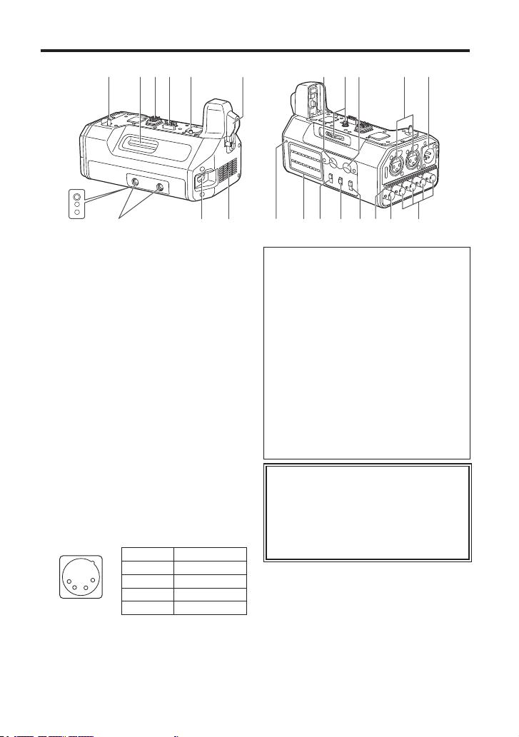
Names and Functions of Components
4 18 2 3 4 5 14141
1 HDMI connection terminal
Connects to the digital camera’s HDMI
connector.
2 Electrical contacts
3 Interface contacts
4 Camera attachment pins
5 Attachment screw
6 Screw hole (1/4-20 UNC)
Attaches to PL lens compatibility adapters,
etc.
7 HDMI terminal
HDMI Type A output terminal.
(VIERA Link is not supported.)
Use a high-speed double-shielded
4K-compatible HDMI cable (up to 2 m)
that is marked with the HDMI logo when
connecting to this terminal.
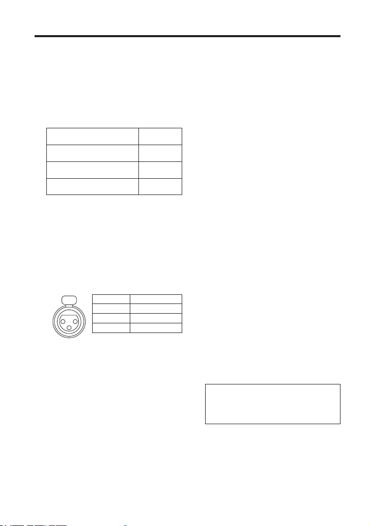
8 DC IN terminal
Connects to the DC power supply (battery:
12 V DC).
1
2
3
4
Pin no. Signal
1 GND
2, 3 —
4 12 V
CASE Frame GND
11
8
1812131216 157 19617
Notes on DC power supply (battery)
Verify that the output voltage matches the
unit’s voltage rating before connection.
Use a rated output current that is equal
to or higher than the unit’s input current
rating.
Use a shielded cable that is less than 2 m
in length for the DC cable connecting the
unit to the DC power supply (battery).
An inrush current is generated when the
digital camera is turned on. An insufficient
power supply capacity when the power is
turned on may result in malfunction. We
recommend using a DC power supply
(battery) that can provide at least twice the
power consumption value of the unit.
Verify the pin positions of the output
connector of the DC power supply
(battery) and the unit’s DC IN terminal,
and be sure to connect with the correct
polarities.
Connecting +12 V power to the GND
terminal may result in fire or malfunction.
109
8
VQT5K48 (ENG)
Names and Functions of Components (continued)
9 TC IN terminal (BNC)
Timecodes are input here.
Input a reference timecode to this terminal
to synchronize the digital camera’s
timecode to that of external equipment.
Use a 5C-FB equivalent double-shielded
cable to connect to this terminal.
10 SDI OUT [1, 2, 3, 4] terminals (BNC)
Terminals reserved for SDI output.
Resolution setting
C4K, 4K
<1.5G-SDI Square Division>
FHD (1080/59.94p, 1080/50p)
<3G-SDI>
FHD (Other than the above), HD
<1.5G-SDI>
Use a 5C-FB equivalent double-shielded
cable to connect to this terminal.
When outputting videos that do not
include timecodes (e.g., when [Rec
Format] is set to [MP4] on the digital
camera), a timecode will not be output.
Output
terminal
1 to 4
1, 2
(same signal)
1 to 4
(same signal)
11 AUDIO IN [CH1, CH2] terminals
(XLR, 3-pin)
Connects to audio equipment or
microphones.
PUSH
2
3
Pin no. Signal
1
1 GND
2 AUDIO IN (H)
3 AUDIO IN (C)
12 LINE / MIC / +48V switches
Switch these based on the audio
equipment connected to the AUDIO IN
CH1 or AUDIO IN CH2 terminal.
LINE:
When line input audio equipment is
connected. (Input level: 0 dBu)
MIC:
When an external microphone is
connected.
(Input level:
+48V:
When a phantom microphone (a
microphone that requires a +48 V power
supply) is connected.
-
50 dBu)
A power supply of +48 V will be
provided to the AUDIO IN CH1 and
AUDIO IN CH2 terminals.
13 STEREO / MONO switch
Switches the audio that is input to the
AUDIO IN CH1 and AUDIO IN CH2
terminals to stereo or monaural audio.
STEREO:
Two-channel stereo audio.
MONO:
Monaural audio.
The audio that is input to the AUDIO
IN CH1 terminal will also be input to
AUDIO IN CH2.
14 REC LEVEL dials
Adjust the audio inputs to the AUDIO
IN CH1 and AUDIO IN CH2 terminals
individually.
15 Level meters
Display individual indicators for the audio
input levels of the AUDIO IN CH1 and
AUDIO IN CH2 terminals.
The indicators light red when the audio
levels exceed 0 dB.
Adjust the REC LEVEL dials (
prevent the audio levels from exceeding
0 dB.
16 Power indicator
Lights when the connected digital camera
is turned on.
17 Tripod attachment holes
Compatible with 1/4-20 UNC and 3/8-16
UNC screws.
Use the appropriate hole according to the
diameter of the tripod screw.
The holes have a depth of 5.5 mm.
When attaching a tripod to the unit, do
not tighten the screw with excessive
force.
18 Intake vent
19 Exhaust vent
14) to
(ENG) VQT5K48
9
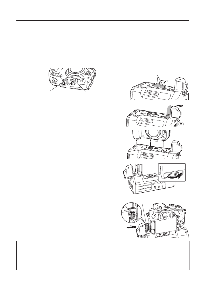
Mounting to the Digital Camera
Make sure that a DC power supply is not connected to the unit’s DC IN terminal and that the
digital camera is turned off.
(Mounting or dismounting while the power is on may result in malfunction.)
1 Remove the cover for the battery grip connector and cover for the interface unit
connector on the digital camera, and remove the electrical contact and interface
contact caps on the unit.
Store the connector covers and contact caps safely to avoid loss.
To protect the terminals, reattach the covers and caps after you finish using the unit.
Terminal caps
Cover for the battery grip
connector
Cover for the interface unit
connector
2 Loosen the HDMI connection terminal screw (A),
and slide the HDMI connection terminal out to the
side.
Do not twist or pull the HDMI connection terminal with
excessive force. Doing so may result in malfunction
or damage.
3 Align the attachment screw, contacts, and camera
attachment pins, and attach the digital camera.
4 Rotate the attachment screw (B) in the direction of
the arrow and tighten it securely.
Verify that the attachment screw is tightened securely
during use.
Terminal cover
5 Open the terminal cover on the digital camera, slide
the HDMI connection terminal on the unit inward
(toward the camera) to connect it, and tighten the
HDMI connection terminal screw (A) securely.
Open the terminal cover on the digital camera 90
degrees, and store it in the HDMI connection terminal.
Dismounting from the digital camera
Make sure that a DC power supply is not connected to the unit’s DC IN terminal and that
the digital camera is turned off, and then perform the mounting procedure in reverse order
(disconnect the HDMI connection terminal before rotating the attachment screw (B)).
Performing the procedure in the incorrect order may result in damage.
10
VQT5K48 (ENG)
90°
(A)
(B)
 Loading...