

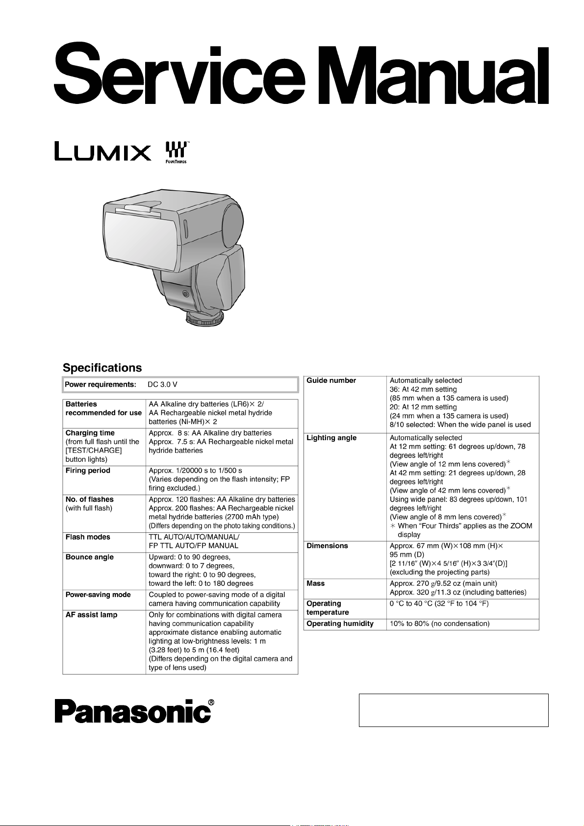
Panasonic DMW-FL360, DMW-FL360PP, DMW-FL360E, DMW-FL360GK Service Manual
ORDER NO. DSC0609033CE
Model No.DMW-FL360PP
DMW-FL360E
DMW-FL360GK
B26
Flash
© 2007 Matsushita Electric Industrial Co., Ltd. All
rights reserved. Unauthorized copying and
distribution is a violation of law.
DMW-FL360PP / DMW-FL360E / DMW-FL360GK
CONTENTS
Page Page
1 INTRODUCTION 3
1.1. INTRODUCTION
1.2. IMPORTANT NOTICE
2 SAFETY PRECAUTIONS
2.1. GENERAL GUIDELINES
2.2. LEAKAGE CURRENT COLD CHECK
2.3. LEAKAGE CURRENT HOT CHECK (See Figure 1.)
3 OPERATING GUIDE
4 OPERATING INFORMATION
5 HOW TO DISCHARGE THE FLASH CHARGING CAPACITOR
6 SERVICE FIXTURE & TOOLS
6.1. SERVICE FIXTURE & TOOLS
7 ELECTRICAL ADJUSTMENT
3
3
4
4
4
4
5
7
16
17
17
7.1. AFTER REPLACING
8 DISASSEMBLY AND ASSEMBLY INSTRUCTIONS
8.1. DISASSEMBLY FLOW CHART
8.2. PCB LOCATION
8.3. DISASSEMBLY PROCEDURE
9 WIRING CONNECTION DIAGRAM
10 EXPLODED VIEWS
10.1. FRAME & CASING SECTION
10.2. PACKING PARTS & ACCESSORIES SECTION
11 REPLACEMENT PARTS LIST
11.1. MECHANICAL REPLACEMENT PARTS LIST
18
18
19
19
19
20
27
29
29
30
30
30
2

DMW-FL360PP / DMW-FL360E / DMW-FL360GK
1 INTRODUCTION
1.1. INTRODUCTION
This service manual contains technical information, which allow service personnel’s to understand and service this model.
Please place orders using the parts list and not the drawing reference numbers.
If the circuit is changed or modified , the information will be followed by service manual to be controlled with original service manual.
1.2. IMPORTANT NOTICE
1. The Electric components on the PCB (Printed Circuit Boad) are not supplied.
There fore, this Service Manual does not contain the PCB Layout, Schematic Diagram and replamenent parts list for Electric
components on the P.C.B.s.
2. Also, please confirm the following notice for replacement parts.
a. The "CPU P.C.B." is supplied as "REAR CASE UNIT".
b. The "HOT SHOE P.C.B." is supplied as "HOT SHOE UNIT".
c. The "BOUNCE (V) P.C.B." includes "BOUNCE (H) P.C.B.".
3
DMW-FL360PP / DMW-FL360E / DMW-FL360GK
2 SAFETY PRECAUTIONS
2.1. GENERAL GUIDELINES
1. IMPORTANT SAFETY NOTICE
There are special compon ents used in this equipment
which are important for safety. These parts are marked by
in the Schematic Diagrams, Circuit Board Layout,
Exploded Views and Replacement Parts List. It is essential
that these critical parts should be replaced with
manufacturer’s specified parts to prevent X-RADIATION,
shock, fire, or other hazards. Do not modify the original
design without permission of manufacturer.
2. An Isolation Transformer should always be used during the
servicing of AC Adaptor whose chassis is not isolated from
the AC power line. Use a transformer of adequate power
rating as this protects the technician from accidents
resulting in personal injury from electrical shocks. It will also
protect AC Adaptor from being damaged by accidental
shorting that may occur during servicing.
3. When servicing, observe the original lead dress. If a short
circuit is found, replace all parts which have been
overheated or damaged by the short circuit.
4. After servicing, see to it that all the protective devices such
as insulation barriers, insulation papers shields are properly
installed.
5. After servicing, make the following leakage current checks
to prevent the customer from being exposed to shock
hazards.
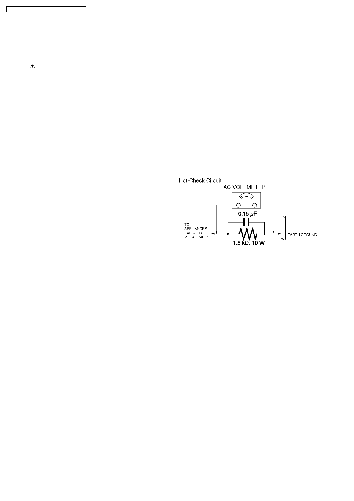
2.3. LEAKAGE CURRENT HOT
CHECK (See Figure 1.)
1. Plug the AC cord directly into the AC outlet. Do not use an
isolation transformer for this check.
2. Connect a 1.5 kΩ, 10 W resistor, in parallel with a 0.15 µF
capacitor, between each exposed metallic part on the set
and a good earth ground, as shown in Figure 1.
3. Use an AC voltmeter, with 1 kΩ/V or more sensitivity, to
measure the potential across the resistor.
4. Check each exposed metallic part, and measure the
voltage at each point.
5. Reverse the AC plug in the AC outlet and repeat each of the
above measure ments.
6. The potential at any point should not exceed 0.75 V RMS.
A leakage current tester (Simpso n Model 229 or equivalent)
may be used to make the hot checks, leakage current must
not exceed 1/2 mA. In case a measurement is outside of
the limits specified, there is a possibility of a shock hazard,
and the equipment should be repaired and rechecked
before it is returned to the customer.
2.2. LEAKAGE CURRENT COLD
CHECK
1. Unplug the AC cord and connect a jumper between the two
prongs on the plug.
2. Measure the resistance value, with an ohmmeter, between
the jumpere d AC plug and each exposed metallic cabinet
part on the equipment such as screwheads, connectors,
control shafts, etc. When the exposed metallic part has a
return path to the chassis, the reading should be between 1
MΩ and 5.2 MΩ. When the exposed metal does not have a
return path to the chassis, the reading must be infinity.
Figure. 1
4
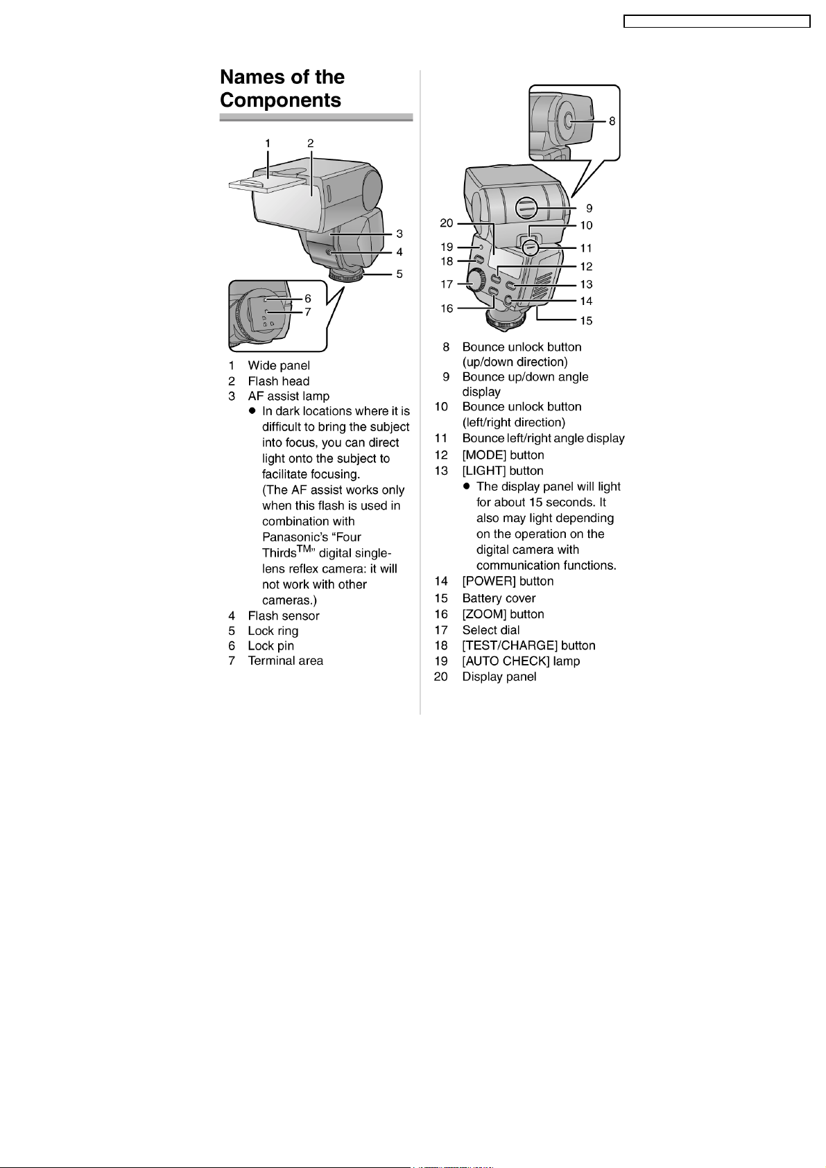
3 OPERATING GUIDE
DMW-FL360PP / DMW-FL360E / DMW-FL360GK
5
DMW-FL360PP / DMW-FL360E / DMW-FL360GK
6
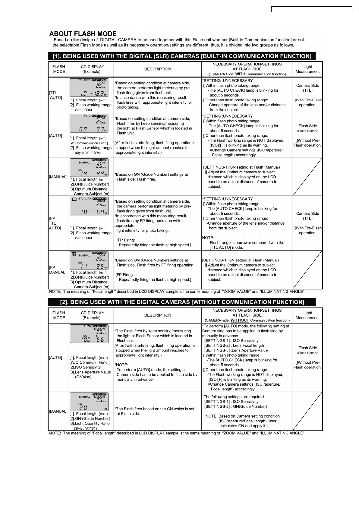
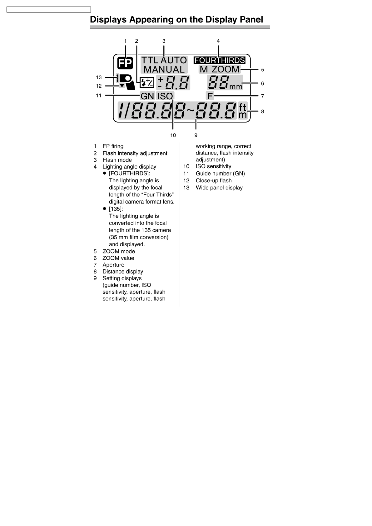
4 OPERATING INFORMATION
DMW-FL360PP / DMW-FL360E / DMW-FL360GK
7
DMW-FL360PP / DMW-FL360E / DMW-FL360GK
8
DMW-FL360PP / DMW-FL360E / DMW-FL360GK
9
DMW-FL360PP / DMW-FL360E / DMW-FL360GK
10
 Loading...