

Page 1
Panasonic
Operating Instructions
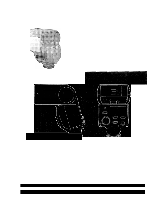
Flash
Model No.
LuMix ■
Before connecting, operating or
adjusting this product, please read the
Instructions completely.
For USA assistance, please call: 1-800-272-7033 or send e-mail to : digitalstillcam@us.panasonic.com
For Canadian assistance, please call: 1-800-561-5505 or visit us at www.panasonic.ca
DMW-FL360
W
FourThirds
VQT1B10
Page 2

Contents
Information for Your Safety
Precautions...................................................................................................6
Supplied accessories ........................................................................................ 7
Names of the Components ................................................................................7
Displays Appearing on the Display Panel .........................................................9
.....
.................................................................... 3
Concerning the batteries
Inserting and Removing the Unit’s Batteries (optional) ...................................15
Checking the Flash’s Remaining Battery Charge
Mounting the Unit onto the Digital Camera, and Removing it .........................17
Taking Pictures using a Digital Camera with Communication
Functions
Taking Pictures using a Digital Camera without Communication
Functions....................................................................................................... 28
Other Applications
Functions ....................................................................................................... 39
Concerning Continuous Firing..........................................................................42
Table of Guide Numbers (GN) .........................................................................43
Troubleshooting ...............................................................................................46
Cautions for Use ..............................................................................................48
Specifications................................................................................................... 50
Limited Warranty...............................................................................................52
Spanish Quick Use Guide/Guia rápida en español..........................................57
.................................................................................................... 19
How to select the flash mode
[TTLAUTO] ................................................................................................21
[AUTO]...................................................................................................... 22
[MANUAL]...................................................................................................23
[FP TTLAUTO].......................................................................................... 24
[FP MANUAL] ............................................................................................25
How to select the flash mode
[AUTO]........................................................................................................29
[MANUAL]
Taking pictures with bounce lighting...........................................................34
Taking pictures at close range....................................................................35
Selecting the lighting angle manually ........................................................36
How to use the Wide Panel .......................................................................37
Many choices for different flash photography applications
.................................................................................................
.................................................................................
...........................................
....................................................................
......
..............................................................28
...
...................................................................................... 34
........................
10
16
19
.32
38
2
VQT1B10
Page 3

Information for Your Safety
IMPORTANT SAFETY INSTRUCTIONS
When using your photographic equipment, basic
safety precautions should always be followed,
including the following:
e Read and understand all instructions before using.
• Close supervision is necessary when any appliance
is used by or near children. Do not leave appliance
unattended while in use.
• Care must be taken as burns can occur from
touching hot parts.
® Do not operate if the appliance has been dropped or
damaged - until it has been examined by qualified
service personnel.
• Let appliance cool completely before putting away.
• To reduce the risk of electric shock, do not immerse
this appliance in water or other liquids.
» To reduce the risk of electric shock, do not
disassemble this appliance, but take it to qualified
service personnel when service or repair work is
required. Incorrect reassembly can cause electric
shock when the appliance is used subsequently.
• The use of an accessory attachment not
recommended by the manufacturer may cause a risk
of fire, electric shock, or injury to persons.
SAVE THESE
INSTRUCTIONS
3
VOTI BIO
Page 4

FCC Note: (U.S. only)
This equipment has been tested and found to comply with the limits
for a Class B digital device, pursuant to Part 15 of the FCC Rules.
These limits are designed to provide reasonable protection against
harmful interference in a residential installation. This equipment
generates, uses, and can radiate radio frequency energy and, if not
installed and used in accordance with the instructions, may cause
harmful interference to radio communications. However, there is no
guarantee that interference will not occur in a particular installation. If
this equipment does cause harmful interference to radio or television
reception, which can be determined by turning the equipment off and
on, the user is encouraged to try to correct the interference by one or
more of the following measures:
• Reorient or relocate the receiving antenna.
• Increase the separation between the equipment and receiver.
• Connect the equipment into an outlet on a circuit different from that
to which the receiver is connected.
• Consult the dealer or an experienced radio/TV technician for help.
FCC Caution: To assure continued compliance, follow the
attached installation instructions.
Any changes or modifications not expressly approved by the party
responsible for compliance could void the user’s authority to operate
this equipment.
This device complies with Part 15 of the FCC Rules. Operation is
subject to the following two conditions: (1) This device may not cause
harmful interference, and (2) this device must accept any interference
received, including interference thaf may cause undesired operation.
(Canada only)
This Class B digital apparatus complies with Canadian ICES-003.
4
VOTI BIO
Page 5
i This flash is designed to be
used with digital cameras made
by Panasonic.
It is compatible with DMC-FZ50,
DMC-L1K (with communication
functions: PI 9 to 27),
DMC-FZ30 etc. (without
communication functions: P28 to
33). (as of September 2006)
» The digital camera illustrations
in these operating instructions
show DMC-FZ50 as an
example.
» Four Thirds™ is a trademark.
WARNING
TO REDUCE THE RISK OF
FIRE OR SHOCK HAZARD
AND ANNOYING
INTERFERENCE, USE ONLY
THE RECOMMENDED
ACCESSORIES AND DO NOT
EXPOSE THIS EQUIPMENT
TO RAIN, MOISTURE,
DRIPPING OR SPLASHING.
DO NOT REMOVE THE
COVER (OR BACK); THERE
ARE NO USER
SERVICEABLE PARTS
INSIDE. REFER SERVICING
TO QUALIFIED SERVICE
PERSONNEL.
-If you see this symbol-
information on Disposai in
other Countries outside the
European Union
This symbol is only valid in the
European Union.
If you wish to discard this
product, please contact your
local authorities or dealer and
ask for the correct method of
disposal.
VOTI BIO
5
Page 6

■ Handling the unit
• Do not subject the unit to
strong vibration or impact.
Doing so may cause not only the
unit to malfunction but also the
flash head to break.
• Before carrying the unit around
with you, ensure that the wide
panel is properly retracted.
(P37)
• Sand and dirt may cause the
unit to malfunction. When
using the unit in an
environment such as a beach,
take steps to protect it from
sand and dirt.
• When taking photos on rainy
days or on a beach, take care to
keep the unit dry.
• The unit is not waterproof. If
rain or drops of water splash
onto the unit, wipe off the
water with a dry cloth. If the
unit does not operate
normally, consult the dealer or
your nearest servicenter.
• Read the operating instructions
for your digital camera.
I When the unit is not going to
be used for a prolonged
period
Be absolutely sure to remove
the batteries from the unit.
If the batteries are left inside the
unit, a faint current will flow
continuously, even when the
unit’s power is off, gradually
discharging the batteries. (For
details on nickel metal hydride
batteries, refer to P13.)
Store the batteries in a cool,
moisture-free location where the
temperature is kept as constant
as possible.
[Recommended temperature
range: 15 °C to 25 °C
(59°Fto 77 T);
recommended humidity range:
40% to 60%]
If you plan to store the unit and/
or its batteries inside a closet or
cupboard, it is recommended
that you put a desiccant (silica
gel) in with them.
6
VQT1B10
Page 7
Supplied
accessories
[Inspection to be performed
when you unpack the unit]
When removing the unit from its
packing box, check that the main
unit and its supplied accessory is
there and also check their external
appearance and functions to verify
that they have not sustained any
damage during distribution and
transportation.
If you discover any trouble, contact
your vendor before using the
product.
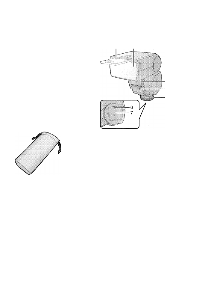
For this flash, use only the flash
case shown below.
Flash case
VFC4230
® The batteries are optional.
Names of the
Components
1 Wide panel (P37)
2 Flash head
3 AF assist lamp (P40)
• In dark locations where it is
difficult to bring the subject
into focus, you can direct
light onto the subject to
facilitate focusing.
(The AF assist works only
when this flash is used in
combination with
Panasonic’s “Four
Thirds™” digital single
lens reflex camera: it will
not work with other
cameras.)
4 Flash sensor
5 Lock ring (P17)
6 Lock pin (P17)
7 Terminal area (P17)
VQT1B10
7
Page 8
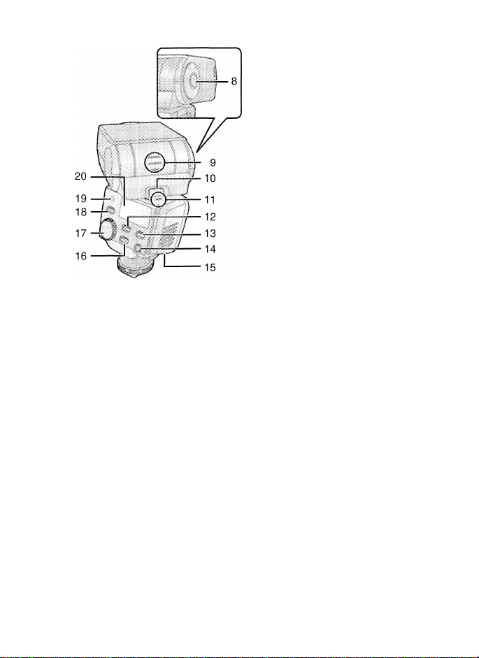
18 [TEST/CHARG E] button
(P16, 19, 28)
19 [AUTO CHECK] lamp
(P16, 21,22, 24, 29)
20 Display panel (P9)
8
VQT1B10
Bounce unlock button
(up/down direction) (PI7,
Bounce up/down angle
display (P34)
10
Bounce unlock button
(left/right direction) (PI7, 34)
Bounce left/right angle display
11
(P34)
12
[MODE] button (PI 9, 28, 39)
[LIGHT] button
13
® The display panel will light
for about 15 seconds. It
also may light depending
on the operation on the
digital camera with
communication functions.
14
[POWER] button
(PI 6, 19, 28, 39)
15
Battery cover (PI 5)
16
[ZOOM] button
(P29, 32, 36, 37)
17
Select dial
(P23, 26, 29, 32, 39)
34)
Page 9

Displays Appearing on the Display Panel
1 i
1
TTLAUTO
ob
MANUAL
13 —
12 —
11 —
FP firing (P24, 25)
Flash intensity adjustment
(P26)
Flash mode (PI 9, 28)
Lighting angle display (P40)
® [FOURTHIRDS]:
The lighting angle is
displayed by the focal
length of the “Four Thirds”
digital camera format lens.
® [135]:
The lighting angle is
converted into the focal
length of the 135 camera
(35 mm film conversion)
and displayed.
ZOOM mode (P36)
ZOOM value (P36)
Aperture
Distance display (P40)
Setting displays
(guide number, ISO
sensitivity, aperture, flash
//
-GN ISO
I
'I o
Iff
3
1
4- O O
- U.U
I.
Li
10
4
1
agwEi'iiiiaiH
M ZOOM-
IDOIIIIIL
LI Li mm
p
---------
o
O O O ft
■liU.Lllli
working range, correct
distance, flash intensity
adjustment)
10 ISO sensitivity
11 Guide number (GN) (P43)
12 Close-up flash (P35)
13 Wide panel display (P37)
---
9
VQT1B10
Page 10

Concerning the batteries
M Types of batteries that can be
used
AA Alkaline dry batteries (LR6)
AA Rechargeable nickel metal
hydride batteries (Ni-MH)
The use of batteries made by
Panasonic is recommended.
The performance of the
batteries used may significantly
differ depending on which
battery brand is used, how long
the batteries have been stored
since they were manufactured
and how they have been stored.
The performance of the
batteries decreases temporarily
at low temperatures [below
10 °C (50 °F)], but will be
restored when the temperature
returns to room temperature.
Malfunctioning may occur under
certain ambient temperatures
and operating conditions.
However, this is not indicative of
trouble.
In order to ensure that the
batteries will function for as long
as possible, it is recommended
that you turn off the unit’s power
during the intervals between
taking photos. If the unit is to be
used for prolonged periods, the
use of rechargeable nickel metal
hydride batteries is
recommended.
® Once spent, batteries may
recover their performance when
left standing for a while, but they
will quickly become unusable
again. For this reason, always
make a point of replacing spent
batteries with fresh ones.
■ Types of batteries with which
operation is not guaranteed
AA Ni-Cd batteries
AA Nickel-manganese batteries
(ZR6)
AA Lithium batteries (FR6)
AA Manganese batteries (R6)
AA Oxyride (oxy-nickel-hydroxide)
dry batteries
CR-V3 Lithium battery packs
Panasonic offers no guarantees
that the unit will operate properly
when any of the batteries listed
above are used. Furthermore,
use of these batteries may result
in electrolyte leakage, power
failure etc.
10
VQT1B10
Page 11
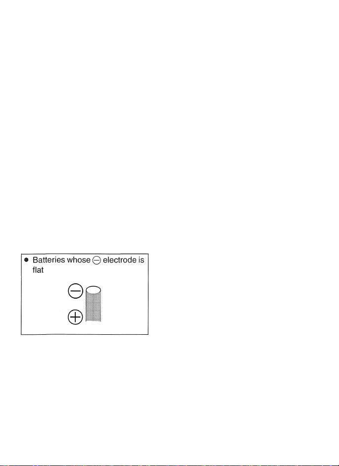
I Batteries with shapes that
cannot be used
Installing batteries with irregular
shapes in the unit may cause
electrolyte leakage, heat
generation and even rupturing of
the batteries themselves.
Some batteries sold on the
market have part or all of their
jackets missing: Under no
circumstances should such
batteries be used. (Refer to the
figure below.)
® Batteries (bare batteries) with
no external jackets or batteries
with parts of their jackets
missing
©
©
■ Handling the batteries
Mishandling of batteries may
cause electrolyte leakage, heat
generation and even rupturing of
the batteries themselves. Heed
with the following cautions.
Do not expose batteries to
water or seawater or allow their
terminal areas to become wet.
Do not remove their external
jackets or damage them in any
way.
Do not drop the batteries,
knock them into other objects
or subject them to any other
kind of strong impact.
Stop using the batteries as
soon as you notice any
electrolyte leakage,
deformation, discoloration or
any other such trouble.
Do not store batteries in
locations where the
temperature and/or humidity
levels are high.
Keep batteries out of the reach
of infants and small children.
Always use 2 new batteries of
the same type when replacing
batteries.
11
VQT1B10
Page 12

Remove the batteries from the
unit when you do not intend to
use the unit for a prolonged
period.
Batteries may be hot
immediately after the unit has
been used. Before removing
them from the unit, turn off the
unit’s power and wait until the
temperature of the batteries
has dropped.
At low temperatures [under
10 °C (50 °F)], the performance
of batteries will deteriorate and
the number of flashes fired by
the unit will be sharply
reduced. The operating
duration of batteries tends to
be shorter particularly when
alkaline dry batteries are used
so warm them in your pocket
before use. When warming
batteries in your pocket, avoid
direct contact with cigarette
lighters and other metal objects
as well as with pocket/body
warmers.
The number of flashes fired by
the unit may also be sharply
reduced if the © and 0
electrodes of the batteries are
exposed to oils from the skin or
other forms of dirt. Before
installing the batteries, wipe the
© and © electrodes carefully
using a soft, dry cloth.
If electrolytes should leak from
the batteries, wipe away all
traces of the electrolyte in the
battery compartment, and then
insert fresh batteries or fully
charged nickel metal hydride
batteries.
If you should get electrolyte on
your hands or clothes, rinse it off
thoroughly with water. If you
should get electrolyte in your
eyes, you risk losing your sight.
In such a case, do not rub your
eyes but immediately wash them
with clean water, and then seek
medical advice.
12
^QT1B10
Page 13

■ Rechargeable nickel metal
hydride batteries
Nickel metal hydride batteries can
be made ready for use by
recharging them using a dedicated
charger. However, mishandling
may cause electrolyte leakage,
heat generation, the ignition of
flames and even rupturing of the
batteries themselves. Heed the
following precautions.
It may not be possible to
properly recharge batteries
with dirty 0 and 0
electrodes. Use a soft, dry
cloth to carefully wipe the 0
and 0 electrodes as well as
the terminal areas of the
charger.
Either when they are
purchased or when they have
not been used for a prolonged
period, nickel metal hydride
batteries may not have a
sufficient charge. This is due
to their characteristics and is
not indicative of trouble. Their
regular performance will be
restored after they have been
charged a number of times.
It is recommended that the
batteries be recharged only
after their existing charge has
been used up. If they are
repeatedly charged without
their existing charge first
having been used up, it may be
difficult for them to sustain their
capacity. (A phenomenon
referred to as the memory
effect.)
If the memory effect has
occurred, use up the existing
charge in the batteries until the
unit cannot fire and then
recharge them fully a number
of times. This will restore their
capacity.
When nickel metal hydride
batteries are not being used,
their capacity will diminish due
to the effects of natural
discharging.
Do not continuously charge
nickel metal hydride batteries
which already have a charge.
Do not remove their external
jackets or damage them in any
way.
Read the instructions
accompanying the charger
used when recharging the
batteries.
13
VQT1B10
Page 14

Nickel metal hydride batteries have
a specific service life. As they are
increasingly used or as time goes
by, their capacity will diminish
gradually. When the length of time
during which the unit can be used
has dropped drastically, the
batteries may have reached the
end of their service life. Obtain
fresh batteries.
® The length of the service life of
batteries differs depending on
their storage method, operating
conditions and the environment
in which they are used.
■ When the unit is not going to
be used for a prolonged
period
® If the batteries are left inside the
unit, a faint current will flow
continuously, even when the
unit’s power is off, gradually
discharging the batteries. If they
are left like this, they may
overdischarge and may become
unusable even when recharged.
® When storing the batteries for a
prolonged period, it is
recommended that they be
charged once a year and that
after their remaining charge has
been used up, they be removed
from the unit and stored again.
H Service life of batteries
Number of flashes
(number of full flashes in
MANUAL mode at intervals of
30 seconds)
Batteries used
Alkaline dry Approx.
batteries (LR6) 120 flashes
Nickel metal
hydride Approx.
batteries
(Ni-MH)
Number of
flashes
200 flashes
Photo taking conditions
® Temperature; 23 °C (73.4 °F)
Flash interval
Batteries used
Alkaiine dry
batteries (LR6)
Nickel metal
hydride
batteries
(umH)
The number of flashes and flash
interval differ slightly depending
on the storage status of the
batteries and the operating
conditions.
Flash interval
Approx. 8 s
i
Approx. 7.5 s
14
VQT1B10
Page 15

Inserting and
Removing the Unit’s
Batteries (optional)
® Check that the unit’s power is
off.
® Use alkaline dry batteries or
rechargeable nickel metal
hydride batteries.
1 Slide the battery cover to
open it.
iii
A ^
■■ I-
® There is tape adhered to the
battery cover the first time that
you use the unit. Peel it off.
2 When inserting the
batteries, ensure that the
0 and 0 poles of the
batteries are aligned
correctly.
3 Close the battery cover
by sliding it back firmly
as far as it will go.
^ \
® After using the unit, take out the
batteries.
15
VQT1B10
Page 16

Checking the
Flash’s Remaining
Battery Charge
® Install the batteries and then
turn on the unit and check the
battery remaining power.
1 Press the [POWER]
button.
POWER
Q^O
® Charging now starts.
2 Check that the [TEST/
CHARGE] button lights.
1
(
mmmmm
liiiiilllllllli
o-
L. '
i
After the batteries have been
fully charged, the [TEST/
CHARGE] button lights.
..
TEST/CHARGE
i CUD
iililB
@ If it takes as long for the [TEST/
CHARGE] button to light as the
period indicated in the table
below, it means that the
batteries are nearly worn out.
Replace them with fresh
batteries as soon as possible.
Alkaline batteries
Rechargeable nickel
metal hydride
batteries
® If the [TEST/CHARGE] button
and [AUTO CHECK] lamp both
flash at the same time, it means
that the batteries are almost
completely worn out and should
be replaced with fresh batteries
as soon as possible.
More
than 30 s
More
than 10 s
3 Press the [POWER]
button to turn off the
unit’s power.
m\.................
® When the [TEST/CHARGE]
button is pressed, the unit may
fire.
® Turn off the power in the
following situations:
® When mounting the unit onto.
or disengaging it from, the
digital camera
® When you do not want the
unit to fire
@ When you are not going to
use the unit
16
VQT1B10
Page 17

Mounting the Unit
onto the Digitai
Camera, and
Removing it
® Check that the power of the
digital camera and unit is off.
(Mounting the unit onto, or
disengaging it from, the camera
while the power is on may cause
trouble and is not
recommended.)
H Mounting the unit
1 Secure the flash head at
the horizontal front
position.
(a): Bounce unlock button
• If the flash head is at the lock
position, rotate it while pressing
the bounce unlock button.
2 Loosen the lock ring.
If the lock pin is protruding, turn
the lock ring in the opposite
direction from [^LOCK] and
retract the pin.
Do not apply more force than is
necessary to the lock ring.
Do not touch the terminal areas
with your fingers, metal objects,
etc.
Do not mount the unit onto the
digital camera while the lock pin
is protruding. Otherwise you
may damage the unit.
17
VQT1B10
Page 18
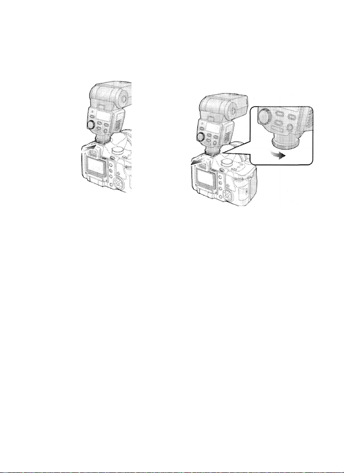
3 Slide the unit firmly
toward the back of the
hot shoe until a clicking
sound is heard.
4 Turn the lock ring in the
[◄LOCK] direction until
it stops turning.
Removing the unit
Completely loosen the
lock ring, and slide the
unit off from the hot
shoe.
18
VQT1B10
Page 19

Taking Pictures
using a Digital
Camera with
Communication
Functions
® For details on each flash mode,
turn to P21 to 25.
1 Turn on the power of the
digital camera.
2 Press the [POWER]
button on the unit.
POWER
Or- •
Press the shutter button
of the digital camera
halfway down.
The ISO sensitivity, aperture,
shutter speed and other photo
taking information are sent
between the digital camera and
the unit.
Press the [MODE]
button, and select the
flash mode.
n
If r
i n
®: Flash mode
® The flash mode is shown on the
display panel.
® The mode is changed each time
the [MODE] button is pressed.
fO Zf
fU.L ■■
MODE
( )
@ The [TEST/CHARGE] button
lights after the batteries have
been fully charged.
19
VQT1B10
Page 20

Concerning the flash modes
Item Details of settings
[TTL AUTO] After measuring the appropriate flash intensity by
[AUTO] The unit senses the light by its flash sensor in
[MANUAL] The unit fires at the guide number (GN)* which
[FP TTL AUTO]
[FP MANUAL]
* The guide number (GN) is a value which indicates the light quantity of
a flash. The higher the value, the greater the quantity of light emitted
by the unit.
® You may not be able to use some modes depending on the type of
digital camera.
discharging a pre-flash, the unit fires again for
photo taking. (P21)
accordance with the aperture of the lens, and it
adjusts the flash intensity. (P22)
® This mode can be used only for digital camera
models with communication functions which
support the [AUTO] mode.
has been set. (P23)
This mode enables flash photo taking even at the
high shutter speeds of the digital camera by FP
firing (repeatedly firing the flash at high speed).
(P24)
The unit initiates FP firing at the flash intensity set
in the [FP MANUAL] mode. (P25)
(O: Available, —: Not available)
20
VQT1B10
[[TTLAUTO]^ [AUTOJ ImANUAm’ j MANUAL] I
DMC-ll K
DMC-FZ50
® It is not possible to select a mode which cannot be used.
0
'0
...........
—
Page 21

*ress the [MODE] button, and
elect the flash mode. (P19)
> The flash working range is
shown on the display panel in
line with the settings of the
digital camera.
: >
3 Check that the [AUTO
CHECK] lamp is flashing.
AUTO CHECK
i n
iLLL. :
3
Flash working range
I Check that the distance
to the subject is within
the flash working range.
> If the subject is outside the
range, adjust the aperture of the
lens or change the distance to
the subject.
^ The flash working range
changes depending on the type
and settings (ISO sensitivity,
aperture and focal length) of the
digital camera used.
I Press the shutter button
all the way down, and
take the picture.
® If the [AUTO CHECK] lamp
continues to flash for about
5 seconds, it means that the unit
has fired successfully. If it does
not flash, the unit has not fired
successfully. Check the settings
on the unit and the digital
camera and then take the
picture again.
21
VQT1B10
Page 22

Press the [MODE] button, and
select the flash mode. (P19)
® The flash working range is
shown on the display panel in
line with the settings of the
digital camera
2 Press the shutter button
all the way down, and
take the picture.
3 Check that the [AUTO
CHECK] lamp is flashing.
.....
""" ^
X
1 1
! AUTO CHECK
n n
u.u
®: Flash working range
• If the settings on the digital
camera (ISO sensitivity and
aperture) are outside the
combinations of the ISO
sensitivity and aperture which
can be adjusted, the flash
working range is not displayed
and the user is warned by the
flashing of [ISO] and [F] on the
display. In a case like this,
change the digital camera
settings.
1 Check that the distance
to the subject is within
the flash working range.
® If the subject is outside the
range, adjust the aperture of the
lens or change the distance to
the subject.
• The flash working range
changes depending on the type
and settings (ISO sensitivity,
aperture and focal length) of the
digital camera used.
22
VQT1B10
O Z*
®
i
!
llllll
If the [AUTO CHECK] lamp
continues to flash for about
5 seconds, it means that the unit
has fired successfully. If it does
not flash, the unit has not fired
successfully. Check the settings
on the unit and the digital
camera and then take the
picture again.
I Combinations of the ISO
sensitivity and aperture which
can be adjusted in the [AUTO]
mode
ISO sensitivity
3200
1600
800
400
200
100
50
25
Aperture
F8 to
F5.6 to
F4 to
F2.8
F2 to
FI .4 to
FI .4 to
FI .4 to
F32
F32
F32
F32
to
F32
F22
F16
F11
Page 23

Press the [MODE] button, and
select the flash mode. (P19)
» The optimum camera to subject
distance and guide number
(GN) matching the digital
camera settings are shown on
the display panel.
A): Optimum camera to subject
distance
1 Turn the select dial and
set the guide number
(GN) so that the optimum
camera to subject
distance is set to the
distance to the subject.
■“j ,r
m
i 1
C J - -
The optimum camera to subject
distance changes depending on
the digital camera settings (ISO
sensitivity, aperture, focal length
and shutter speed).
Press the shutter button
all the way down, and
take the photo.
If the ISO sensitivity is [100], the
optimum camera to subject
distance can be calculated by
dividing the guide number (GN)
by the aperture. (P43)
The optimum camera to subject
distance is an estimate.
i If the optimum camera to subject
distance is closer than 0.6 m
(1.97 feet) [or 0.5 m (1.64 feet)
for close-up photos], the lighting
range of the flash will shift. In
this case, the user is warned by
the flashing of the optimum
camera to subject distance on
the display.
23
VQT1B10
Page 24

Press the [MODE] button, and
select the flash mode. (P19)
® This mode enables flash photo
taking even at the high shutter
speeds of the digital camera by
FP firing (repeatedly firing the
flash at high speed).
® The flash working range is
shown on the display panel in
line with the settings of the
digital camera.
3 Check that the [AUTO
CHECK] lamp is flashing.
AUTO CHECK
O
1
24
VQT1B10
aa
i n
TU
(g): Flash working range
(A)
------
ZOOM
c
1
1 Check that the distance
to the subject is within
the flash working range,
® If the subject is outside the
range, adjust the aperture of the
lens or change the distance to
the subject.
® The flash working range
changes depending on the type
and settings (ISO sensitivity,
aperture and focal length) of the
digital camera used. The range
is narrower than in the [TTL
AUTO] mode.
2 Press the shutter button
all the way down, and
take the photo.
® If the [AUTO CHECK] lamp
continues to flash for about
5 seconds, it means that the unit
has fired successfully. If it does
not flash, the unit has not fired
successfully. Check the settings
on the unit and the digital
camera and then take the
picture again.
The following kinds of photos
can be taken using high shutter
speeds.
® Photo taking with the shadows
softened by backlight photography
® Portrait photos taken outdoors
with an open aperture and with
the background defocused
Page 25

Press the [MODE] button, and
select the flash mode. (P19)
® The optimum camera to subject
distance and guide number
(GN) matching the digital
camera settings are shown on
the display panel.
The optimum camera to subject
distance changes depending on
the digital camera settings (ISO
sensitivity, aperture, focal length
and shutter speed).
Press the shutter button
all the way down, and
take the photo.
S3
i t
i #
(a): Optimum camera to subject
distance
C
1 Turn the select dial and
set the guide number
(GN) so that the optimum
camera to subject
distance is set to the
distance to the subject.
13
■~t r
o
® If the optimum camera to subject
distance is closer than 0.6 m
(1.97 feet) [or 0.5 m (1.64 feet)
for close-up photos], the lighting
range of the flash will shift. In
this case, the user is warned by
the flashing of the optimum
camera to subject distance on
the display.
® The optimum camera to subject
distance is an estimate.
25
VQT1B10
Page 26

■ Adjusting the flash intensity
The flash intensity can be adjusted
in steps.
Set the flash intensity adjustment
to [ON] before adjusting the flash
intensity. (P40)
• [in ] appears on the display
panel.
1 Turn the select dial and
set the flash intensity
adjustment value.
® You cannot adjust the flash
intensity when the guide number
is at the highest or lowest value.
The flash intensity adjustment
range and the actual flash
Intensity may differ depending
on the flash mode.
® Flash intensity adjustment range
® If [TTL AUTO], [AUTO] or [FP
TTL AUTO] is selected, the
flash intensity can be
adjusted over a range of ±3.0
steps.
±0.3 ±0.7-••±3.0
0
26
VQT1B10
Flash intensity adjustment
(A):
value
The flash intensity adjustment
value is always displayed except
when it is [0].
The flash working range
displayed is for when the flash
intensity adjustment value is [0].
0 -0.3 -0.7
If [MANUAL] or [FP MANUAL]
is selected, the flash intensity
can be adjusted over a range
of ±0.7 steps.
±0.3 ±0.7
0
-0.3 -0.7
0
---------
3.0
Page 27

® The actual flash intensity may vary when the flash intensity adjustment
value has been set on both the digital camera and the unit.
® If [TTL AUTO], [AUTO] or [FP TTL AUTO] is selected, the unit fires
at the adjustment value obtained by adding together the adjustment
values set on the digital camera and the unit. (The value set on the
unit only is displayed as the flash intensity adjustment value.)
[Example]
Umt
Adjustment value setting
Unit’s flash Intensity
adjustment value display
Actual adjustment value
used for firing
® If [MANUAL] or [FP MANUAL] is selected, the unit fires at the
adjustment value set on the unit only.
+0.3
Digital camera
+0.3
(+1/3 EV)
+0.3
+0.6
(+2/3 EV)
[Example]
Adjustment value setting
Unit’s flash intensity
adjustment value display
Actual adjustment value
used for firing
Unit
+0.3
Digital camera
+0.3
(+1/3 EV)
+0.3
+0.3
(+1/3 EV)
27
VQT1B10
Page 28

Taking Pictures
using a Digitai
Camera without
Communication
Functions
® For details on each flash mode,
turn to P29 to 32.
1 Press the [POWER]
button on the unit.
® The [TEST/CHARGE] button
lights after the batteries have
been fully charged.
2 Press the [MODE] button
to select the flash mode.
MODE
Í nn
Í uu
J,U
Concerning the flash modes
Item
[AUTO]
[MANUAL] The unit fires at the
The guide number (GN) is a
value which indicates the light
quantity of a flash. The higher
the value, the greater the
quantity of light emitted by the
unit.
Details of settings
The unit senses the
light by its flash
sensor in
accordance with the
aperture of the lens,
and it adjusts the
flash intensity. (P29)
guide number (GN)*
which has been set.
(P32)
28
VQT1B10
®: Flash mode
® The flash mode is shown on the
display panel.
® The mode is changed each time
the [MODE] button is pressed.
Page 29

^ress the [MODE] button, and
select the flash mode. (P28)
1 Press the [ZOOM] button
to set the zoom value to
the focal length of the
lens.
!
2 Press and hold the
[MODE] button and then
turn the select dial within
2 seconds to set the ISO
sensitivity.
MODE
iSC)
i n n
i UiJ
The unit will switch to the
function settings if the [MODE]
button is pressed for more than
2 seconds. (P39)
Turn the select dial and
set it to the aperture of
the lens.
® If the combination of the ISO
sensitivity and aperture are
outside the usable range, a
warning is given in the form of
the flashing ISO sensitivity and
aperture displays. In a case like
this, change the ISO sensitivity
and aperture.
4 Press the shutter button
all the way down, and
take the photo.
5 Check that the [AUTO
CHECK] lamp is flashing.
AUTO CHECK
O
If the [AUTO CHECK] lamp
continues to flash for about
5 seconds, it means that the unit
has fired successfully. If it does
not flash, the unit has not fired
successfully. Check the settings
on the unit and the digital
camera and then take the
picture again.
i nn
f LiU
O
® The flash intensity can be
adjusted in 1/3 steps by varying
the ISO sensitivity and aperture
from the digital camera settings.
29
VQT1B10
Page 30

Flash working range in [AUTO] mode
ISO sensitivity
3200
F8
F5.6
F11
F8
F11
FI 6
F22
FI 6
F32 F22
F32 F22
Aperture values that can he set
400
F4
F2.8
F5.6 F4
F8 F5.6
F11
F11 F8 F5.6
F16
FI 6
F22
F32
F32 F22
800
1800
F8 F5.6
100
2DD
FI .4
F2
F2.8 F2
F4
F2.8
F4
F11
F8 F5.6
F11
F16
FI 6
F32 F22 FI 6 F11
60 2B
FI .4
FI .4
F2
F2
F2.8
F4
F2.8
F4
F8 F5.6
F11 F8
Lighting angle
0.8 m
(2.63 feet) to
8.6 m
(28.2 feet)
0.6 m
(1.97 feet) to
6.0 m
(19.7 feet)
0.5 m
(1.64 feet) to
4.3 m
(14.1 feet)
0.5 m
(1.64 feet) to
3.0 m
(9.84 feet)
0.5 m
(1.64 feet) to
2.1 m
(6.89 feet)
0.5 m
(1.64 feet) to
1.5 m
(4.92 feet)
0.5 m
(1.64 feet) to
1.1 m
(3.61 feet)
0.5 m
(1.64 feet) to
0.8 m
(2.63 feet)
0.5 m
(1.64 feet) to
0.5 m
(1.64 feet)
0.9 m
(2.95 feet) to
10.0 m
(32.8 feet)
0.6 m
(1.97 feet) to
7.0 m
(23.0 feet)
0.5 m
(1.64 feet) to
5.0 m
(16.4 feet)
0.5 m
(1.64 feet) to
3.5 m
(11.5 feet)
0.5 m
(1.64 feet) to
2.5 m
(8.20 feet)
0.5 m
(1.64 feet) to
1.8 m
(5.91 feet)
0.5 m
(1.64 feet) to
1.3 m
(4.27 feet)
0.5 m
(1.64 feet) to
0.9 m
(2.95 feet)
0.5 m
(1.64 feet) to
0.6 m
(1.97 feet)
30
VQT1B10
® The areas framed by the bold lines indicate the flash working range
when the wide panel is used. (P37)
Page 31

12 [24)
1.3 m
(4.27 feet) to
14.3 m
(46.9 feet)
0.9 m
(2.95 feet) to
10.0 m
(32.8 feet)
0.6 m
(1.97 feet) to
7.1 m
(23.3 feet)
0.5 m
(1.64 feet) to
5.0 m
(16.4 feet)
0.5 m
(1.64 feet) to
3.6 m
(11.8 feet)
0.5 m
(1.64 feet) to
2.5 m
(8.20 feet)
0.5 m
(1.64 feet) to
1.8 m
(5.91 feet)
0.5 m
(1.64 feet) to
1.3m
(4.27 feet)
0.5 m
(1.64 feet) to
0.9 m
(2.95 feet)
Focal ìengih (mai) |3$ mm film conversion)
14(26)
17 (35)
2$ (SO)
35 (70)
1.5m'
(4.59 feet) to
15.7 m
(51.5 feet)
I. 0 m
(3.28 feet) to
II. 0m
(36.1 feet)
0.7 m
(2.30 feet) to
7.9 m
(25.9 feet)
0.5 m
(1.64 feet) to
5.5 m
(18.0 feet)
0.5 m
(1.64 feet) to
3.9 m
(12.8 feet)
0.5 m
(1.64 feet) to
2.8 m
(9.19 feet)
0.5 m
(1.64 feet) to
2.0 m
(6.56 feet)
0.5 m
(1.64 feet) to
1.4m
(4.59 feet)
0.5 m
(1.64 feet) to
1.0m
(3.28 feet)
(4.92 feet) to
17.1 m
(56.1 feet)
1.1 m
(3.61 feet) to
12.0 m
(39.4 feet)
0.8 m
(2.63 feet) to
8.6 m
(28.2 feet)
0.5 m
(1.64 feet) to
6.0 m
(19.7 feet)
0.5 m
(1.64 feet) to
4.3 m
(14.1 feet)
0.5 m
(1.64 feet) to
3.0 m
(9.84 feet)
0.5 m
(1.64 feet) to
2.2 m
(7.22 feet)
0.5 m
(1.64 feet) to
1.5 m
(4.92 feet)
0.5 m
(1.64 feet) to
1.1 m
(3.61 feet)
(5.91 feet) to
20.0 m
(65.6 feet)
1.3 m
(4.27 feet) to
14.0 m
(45.9 feet)
0.9 m
(2.95 feet) to
10.0 m
(32.8 feet)
0.6 m
(1.97 feet) to
7.0 m
(23.0 feet)
0.5 m
(1.64 feet) to
5.0 m
(16.4 feet)
0.5 m
(1.64 feet) to
3.5 m
(11.5 feet)
0.5 m
(1.64 feet) to
2.5 m
(8.20 feet)
0.5 m
(1.64 feet) to
1.8m
(5.91 feet)
0.5 m
(1.64 feet) to
1.3m
(4.27 feet)
(6.56 feet) to
22.9 m
(75.1 feet)
(4.59 feet) to
16.0 m
(52.5 feet)
(3.28 feet) to
(37.4 feet)
(2.30 feet) to
(26.2 feet)
(1.64 feet) to
(18.7 feet)
(1.64 feet) to
(13.1 feet)
(1.64 feet) to
(9.51 feet)
(1.64 feet) to
(6.56 feet)
(1.64 feet) to
(4.92 feet)
Working range when taking pictures in [AUTO]
2Tm
1.4 m
I. 0 m
II. 4m
0.7 m
8.0 m
0.5 m
5.7 m
0.5 m
4.0 m
0.5 m
2.9 m
0.5 m
2.0 m
0.5 m
1.5 m
42 (85)
(7.55 feet) to
25.7 m
(84.3 feet)
1.6 m
(5.25 feet) to
18.0 m
(59.1 feet)
1.1 m
(3.61 feet) to
12.9 m
(42.3 feet)
0.8 m
(2.63 feet) to
9.0 m
(29.5 feet)
0.6 m
(1.97 feet) to
6.4 m
(21.0 feet)
0.5 m
(1.64 feet) to
4.5 m
(14.8 feet)
0.5 m
(1.64 feet) to
3.3 m
(10.8 feet)
0.5 m
(1.64 feet) to
2.3 m
(7.55 feet)
0.5 m
(1.64 feet) to
1.6m
(5.25 feet)
When the flash head is facing toward the front, the number displayed
at the near-distance side is 0.6 m (1.97 feet) or more, and when it is
pointed downward, it is 0.5 m (1.64 feet) or more. 31
VQT1B10
Page 32

Press the [MODE] button, and
select the flash mode. (P28)
® The guide number (GN) appears
on the display panel.
t
®: Guide number (GN)
1 Press the [ZOOM] button
to set the zoom value to
the focal length of the
lens.
If guide number (GN) display is
set to [OFF], the light quantity
can be displayed as the light
quantity ratio.
The “light quantity ratio” is the
ratio of the flash intensity to the
full flash.
32
VQT1B10
C u
M zocm
n
ZOOM
2 Turn the select dial and
set the guide number
(GN).
. u
!0
3 Press the shutter button
all the way down, and
take the photo.
Page 33

■ How to determine the guide
number, the aperture and the
optimum camera to subject
distance
When the camera to subject
distance and aperture have been
decided upon
® The following formula is used to
obtain the guide number (GN),
which is then set in the unit.
“Aperture (F)’' x “Camera to
subject distance (m)” ^ “ISO
sensitivity coefficient*”
When the aperture is to be set
® The following formula is used to
obtain the aperture, which is
then set in the digital camera.
“Guide number (GN)” x “ISO
sensitivity coefficient*” “Camera
to subject distance (m)”
How to obtain the optimum
camera to subject distance
“Guide number (GN)” x “ISO
sensitivity coefficient*” -i“Aperture (F)”
* ISO sensitivity coefficient
ISO sensitivity
3200 5.6
1600
800 2.8
400
200
100
50
25
® For a list of guide numbers (GN),
turn to P43.
Compensation 1
coefficient
4.0
2.0
1.4
1.0
0.71
0.5
33
VQT1B10
Page 34

other Applications
Bounce light photography is a
technique which uses the
reflected light from a ceiling or a
wall onto which the light emitted
from a flash unit has been
directed.
If the flash is aimed directly at
the front of the subject when the
portrait of a person is to be
taken, for instance, strong
shadows may form or the
person’s skin and other areas
may appear whitish and
indistinct. However, if the
bounce light technique is used
at times like this, the strong
shadows can be minimized and
the subject captured naturally.
While holding down the
bounce unlock button,
turn the flash head so
that it is pointing in the
desired direction.
At the locked position, change
the direction while holding down
the bounce unlock button.
Point the flash at the
ceiling or other reflective
surface, and take the
photo.
The flash working range and
optimum camera to subject
distance do not appear on the
display panel.
When the lighting angle is set to
[ZOOM] (auto), the zoom value
appears on the display panel as
[--] and 25 mm [135 camera
(35 mm film conversion):
50 mm] is set.
The lighting angle can be
changed manually. (P36)
34
VQT1B10
90^
Page 35

m
' We recommend taking a test
photo to decide the proper
exposure. Check the exposure
using the histogram function on
your digital camera. For further
details, refer to the operating
instructions of your digital
camera.
' When the [TEST/CHARGE]
button is pressed, the [AUTO
CHECK] lamp lights, and
whether or not the firing is
appropriate can be verified.
(This is possible only when
[AUTO] is established as the
flash mode.)
' If the surface (such as the
ceiling or walls) off which the
light from the flash is to be
reflected is colored, this may
affect the photo images. Choose
a surface which is white or offwhite as the reflecting surface.
When the camera to subject
distance is 0.5 m (1.64 feet) to
1 m (3.28 feet), the light emitted
from the flash will be skewed.
For this reason, while holding
down the bounce unlock button,
point the flash head downward
(7 degrees), and then take the
picture.
Point the flash head down as far as it will go (7 degrees downward).
panel.
Vignetting may be caused by the
light from the flash when the
lens has a long overall length or
a large diameter. Take a test
photo first, and then take the
picture.
Use the flash in this way only for
close-up photos. If you keep the
flash head pointed down during
regular photo taking, the light
emitted from the flash at the top
of the screen will be insufficient.
35
VQT1B10
Page 36

The lighting angle can be
adjusted manually.
Press the [ZOOM]
button, and select the
lighting angle.
The zoom values that are
appropriate for the flash lighting
angle appear:
ZOOM
...
.
M ZOOM 12 (24) ¡y
MZOOM 14(28)
M ZOOM 17 (35)
# n
(A): Lighting angle
• [M ZOOM] appears on the
display panel.
'"f m
(A)
Any of the following ZOOM
settings can be selected:
12 mm, 14 mm, 17 mm, 25 mm,
35 mm, 42 mm
[With a 135 camera (35 mm film
conversion): 24 mm, 28 mm,
35 mm, 50 mm, 70 mm, 85 mm]
ZOOM
M ZOOM 25 (50)
M ZOOM 35 (70)
M ZOOM 42 (85)
• [ZOOM] can be used only when
a digital camera with
communication functions is
used.
® When the wide panel is used,
any of the following settings can
be selected: [ZOOM], [10 (20)]
or [8 (16)].
The number that appears at the
top right of the display panel is
the flash lighting angle.
When the lighting angle is set to
[ZOOM] (auto), the zoom value
is set between 12 mm (24 mm)
and 42 mm (85 mm).
When a value higher than the
focal length of the lens used is
selected, the edges of the
images will darken.
36
VQT1B10
Page 37

Use the built-in wide panel for
flash photography when the
focal length of the lens is wider
than 12 mm.
Set wide panel switching to
[ON]. (P40)
Pull out the wide panel and then push it down.
panel.
2 Press the [ZOOM]
button, and select the
lighting angle.
irt
tUmti
4 n
1 m J
When using the wide panel, the
guide number (GN) is reduced.
This means that the working
range is reduced when taking
photos in the [TTL AUTO], [AUTO]
or [FP TTL AUTO] mode and that
the optimum camera to subject
distance is reduced when taking
photos in the [MANUAL] or [FP
MANUAL] range.
After taking the photos, retract
the wide panel.
Do not push the wide panel
upward. Otherwise it may be
damaged.
ZOOM
i
®
(A): Lighting angle
® ZOOM, 8 mm or 10 mm [ZOOM,
16 mm or 20 mm for a 135
camera (35 mm film
conversion)] can be selected.
37
VQT1B10
Page 38

Many different flash
photography applications can be
chosen by the digital camera
settings.
It may not be possible to use
some functions depending on
the functions and shape of the
digital camera used.
For further details, refer to the
operating instructions of your
digital camera.
Select [TTL AUTO] or [FP TTL
AUTO] as the flash mode.
Red-eye reduction flash
® The light emitted by the flash
reduces red eye where the eyes
of the subjects appear red.
2nd curtain synchronization
When taking slow-shutter shots
of moving subjects, the flash is
activated just before the shutter
closes.
Light sources emanating from
behind the subject are captured
to achieve a dynamic feeling.
38
VQT1B10
Slow synchronization
Light from the unit can be
emitted using the slow shutter.
This enables shots of people to
be taken clearly against the
backdrop of night scenes.
Page 39

Functions
® You can set each function in
advance.
1 Press the [POWER]
button.
2 Press the [MODE] button
for 2 or more seconds to
switch to the function
settings.
■ Returning the function
settings to the default status
(status at the time of
purchase)
When the [MODE] button and
[LIGHT] button are pressed
together for two or more seconds,
all the settings except for the
distance display (m/ft) are returned
to their defaults.
MODE
€111
3 Press the [MODE] button
lightly to select the menu
item.
zoou
MODE
iiiii
4 Turn the select dial to
select the setting.
JOOV
wmWi
5 Press the [MODE] button
for 2 or more seconds to
exit the settings.
MODE
CZ3
LIGHT
The setting for the distance
display (m/ft) remains
unchanged.
39
VQT1B10
Page 40

Press the [MODE] button for 2 or more seconds to switch to the function
settings. (P39)
Item
AF assist lamp A: The AF assist lamp lights, and focusing
t 1 1
1 L i.
® AF assist will not work with digital cameras which are not part of
Panasonic’s “Four Thirds” system.
® 135 camera: This is a synonym for a 35 mm film camera format.
Distance display
OFF: The AF assist lamp does not light.
4-3: The lighting angle is indicated by the
135: The lighting angle is converted into the
ft: Distances are indicated in feet,
m: Distances are indicated in meters.
is facilitated.
focal length of the lens for the format
used with the “Four Thirds” digital
camera.
focal length of a 35 mm film camera.
Setting
ft
m
Flash intensity
adjustment
Wide panel
switching
ON: The flash intensity is adjusted.
OFF: The flash intensity is not adjusted.
ON: The wide panel takes effect. The unit
recognizes that the wide panel is
extended.
OFF: The wide panel has no effect.
40
VQT1B10
Page 41

item
Guide number ON: The light quantity of the flash is
(GN) display
OFF: The light quantity of the flash is
displayed as a guide number (GN).
displayed as the light quantity ratio.
Setting
GN
ISO sensitivity
and aperture
adjustment
ON: The ISO sensitivity and the aperture
are adjusted to match the digital
camera.
OFF: The ISO sensitivity and the aperture
can be adjusted with the select dial.
ISO F
® This can only be used for digital cameras with communication
functions. (Only when the flash mode is set to [AUTO] mode.)
ISO sensitivity
adjustment
The ISO sensitivity can be set between 25 and
3200.
ISO
® This can be used for digital cameras with communication functions if
ISO sensitivity and aperture adjustment is set to [OFF] and for digital
cameras without communication functions. (Only when the flash
modes are set to [AUTO] mode)
® The {[ i P] function does not work. There is no problem operating
the flash if you select either [ON] or [OFF].
41
VQT1B10
Page 42

Concerning Continuous Firing
When the flash is fired continuously, its flash head becomes hot, and this
may possibly lead to deterioration or malfunction of the unit. Keep
continuous firing within the number of times given below, and then allow
the unit to rest for at least 10 minutes.
Restriction on number of flashes during continuous firing
Flash intensity
1/1
(FULL)
1/2 3s 20
1/4
1/8 to 1/128 0.5 s or less
Continuous firing is synchronized up to the number of frames listed
below. If the restriction on the number of flashes during continuous firing
is exceeded, allow the unit to rest for at least 10 minutes.
Flash interval
6s 10
1 s 40
Number of frames for which continuous firing is possible (serial
photography speed: 8 frames per second)
Light quantity
1/4
1/8
1/16 10
1/32 16
1/64
1/128 40
^ No. of frames
Restriction on
number of
flashes
80
.
............2.............
5
30
42
VQT1B10
Page 43

Table of Guide Numbers (GN)
® The tables show the values when the ISO sensitivity is [100].
® Depending on the digital camera lens, you may not be able to select
the lighting angles in the tables as the focal length is decided by the
camera.
® You can adjust the lighting angle between 12 mm (24 mm) and 42 mm
(85 mm) if you are using the DMC-L1K.
[TTL AUTO]/[AUTO]
Full flash I 12
[MANUAL]
Light
quantity
ratio
1/1
1/2
1/4
1/8
1/16
1/32
1/64
1/128
[
I 8
(16)
a
(16)
“ 12.0 '
8.5
6.0
4.2
3.0
2.1
1.5
1.1 1.2
Focal length (mm) {35 mm film conversion)
...10..
(20)
Focal
ength {
10
m
““Tío''“'
9.9
7.0
4.9
3.5
2.5 3.5 3.9 4.2
1.8
Lighting angle
■ ”T4
12
(28)
m
'20
' 22
Ugh tin
mm) (3$
14
(24)
(28)
.
'""20."0''"
'2“2"“6""'
14.1 15.6
10.0 11.0
7.1
7.8 8.5
5.0 5.5 6.0
2.5 2.8 3.0
1.9
1.8
17
m
24
g angle
mm fil
(36)
" "'2Í 0 '
17.0
12.0
2.1
25 1 35''^
(50) 1 (70)
““'^28'“""|
m convi
jrsion)
..ii....
C50)
19.8
14.0
9.9 11.3
7.0 8.0
4.9
3.5 4.0
2.5
42
(86)
..
36
............
42
(86)
(70)
"36.0“
25.5
22.6
16.0 18.0
12.7
9.0
6.4
5.7
4.5
3.2
2.8
'32
........
43
VQT1B10
Page 44

[FP TTL AUTO]
Shutter
speed
(16) (20)
Focal length (mm) (35 mm film conversion)
a 10
12
(24)
1/125 8.5 9.9 14.1 15.6
1/160
7.5
8.8
12.5
1/200 6.7 7.8 11.2 12.3
1/250 6.0 7.0 10.0 11.0
1/320 5.3
1/400
1/500 4.2
1/640 3.8
1/800 3.4 3.9
1/1000
1/1250 2.7 3.1
1/1600 2.4 2.8
1/2000
1/2500 1.9
6.2
4.7 5.5
4.9
4.4
3.5
3.0
2.5
2.1
2.2
8.8
7.9
7.1 7.8
6.3 6.9
5.6 6.1
5.0 5.5
4.5
4.0
3.5 3.9
3.2 3.5
1/3200 1.7 2.0 2.8 3.1
1.3
1.8
2.5 2.8
1.6 2.2
1.4
2.0
1.8
1/4000 1.5
1/5000
1/6400 1.2
1/8000 1.1 1.2
Lighting angle
IT
14
(35)
(28)
13.8
9.7 10.6
8.7 9.5 11.1
4.9
4.3
2.5
2.2
1.9
(50) {Щ (85)
17.0
19.8
15.0 17.5 20.0 22.5
13.4 15.7 17.9 20.1
12.0 14.0
12.4 14.1 15.9
8.5 9.9
7.5 8.8
6.7
6.0 7.0
5.4
4.7
4.2
3.8 4.4 5.1
3.4
3.0 3.5
2.7
2.4
2.1
25 35
22.6 25.5
16.0 18.0
12.6 14.2
7.8
6.3
5.5
4.9
3.9
3.1
2.8
2.5
42
12.7
11.3
10.0 11.3
8.9 10.1
8.0 9.0
7.2
8.0
7.1
6.3
6.4
5.7
5.7
4.5 5.0
4.0 4.5
3.6 4.0
3.2
3.6
3.2
2.8
44
VQT1B10
Page 45

[FP MANUAL]
® Listed below are the guide numbers (GN) for 1/1 (FULL) flashes.
Shutter
Speed
(16)
1/125
1/160
1/200
1/250 6.0
1/320 5.3
1/400
1/500
1/640 3.8
1/800
1/1000 3.0
1/1250
1/1600
1/2000
1/2500 1.9 2.2
1/3200
1/4000 1.5
1/5000 1.3
1/6400
1/8000 1.1 1.2 1.8
® In the [FP MANUAL] mode, the following formula can be used to obtain
the guide numbers (GN) when any setting except 1/1 is used for the
light quantity.
Guide number (GN) = Guide number for 1/1 x light quantity ratio
coefficient*
Focal length (mm) (35 mm film conversion)
8
10
(20)
8.5 9.9
7.5 8.8 12.5 13.8
6.7
7.8
7.0 10.0
6.2 8.8 9.7
4.7 5.5
4.2 4.9 7.1
4.4
3.4 3.9 5.6 6.1
3.5 5.0
2.7 3.1 4.5
2.4 2.8 4.0
2.1
2.5 3.5 3.9 4.2 4.9
1.7
2.0 2.8 3.1 3.4 3.9 4.5
1.8
1.6 2.2
1.2
1.4
Lighting angle
14
12
(24)
14.1
11.2
7.9
6.3
3.2
2.5 2.8
2.0 2.2 2.4 2.8 3.2 3.6
■l7
(35)
(28)
15.6
12.3 13.4
11.0 12.0
8.7
7.8
6.9
5.5
4.9
4.3
3.5 3.8
2.5
1.9
(50)
19.8 22.6 25.5
17.0
17.5 20.0 22.5
15.0
15.7
14.0 16.0 18.0
12.4
10.6
11.1 12.6 14.2
9.5
8.5 9.9 11.3 12.7
7.5 8.8 10.0 11.3
6.7
7.8 8.9
6.0 7.0 8.0
5.4 6.3 7.2
4.7 5.5
4.4 5.1
3.0 3.5 4.0 4.5
2.7
3.1
2.1 2.5 2.8
25
35 42
(70)
17.9
14.1 15.9
6.3
5.7 6.4
3.6 4.0
(85)
20.1
10.1
9.0
8.0
7.1
5.7
5.0
3.2
* Light quantity ratio coefficient
Light quantity ratio 1/1
Light quantity ratio
coefficient
1.0
1/2 1/4 1/8
0.71 0.5 0.35
1/16
0.25
45
VQT1B10
Page 46

Troubleshooting
MQ&A for the unit
The unit becomes hot.
When the unit is fired continuously
immediately after the [TEST/
CHARGE] button has lighted, the
batteries will generate heat, but
this does not pose any problems in
terms of performance or quality. In
cases like this, wait until the flash
head and batteries cool off before
resuming use.
1 can’t instail the unit on my digital camera.
Is the lock pin protruding?
You cannot install the unit on your
digital camera if this pin is
protruding.
® Turn the lock ring in the opposite
direction from [^LOCK] until it
stops and retract the pin before
proceeding to install the unit on
the digital camera.
1 can’t select the flash modes
even by pressing the [MODE]
button.
When connecting the unit to some
digital camera models capable of
communication, you can select the
flash’s mode only from the digital
camera.
The coloring of the images differs from what 1 see.
Adjust the white balance of the
digital camera. (Setting to the
[AUTO] mode is recommended.)
The images are too bright.
Is the subject closer than the flash
working range? Adjust the flash
working range using one of the
operations below.
® Adjust the aperture of the lens.
® Set the flash intensity to a [-]
value.
• Use the wide panel.
The flash working range does
not appear on the display panel.
The flash working range is not
displayed in the following cases:
® When the lens has been
detached
® When bounce light photography
is performed
® When the light intensity is
adjusted
® When the ISO sensitivity or
aperture setting is outside the
range
The display panel is
extinguished even though the
unit’s power is on.
Is the digital camera’s power
saving function working?
The flash is coupled to the digital
camera so that when the digital
camera’s power-saving function is
working, the flash’s display panel
will be extinguished.
® Press the digital camera’s
shutter button halfway down to
release the function.
46
VQT1B10
Page 47

The flash’s power does not go
off even though I turned off the
power of my digital camera
which comes with
communication functions.
When the power of a digital
camera with communication
functions is switched off, the flash
is set to the power-saving mode.
When the power of the digital
camera is turned back on, the
flash’s power is also turned on.
When the flash’s power is to be
turned off, turn off its power first.
When the flash is used in
combination with a digital camera
without communication functions, it
is automatically set to the power
saving mode when no operations
have been performed for about
15 minutes.
I can’t switch to the lighting
angle.
Has the wide panel been
damaged?
® If the wide panel is damaged
while it is extended, you will no
longer be able to use the
[ZOOM] button. In this case, you
can use the [ZOOM] button if
you set wide panel switching to
[OFF].
■ Q&A for the panel display
[ISO] and [F] are flashing or the
numbers for the ISO sensitivity
and aperture are flashing.
This means that the ISO sensitivity
and aperture of the digital camera
are outside the flash working range
of the flash.
Change the ISO sensitivity and
aperture of the digital camera.
The optimum camera to subject
distance is flashing.
The flash is too close to the
subject.
If the subject is too close, the
lighting range of the flash will shift
so take photos at a distance further
than 0.6 m (1.97 feet) [or 0.5 m
(1.64 feet) for close-up photos].
[ ] and the lighting angle are
flashing.
Extend the wide panel.
[ ^ ] does not go off.
The flash head has been set to
point downward (7 degrees). Do
not use this setting unless you are
taking close-ups.
[ ] does not go off.
The wide panel is extended.
® The guide number (GN) is
reduced.
Pay attention to the camera to
subject distance.
47
VQT1B10
Page 48

48
VQT1B10
Cautions for Use
■ Concerning the unit
• Do not look directly at the
flash at close range when it is
activated.
® Avoid bringing the unit into close
proximity with objects. Its heat
and light may cause deformation
or discoloration.
® When taking photos outside the
flash working range, the proper
exposure will not be achieved,
and images which are whitish or
too dark may be taken.
• At high shutter speeds, the
effects obtained by the unit may
not be sufficient.
Keep the unit away from
insecticide sprays and other
volatile substances.
® If the unit is exposed to these
sprays or substances, its
external case may deteriorate
and/or its paint may peel off.
® Do not leave the unit in contact
with any items made of rubber
or PVC for prolonged periods of
time.
Do not use benzine, paint
thinners, alcohol or other such
solvents to maintain the unit.
® Remove the batteries before
proceeding with maintenance.
® Use of solvents may cause a
deterioration in the unit’s external
case and/or the paint to peel off.
® Wipe away dust and fingerprints
using a soft, dry cloth.
® Do not use kitchen detergents or
chemical cleaning cloths.
® If rain or drops of water splash
onto the unit, wipe off the water
with a dry cloth.
Do not carry the unit when it is
still attached to the camera
body.
® Under no circumstances should
the unit be stored in any of the
following locations since doing
so may cause trouble in
operation or malfunctioning.
® In direct sunlight or on a
beach in summer
® In locations with high
temperatures and humidity
levels or where the changes
in temperature and humidity
are acute
® In locations with high
concentrations of sand, dust
or dirt
® Where there is fire
® Near heaters, air conditioners
or humidifiers
® Where water may make the
unit wet
® Where there is vibration
® Inside a vehicle
® Multiple-light shots cannot be
taken by using the flash in
combination with other flash
units.
® Do not drop the unit, knock it
into other objects or subject it to
any other kind of strong impact
or shock.
Page 49

® When the unit is not going to be
used for a prolonged period,
mold and other problems may
cause failure of the unit. It is
recommended that you check
the unit’s operation prior to use.
® Do not touch the unit’s electrical
contacts. Doing so can cause
failure of the unit.
® To safeguard the flash head
from overheating and
deterioration, stop using the unit
after 10 continuous firings at the
full flash intensity, and allow the
unit to rest for at least
10 minutes to ensure that the
flash head cools off.
^Concerning the batteries
Be sure to remove the batteries
when you will not be using the
camera for a long period of time.
® If the temperature is too high or
low, the terminals may rust
causing a malfunction.
If you drop the batteries
accidentally, check to see if the
body of the batteries or the
terminals are damaged.
• Inserting a damaged battery in
the camera will damage the
camera.
Dispose of unusable batteries.
® Batteries have a limited life.
® Do not throw batteries into fire
because they may cause an
explosion.
® The unusable battery should be
discarded in accordance with
battery recycling laws. Call the
RBRC hotline on 1-800-8228837 for information.
Do not allow battery terminals to
come into contact with metal
objects (such as necklaces,
hairpins, etc.).
® This can cause short circuiting
or heat generation and you may
be badly burned if you touch the
batteries.
Do not attempt to recharge dry batteries.
Do not throw batteries into a fire
or expose to excessive heat
such as sunshine.
Bring charged spare batteries when going out.
® Be aware that the operating time
of the batteries becomes shorter
in low temperature conditions
such as at a ski resort.
49
VQT1B10
Page 50

Specifications
Power requirements: DC 3.0 V
50
VQT1B10
Batteries
recommended for use
Charging time
(from full flash until the
[TEST/CHARGE]
button lights)
Firing period Approx. 1/20000 s to 1/500 s
No. of flashes
(with full flash)
Flash modes TTL AUTO/AUTO/MANUAL/
Bounce angle Upward: 0 to 90 degrees,
Power-saving mode Coupled to power-saving mode of a digital
AF assist lamp Only for combinations with digital camera
Guide number Automatically selected
AA Alkaline dry batteries (LR6)x 2/
AA Rechargeable nickel metal hydride
batteries (Ni-MH)x 2
Approx. 8 s: AA Alkaline dry batteries
Approx. 7.5 s: AA Rechargeable nickel metal
hydride batteries
(Varies depending on the flash intensity; FP
firing excluded.)
Approx. 120 flashes: AA Alkaline dry batteries
Approx. 200 flashes: AA Rechargeable nickel
metal hydride batteries (2700 mAh type)
(Differs depending on the photo taking conditions.)
FP TTL AUTO/FP MANUAL
downward: 0 to 7 degrees,
toward the right: 0 to 90 degrees,
toward the left: 0 to 180 degrees
camera having communication capability
having communication capability
approximate distance enabling automatic
lighting at low-brightness levels: 1 m
(3.28 feet) to 5 m (16.4 feet)
(Differs depending on the digital camera and
type of lens used)
36: At 42 mm setting
(85 mm when a 135 camera is used)
20: At 12 mm setting
(24 mm when a 135 camera is used)
8/10 selected: When the wide panel is used
Page 51

Lighting angle
Dimensions
Mass
Operating
temperature
Operating humidity
Automatically selected
At 12 mm setting: 61 degrees up/down, 78
degrees left/right
(View angle of 12 mm lens covered)*
At 42 mm setting: 21 degrees up/down, 28
degrees left/right
(View angle of 42 mm lens covered)*
Using wide panel: 83 degrees up/down, 101
degrees left/right
(View angle of 8 mm lens covered)*
* When “Four Thirds” applies as the ZOOM
display
Approx. 67 mm (W)x108 mm (H)x
95 mm (D)
[2 11/16" (W)X4 5/16" (H)X3 3/4"(D)]
(excluding the projecting parts)
Approx. 270 g/9.52 oz (main unit)
Approx. 320 g/11.3 oz (including batteries)
0°C to 40 °C (32 °Fto104 °F)
10% to 80% (no condensation)
51
VQT1B10
Page 52

Limited Warranty
FOR U.S.A.
PANASONIC CONSUMER
ELECTRONICS COMPANY,
DIVISION OF PANASONIC
CORPORATION OF NORTH
AMERICA
One Panasonic Way,
Secaucus, New Jersey 07094
PANASONIC PUERTO RICO,
INC.
Ave. 65 de infantería, Km. 9.5,
San Gabriel Industrial Park,
Carolina, Puerto Rico 00985
Digital Still Camera
ACCESSORIES LIMITED WARRANTY
Limited Warranty Coverage
If your product does not work properly because of a defect in
materials or workmanship, Panasonic Consumer Electronics
Company or Panasonic Puerto Rico, Inc. (collectively referred to as
“the warrantor”) will, for the length of the period indicated on the
chart below, which starts with the date of original purchase
(“warranty period”), at its option either (a) repair your product with
new or refurbished parts, or (b) replace it with a new or a refurbished
product. The decision to repair or replace will be made by the
warrantor.
For ninety (90) days—AC Adaptors, Flashes, Conversion
Lenses, Filters, Lens Adaptors, Marine Cases
For ten (10) days—Batteries (Non-rechargeable batteries are
not warranted.)
You must Mail-In your product during the warranty period. This warranty
only applies to products purchased and serviced in the United States or
Puerto Rico. This warranty is extended only to the original purchaser of a
new product which was not sold “as is”.
52
VQT1B10
Page 53

Mail-tn Service
For assistance in obtaining service in the United States please
contact:
Panasonic Services Company Panasonic Plus Department
20421 84th Avenue South
Kent, WA 98032
Phone: 1-800-833-9626
Fax: 1-800-237-9080
If repair is needed during the warranty period the purchaser will be
required to furnish a sales receipt/proof of purchase indicating date of
purchase.
Also, purchaser will be responsible for shipping the unit to the above
address.
For assistance in Puerto Rico call Panasonic Puerto Rico, Inc. (787)-
750-4300 or fax (787)-768-2910.
Limited Warranty Limits And Exclusions
This warranty ONLY COVERS failures due to defects in materials or
workmanship, and DOES NOT COVER normal wear and tear or
cosmetic damage. The warranty ALSO DOES NOT COVER damages
which occurred in shipment, or failures which are caused by products not
supplied by the warrantor, or failures which result from accidents, misuse,
abuse, neglect, mishandling, misapplication, alteration, faulty installation,
set-up adjustments, misadjustment of consumer controls, improper
maintenance, power line surge, lightning damage, modification, or
commercial use (such as in a hotel, office, restaurant, or other business),
rental use of the product, service by anyone other than a Factory
Servicenter or other Authorized Servicer, or damage that is attributable to
acts of God.
53
VQT1B10
Page 54

THERE ARE NO EXPRESS WARRANTIES EXCEPT AS LISTED
UNDER “LIMITED WARRANTY COVERAGE”. THE WARRANTOR
IS NOT LIABLE FOR INCIDENTAL OR CONSEQUENTIAL DAM
AGES RESULTING FROM THE USE OF THIS
PRODUCT, OR ARISING OUT OF ANY BREACH OF THIS WAR
RANTY.
(As examples, this excludes damages for lost time, travel to and
from the servicer, or loss of, or failure to obtain, images, data or
other camera memory content. The items listed are not exclu
sive, but are for illustration only.) ALL EXPRESS AND IMPLIED
WARRANTIES, INCLUDING THE WARRANTY OF
MERCHANTABILITY, ARE LIMITED TO THE PERIOD OF THE LIM
ITED WARRANTY.
Some states do not allow the exclusion or limitation of incidental or
consequential damages, or limitations on how long an implied warranty
lasts, so the exclusions may not apply to you.
This warranty gives you specific legal rights and you may also have
others rights which vary from state to state. If a problem with this product
develops during or after the warranty period, you may contact your dealer
or Servicenter. If the problem is not handled to your satisfaction, then
write to the warrantor’s Consumer Affairs Department at the addresses
listed for the warrantor.
PARTS AND SERVICE WHICH ARE NOT COVERED BY THIS LIMITED
WARRANTY ARE YOUR RESPONSIBILITY.
54
VQT1B10
Page 55

FOR CANADA
Panasonic Canada Inc.
5770 Ambler Drive, Mississauga, Ontario L4W 2T3
PANASONIC PRODUCT - LIMITED WARRANTY
Panasonic Canada Inc. warrants this product to be free from defects
in material and workmanship and agrees to remedy any such defect
for a period as stated below from the date of original purchase.
Digital Camera
Digital Photo
Peripherals
Digital Camera
Accessories
LIMITATIONS AND EXCLUSIONS
This warranty does not apply to products purchased outside Canada
or to any product which has been improperly installed, subjected to
usage for which the product was not designed, misused or abused,
damaged during shipping, or which has been altered or repaired in
any way that affects the reliability or detracts from the performance,
nor does it cover any product which is used commercially. Dry cell
batteries, printer ink cartridge and paper are also excluded from
coverage under this warranty.
This warranty is extended to the original end user purchaser only. A
purchase receipt or other proof of date of original purchase is
required before warranty service is performed.
One (1) year, parts and labour
One (1) year, parts and labour
Ninety (90) days, parts and labour
55
VQT1B10
Page 56

THIS EXPRESS, LIMITED WARRANTY IS IN LIEU OF ALL
OTHER WARRANTIES, EXPRESS OR IMPLIED, INCLUDING
ANY IMPLIED WARRANTIES OF MERCHANTABILITY AND
FITNESS FOR A PARTICULAR PURPOSE.
IN NO EVENT WILL PANASONIC CANADA INC. BE LIABLE FOR
ANY SPECIAL, INDIRECT OR CONSEQUENTIAL DAMAGES.
In certain instances, some jurisdictions do not allow the exclusion or
limitation of incidental or consequential damages, or the exclusion of
implied warranties, so the above limitations and exclusions may not
be applicable.
WARRANTY SERVICE
For product operation and information assistance, please
contact:
Our Customer Care Centre: Telephone #: (905) 624-5505
1-800#: 1-800-561-5505
Fax #: (905) 238-2360
Email link: “Customer support” on
www.panasonic.ca
FOR PRODUCT REPAIRS, please locate your nearest Authorized
Servicentre at www.panasonic.ca:
Link : “Servicentres™ locator” under “Customer support”
Carefully pack and send prepaid, adequately insured and preferably in
IF YOU SHIP THE PRODUCT TO A SERVICENTRE
the original carton.
Include details of the defect claimed, and proof of date of original
purchase.
56
VQT1B10
Page 57

Spanish Quick Use Quide/Guia rápida en españoi
M Montar la unidad
1 Fije la cabeza del flash
en la posición frontal
horizontal.
/
®: Botón de desbloqueo del
rebote
® Si la cabeza del flash está en la
posición de bloqueo, gírela
apretando el botón de
desbloqueo del rebote.
2 Afloje el anillo de
bloqueo.
® No toque los contactos
terminales con sus dedos,
objetos metálicos, etc.
® No monte la unidad en la
cámara digital mientras
sobresale la espiga de bloqueo.
Si no puede causar una avería.
3 Desplace la unidad
firmemente hacia la
parte trasera de la zapata
de contacto hasta que se
oiga un clic.
Gire el anillo de bloqueo
en la dirección [◄LOCK]
hasta que deje de girar.
sobresale, gire el anillo de
bloqueo en la dirección opuesta
de [^LOCK] y retire la espiga.
No aplique más fuerza que la
necesaria al anillo de bloqueo.
57
VQT1B10
Page 58

58
VQT1B10
I Cómo seleccionar el modo
flash
Encienda la alimentación
de la cámara digital.
Pulse el botón [POWER]
en la unidad.
Se enciende el botón [TEST/
CHARGE] después de que las
baterías hayan sido
enteramente cargadas.
Pulse a mitad el botón
del obturador de la
cámara digital.
La sensibilidad ISO, la abertura,
la velocidad de obturación y otra
información sobre la toma de
fotos se envían entre la cámara
digital y la unidad.
Pulse el botón [MODE] y
seleccione el modo
flash.
ritmjm
®: Modo de flash
• El modo flash se muestra en el
panel visualizador.
• El modo cambia cada vez que
pulsa el botón [MODE].
ZOOM
. MODE
üiiil
H [AUTO]
• La distancia de funcionamiento
del flash se muestra en el panel
visualizador en línea con los
ajustes de la cámara digital.
‘.o? ■
il O
□
): Distancia de funcionamiento
del flash
Si los ajustes de la cámara
digital (sensibilidad ISO y
abertura) van más allá de las
combinaciones de la
sensibilidad ISO y la abertura
que pueden ajustarse, la gama
de funcionamiento del flash no
se visualiza y el destello de
[ISO] y [F] en la pantalla
advierten al usuario. En este
caso, cambie los ajustes de la
cámara digital.
Compruebe que la
distancia hasta el sujeto
esté dentro de la gama
de funcionamiento del
flash.
Si el sujeto está fuera de dicha
gama, ajuste la abertura del
objetivo o cambie la distancia
hasta el sujeto.
La distancia de funcionamiento
del flash depende del tipo y los
ajustes (sensibilidad ISO,
abertura y longitud focal) de la
cámara digital usada.
Page 59

2 Pulse el botón del
obturador a tope y tome
la imagen.
3 Compruebe que la
lámpara [AUTO CHECK]
esté destellando.
AUTO CHECK
O
Si la lámpara [AUTO CHECK]
sigue destellando durante
5 segundos aproximadamente,
eso quiere decir que la unidad
ha disparado con éxito. Si ella
no destella, la unidad no disparó
con éxito. Compruebe los
ajustes en la unidad y la cámara
digital y, luego, tome de nuevo la
imagen.
59
VQT1B10
Page 60

Panasonic Consumer Electronics Company,
Division of Panasonic Corporation of North America
One Panasonic Way, Secaucus, NJ 07094
Panasonic Puerto Rico, Inc.
Ave. 65 de Infantería, Km. 9.5, San Gabriel Industrial Park,
Carolina, Puerto Rico 00985
Panasonic Canada Inc.
5770 Ambler Drive, Mississauga, Ontario, L4W 2T3
2006 Matsushita Electric Industrial Co., Ltd.
 Loading...