

PANASONIC DMC FS42 Diagram
ORDER NO. DSC0905037AE
Digital Camera
Model No. DMC-FS42P
DMC-FS42PC
DMC-FS42PR
DMC-FS42PU
DMC-FS42EB
DMC-FS42EE
DMC-FS42EF
B26
DMC-FS42EG
DMC-FS42EP
DMC-FS42GC
DMC-FS42GJ
DMC-FS42GN
Vol.1
Colour
(K)..........Black Type
(S)..........Silver Type (except EF/GJ)
(P)..........Pink Type (except P/PC/EF)
Please use this manual together with the service manual for Model No.DMC-FS4P/PC/PR/PU/EB/EE/EF/EG/
EP/GC/GJ/GK/GN Vol.1 Order No.DSC0903022CE.
© Panasonic Corporation 2009 Unauthorized copying and distribution is a violation of law.
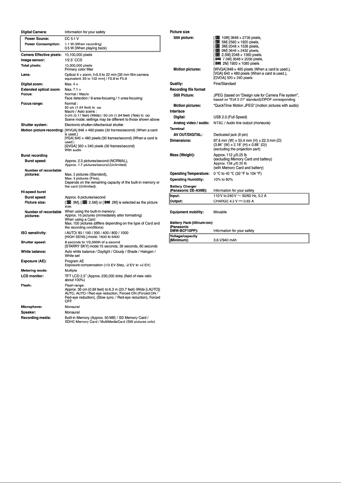
TABLE OF CONTENTS
1 SERVICE NAVIGATION------------------------------------------3
1.1. INTRODUCTION-------------------------------------------3
1.2. Important Notice 1:(Other than U.S.A. and
Canadian Market)------------------------------------------3
2 INITIAL SETTINGS:-----------------------------------------------4
3DIAGRAMS----------------------------------------------------------7
3.1. Overall Block Diagram------------------------------------7
3.2. CCD Flex Schematic Diagram--------------------------8
4 REPLACEMENT PARTS LIST ---------------------------------9
4.1. Frame & Casing Section -------------------------------10
4.2. Packing & Accessories Section (1)------------------ 11
4.3. Packing & Accessories Section (2)------------------13
PAGE PAGE
2

1 SERVICE NAVIGATION
1.1. INTRODUCTION
This Service Manual contains technical information which will help service personnel to understand and service the Digital Camera
Digital Camera; DMC-FS42 series.
The Digital Camera DMC-FS4 series have been developed based on DMC-FS4 series.
Since this Service Manual does not cover the same part which is already described in the Service Manual for DMC-FS4 series,
when servicing, refer to the descriptions in the Service Manual for; DMC-FS4P/PC/PR/PU/EB/EE/EF/EG/EP/GC/GJ/GK/GN,
Order No.DSC0903022CE (Service Manual Vol. 1).
1.2. Important Notice 1:(Other than U.S.A. and Canadian Market)
When a part replacement is required for repairing MAIN PCB and/or SUB PCB, replace as an assembled parts.
The following category is/are recycle module part. please send it/them to Central Repair Center.
MAIN PCB : VEP56074D
3
2 INITIAL SETTINGS:
After replacing the MAIN PCB, be sure to perform the initial settings after achieving the adjustment by ordering the following
procedure in accordance with model suffix of the unit.
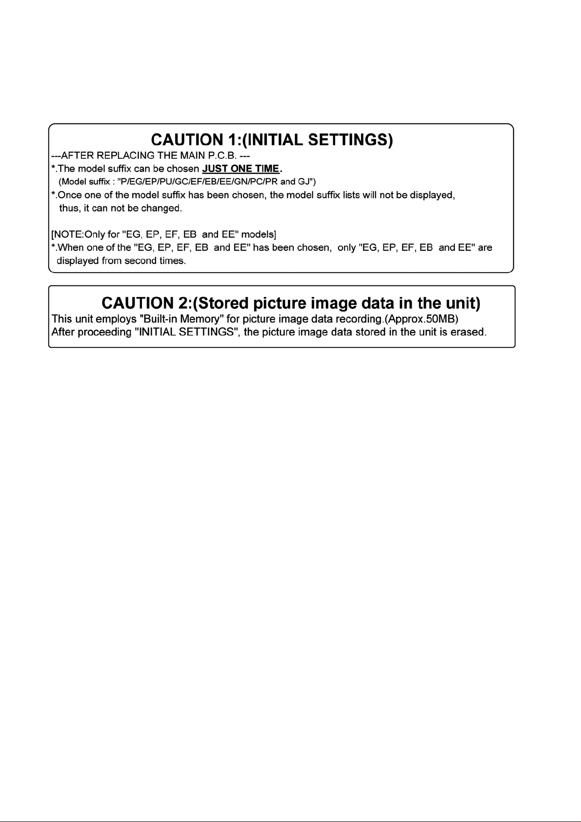
1. IMPORTANT NOTICE:
Before proceeding Initial settings, be sure to read the following CAUTIONS.
2. PROCEDURES:
• Precautions: Read the above “CAUTION 1” and “CAUTION 2”, carefully.
• Preparation:
1. Attach the Battery or AC Adaptor with a DC coupler to the unit.
2. Set the recording mode to the [NORMAL PICTURE] mode.
(Press the [MODE] button and select the [NORMAL PICTURE] by pressing the “[ UP ] and [DOWN] of Cursor buttons”,
then press the [MENU/SET] button.)
NOTE:
If the unit is other than [NORMAL PICTURE] mode, it does not display the initial settings menu.
• Step 1. The temporary cancellation of “INITIAL SETTINGS”:
Set the [REC]/[PLAYBACK] selector switch to “[ REC ] (Camera mark)”.
While keep pressing “[ UP ] of Cursor button” and [ DISPLAY ] button simultaneously, turn the Power on.
• Step 2. The cancellation of “INITIAL SETTINGS”:
Set the [REC]/[PLAYBACK] selector switch to “[ PLAYBACK ]”.
Press “[ UP ] of Cursor button” and [ DISPLAY ] button simultaneously, then turn the Power off.
• Step 3. Turn the Power on:
Set the [REC]/[PLAYBACK] selector switch to “[ REC ] (Camera mark)”, and then turn the Power on.
• Step 4. Display the INITIAL SETTING:
NOTE:
If the unit is other than [NORMAL PICTURE] mode, it does not display the initial settings menu.
While keep pressing [ MENU/SET ] and “[ RIGHT ] of Cursor buttons” simultaneously, turn the Power off.
The “INITIAL SETTINGS” menu is displayed.
There are two kinds of “INITIAL SETTINGS” menu form as follows:
4
[CASE 1. After replacing MAIN P.C.B.]
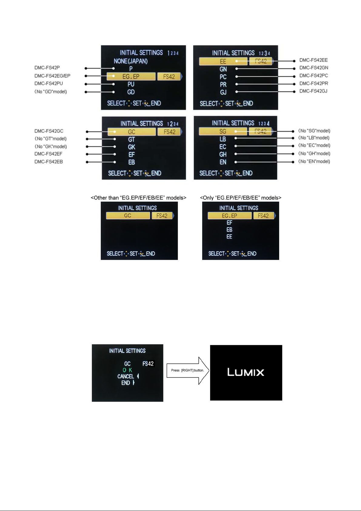
When MAIN P.C.B. has just been replaced, all of the model suffix is displayed as follows. (Four pages in total)
[CASE 2. Other than “After replacing MAIN P.C.B.”]
• Step 5. Choose the model suffix in “INITIAL SETTINGS”: (Refer to “CAUTION 1”)
[Caution: After replacing MAIN P.C.B.]
The model suffix can been chosen, JUST ONE TIME
Once one of the model suffix have been chosen, the model suffix lists will not be displayed, thus, it can be changed.
Therefore, select the area carefully.
Select the area with pressing “[ UP ] / [ DOWN ] of Cursor buttons”.
• Step 6. Set the model suffix in “INITIAL SETTINGS”:
Press the “[ RIGHT ] of Cursor buttons”.
The only set area is displayed, and then press the “[ RIGHT ] of Cursor buttons” after confirmation.
(The unit is powered off automatically.)
5
 Loading...