

Panasonic DMR-E500HS, DMRE500 - DVD RECORDER DECK, DMRE500H - DVD RECORDER DECK, DMRE500HP - DVD RECORDER DECK, DMRE500HPP Operating Instructions Manual
...
HDD DVD SD PC
Operating Instructions
DVD Video Recorder
Model No. DMR-E500H
Dear customer
Thank you for purchasing this product. For optimum performance
and safety, please read these instructions carefully.
Before connecting, operating or adjusting this product, please read
these instructions completely.
Please keep this manual for future reference.
Region number supported by this unit
Region numbers are allocated to DVD players and software
according to where they are sold.
≥The region number of this unit is “1”.
≥The unit will play DVDs marked with labels containing “1” or
“ALL”.
Example:
1
PP
ALL
[For\U.S.A.]only]
The warranty can be found on page 80.
[For\Canada]only]
The warranty can be found on page 81.
La referencia rápida en español se puede encontrar
en la página 82.
1
2
4
This manual was printed with soy based ink.
RQT7394-2P

CAUTION!
THIS PRODUCT UTILIZES A LASER.
USE OF CONTROLS OR ADJUSTMENTS OR PERFORMANCE
OF PROCEDURES OTHER THAN THOSE SPECIFIED HEREIN
MAY RESULT IN HAZARDOUS RADIATION EXPOSURE.
DO NOT OPEN COVERS AND DO NOT REPAIR YOURSELF.
REFER SERVICING TO QUALIFIED PERSONNEL.
WARNING:
TO REDUCE THE RISK OF FIRE, ELECTRIC
SHOCK OR PRODUCT DAMAGE, DO NOT
EXPOSE THIS APPARATUS TO RAIN, MOISTURE,
DRIPPING OR SPLASHING AND THAT NO
OBJECTS FILLED WITH LIQUIDS, SUCH AS
VASES, SHALL BE PLACED ON THE APPARATUS.
Getting started
Keep the small memory cards such as the SD
Memory Card out of reach of children. If
swallowed, seek medical advice immediately.
-
VISIBLE AND INVISIBLE LASER RADIATION WHEN OPEN.
DANGER
AVOID DIRECT EXPOSURE TO BEAM.
-
VISIBLE AND INVISIBLE LASER RADIATION WHEN OPEN.
CAUTION
AVOID EXPOSURE TO BEAM.
-
RAYONNEMENT LASER VISIBLE ET INVISIBLE EN CAS D’OUVERTURE.
ATTENTION
EXPOSITION DANGEREUSE AU FAISCEAU.
-
SYNLIG OG USYNLIG LASERSTRÅLING VED ÅBNING.
ADVARSEL
UNDGÅ UDSÆTTELSE FOR STRÅLING.
-
AVATTAESSA OLET ALTTIINA NÄKYVÄÄ JA NÄKYMÄTÖN
VARO !
LASERSÄTEILYLLE. ÄLÄ KATSO SÄTEESEEN.
-
SYNLIG OCH OSYNLIG LASERSTRÅLNING NÄR DENNA DEL
VARNING
ÄR ÖPPNAD. BETRAKTA EJ STRÅLEN.
-
SYNLIG OG USYNLIG LASERSTRÅLING NÅR DEKSEL ÅPNES.
ADVARSEL
UNNGÅ EKSPONERING FOR STRÅLEN.
-
SICHTBARE UND UNSICHTBARE LASERSTRAHLUNG, WENN ABDECKUNG
VORSICHT
GEÖFFNET. NICHT DEM STRAHL AUSSETZEN.
-
-
(FDA 21 CFR)
(IEC60825-1)
RQLS0233
(Inside of product)
CAUTION
RISK OF ELECTRIC SHOCK
DO NOT OPEN
CAUTION: TO REDUCE THE RISK OF ELECTRIC
SHOCK, DO NOT REMOVE SCREWS.
NO USER-SERVICEABLE PARTS
INSIDE.
REFER SERVICING TO QUALIFIED
SERVICE PERSONNEL.
The lightning flash with arrowhead symbol, within
an equilateral triangle, is intended to alert the user
to the presence of uninsulated “dangerous voltage”
within the product’s enclosure that may be of sufficient magnitude to constitute a risk of electric shock
to persons.
The exclamation point within an equilateral triangle
is intended to alert the user to the presence of
important operating and maintenance (servicing)
instructions in the literature accompanying the appliance.
CAUTION!
DO NOT INSTALL OR PLACE THIS UNIT IN A BOOKCASE,
BUILT-IN CABINET OR IN ANOTHER CONFINED SPACE.
ENSURE THE UNIT IS WELL VENTILATED. TO PREVENT
RISK OF ELECTRIC SHOCK OR FIRE HAZARD DUE TO
OVERHEATING, ENSURE THAT CURTAINS AND ANY OTHER
MATERIALS DO NOT OBSTRUCT THE VENTILATION VENTS.
THE FOLLOWING APPLIES ONLY IN THE U.S.A.
Note to CATV system installer:
This reminder is provided to call the CATV system installer’s
attention to Article 820-40 of the NEC that provides guidelines for
proper grounding and, in particular, specifies that the cable ground
shall be connected to the grounding system of the building, as
close to the point of cable entry as practical.
The socket outlet shall be installed near the equipment and
easily accessible or the mains plug or an appliance coupler shall
remain readily operable.
THE FOLLOWING APPLIES ONLY IN THE U.S.A.
FCC Note:
This equipment has been tested and found to comply with the
limits for a Class B digital device, pursuant to Part 15 of the FCC
Rules. These limits are designed to provide reasonable protection
against harmful interference in a residential installation. This
equipment generates, uses, and can radiate radio frequency
energy and, if not installed and used in accordance with the
instructions, may cause harmful interference to radio
communications. However, there is no guarantee that interference
will not occur in a particular installation. If this equipment does
cause harmful interference to radio or television reception, which
can be determined by turning the equipment off and on, the user
is encouraged to try to correct the interference by one or more of
the following measures:
≥Reorient or relocate the receiving antenna.
≥Increase the separation between the equipment and receiver.
≥Connect the equipment into an outlet on a circuit different from
that to which the receiver is connected.
≥Consult the dealer or an experienced radio/TV technician for
help.
FCC Caution: To assure continued compliance, follow the
attached installation instructions and use only shielded interface
cables when connecting to peripheral devices.
Any changes or modifications not expressly approved by the party
responsible for compliance could void the user’s authority to
operate this equipment.
This device complies with Part 15 of the FCC Rules. Operation is
subject to the following two conditions: (1) This device may not
cause harmful interference, and (2) this device must accept any
interference received, including interference that may cause
undesired operation.
Responsible Party:
Panasonic Corporation of North America
One Panasonic Way
Secaucus, NJ, 07094 USA
Telephone No.: 1-800-211-7262
IMPORTANT SAFETY INSTRUCTIONS
Read these operating instructions carefully before using the unit. Follow the safety instructions on the unit and the applicable safety instructions
listed below. Keep these operating instructions handy for future reference.
1) Read these instructions.
2) Keep these instructions.
3) Heed all warnings.
4) Follow all instructions.
5) Do not use this apparatus near water.
6) Clean only with dry cloth.
7) Do not block any ventilation openings. Install in accordance with
the manufacturer’s instructions.
8) Do not install near any heat sources such as radiators, heat
registers, stoves, or other apparatus (including amplifiers) that
produce heat.
9) Do not defeat the safety purpose of the polarized or groundingtype plug. A polarized plug has two blades with one wider than
the other. A grounding-type plug has two blades and a third
grounding prong. The wide blade or the third prong are
provided for your safety. If the provided plug does not fit into
RQT7394
2
your outlet, consult an electrician for replacement of the
obsolete outlet.
10) Protect the power cord from being walked on or pinched
particularly at plugs, convenience receptacles, and the point
where they exit from the apparatus.
11) Only use attachments/accessories specified by the
manufacturer.
12) Use only with the cart, stand, tripod, bracket, or
table specified by the manufacturer, or sold with
the apparatus. When a cart is used, use caution
when moving the cart/apparatus combination to
avoid injury from tip-over.
13) Unplug this apparatus during lightning storms or
when unused for long periods of time.
14) Refer all servicing to qualified service personnel. Servicing is
required when the apparatus has been damaged in any way,
such as power-supply cord or plug is damaged, liquid has been
spilled or objects have fallen into the apparatus, the apparatus
has been exposed to rain or moisture, does not operate
normally, or has been dropped.

Table of contents
Getting started
IMPORTANT SAFETY INSTRUCTIONS . . . . . . . . . . . . . . .2
Accessories. . . . . . . . . . . . . . . . . . . . . . . . . . . . . . . . . . . . .3
Useful features . . . . . . . . . . . . . . . . . . . . . . . . . . . . . . . . . .4
The remote control. . . . . . . . . . . . . . . . . . . . . . . . . . . . . . .4
Control reference guide . . . . . . . . . . . . . . . . . . . . . . . . . . .5
STEP 1
STEP 2
Connection . . . . . . . . . . . . . . . . . . . . . . . . . . . . . .6
Connections for the Network function . . . . . . . . . . . . . . . . . . . 10
Connecting a LAN cable to this unit. . . . . . . . . . . . . . . . . . . . . 11
Setting up the TV Guide On ScreenTM
system . . . . . . . . . . . . . . . . . . . . . . . . . . . . . . . . . . . . . . .12
STEP 3
Set up to match your television and
remote control . . . . . . . . . . . . . . . . . . . . . . . . . . . . . . . .14
STEP 4
STEP 5
Multi-channel speaker setting . . . . . . . . . . . . . .15
Setting up the Network . . . . . . . . . . . . . . . . . . .16
This unit’s network setting . . . . . . . . . . . . . . . . . . . . . . . . . . . . 16
When more than one network compatible Panasonic DVD
recorder is on the Home Network . . . . . . . . . . . . . . . . . . . . . 17
To be able to operate this unit from a computer on the Home
Network. . . . . . . . . . . . . . . . . . . . . . . . . . . . . . . . . . . . . . . . . 18
HDD, disc and card information . . . . . . . . . . . . . . . . . . .20
Recording
Recording television programs. . . . . . . . . . . . . . . . . . . .22
Recording modes and approximate recording times . . . . . . . . 23
Selecting audio to record . . . . . . . . . . . . . . . . . . . . . . . . . . . . . 23
Playing while you are recording . . . . . . . . . . . . . . . . . . . . . . . . 24
Flexible Recording. . . . . . . . . . . . . . . . . . . . . . . . . . . . . . . . . . 24
Timer recording . . . . . . . . . . . . . . . . . . . . . . . . . . . . . . . .25
Using the TV Guide On ScreenTM system to make timer recordings
Manually programming timer recordings . . . . . . . . . . . . . . . . . 26
Using VCR Plusi system to make timer recordings. . . . . . . . 26
Check, change or delete a program. . . . . . . . . . . . . . . . . . . . . 27
. . 25
Utilizing the TV Guide On ScreenTM system. . . . . . . . . .28
Playing back
Playing recorded video contents/
Playing play-only discs . . . . . . . . . . . . . . . . . . . . . . . . .30
Operations during play. . . . . . . . . . . . . . . . . . . . . . . . . . . . . . . 31
Editing operations during play . . . . . . . . . . . . . . . . . . . . . . . . . 32
Changing audio during play . . . . . . . . . . . . . . . . . . . . . . . . . . . 32
Using menus to play MP3 . . . . . . . . . . . . . . . . . . . . . . . .33
Playing still pictures. . . . . . . . . . . . . . . . . . . . . . . . . . . . .34
Useful functions during still picture play. . . . . . . . . . . . . . . . . . 35
Playing MPEG4 titles . . . . . . . . . . . . . . . . . . . . . . . . . . . .36
Useful functions during MPEG4 title play. . . . . . . . . . . . . . . . . 37
Using on-screen menus and Status messages. . . . . . .38
On-screen menus . . . . . . . . . . . . . . . . . . . . . . . . . . . . . . . . . . 38
Status messages . . . . . . . . . . . . . . . . . . . . . . . . . . . . . . . . . . . 39
FUNCTIONS window. . . . . . . . . . . . . . . . . . . . . . . . . . . . . . . . 39
Editing
Editing titles/chapters . . . . . . . . . . . . . . . . . . . . . . . . . . .40
Editing titles/chapters and playing chapters. . . . . . . . . . . . . . . 40
Title operations . . . . . . . . . . . . . . . . . . . . . . . . . . . . . . . . . . . . 41
Chapter operations . . . . . . . . . . . . . . . . . . . . . . . . . . . . . . . . . 41
Creating, editing and playing play lists . . . . . . . . . . . . .42
Creating play lists. . . . . . . . . . . . . . . . . . . . . . . . . . . . . . . . . . . 42
Editing and playing play lists/chapters. . . . . . . . . . . . . . . . . . . 43
Play list operations. . . . . . . . . . . . . . . . . . . . . . . . . . . . . . . . . . 43
Chapter operations . . . . . . . . . . . . . . . . . . . . . . . . . . . . . . . . . 43
Editing still pictures . . . . . . . . . . . . . . . . . . . . . . . . . . . . .44
Picture and folder operation. . . . . . . . . . . . . . . . . . . . . . . . . . . 44
Editing MPEG4 titles. . . . . . . . . . . . . . . . . . . . . . . . . . . . .45
MPEG4 title operations . . . . . . . . . . . . . . . . . . . . . . . . . . . . . . 45
Entering text . . . . . . . . . . . . . . . . . . . . . . . . . . . . . . . . . . .46
Transfer (Dubbing)
Transferring (dubbing) titles or play lists . . . . . . . . . . . 47
One Touch Transfer (dubbing) . . . . . . . . . . . . . . . . . . . . . . . . . 48
Transferring (dubbing) using the transferring (dubbing) list . . . 48
Transferring (dubbing) a finalized DVD-R . . . . . . . . . . . . . . . . . 50
Recording from a video cassette recorder. . . . . . . . . . 51
Manual recording . . . . . . . . . . . . . . . . . . . . . . . . . . . . . . . . . . . 51
DV automatic recording (DV AUTO REC). . . . . . . . . . . . . . . . . 51
Transferring (dubbing) still pictures . . . . . . . . . . . . . . . 52
Transferring (dubbing) using the transferring (dubbing) list . . . 52
Transferring (dubbing) all the still pictures on a card
—COPY ALL PICTURES. . . . . . . . . . . . . . . . . . . . . . . . . . . . 53
Transferring (dubbing) MPEG4/MPEG2 titles. . . . . . . . 54
One Touch transfer (dubbing). . . . . . . . . . . . . . . . . . . . . . . . . . 54
Transferring (dubbing) using the transferring (dubbing) list . . . 55
Network
Operating the DVD recorder by computer . . . . . . . . . . 56
Playing back video titles recorded on another DVD
recorder’s HDD . . . . . . . . . . . . . . . . . . . . . . . . . . . . . . . 57
Convenient functions
HDD, disc and card setting . . . . . . . . . . . . . . . . . . . . . . 58
Setting the protection . . . . . . . . . . . . . . . . . . . . . . . . . . . . . . . . 58
Providing a disc with a name . . . . . . . . . . . . . . . . . . . . . . . . . . 58
Erasing all titles, play lists and MPEG4 titles—Erase all titles
Erasing all the contents of a disc or card—Format . . . . . . . . . . 59
Enabling DVD-R to be played on other equipment—Finalize . . 60
. . . 59
Changing the unit’s settings . . . . . . . . . . . . . . . . . . . . . 61
Common procedures . . . . . . . . . . . . . . . . . . . . . . . . . . . . . . . . 61
Summary of settings. . . . . . . . . . . . . . . . . . . . . . . . . . . . . . . . . 61
Channel/Clock settings when TV Guide On ScreenTM
system is not used . . . . . . . . . . . . . . . . . . . . . . . . . . . . 65
Auto channel/clock settings . . . . . . . . . . . . . . . . . . . . . . . . . . . 65
Channel captions . . . . . . . . . . . . . . . . . . . . . . . . . . . . . . . . . . . 66
Reference
Specifications . . . . . . . . . . . . . . . . . . . . . . . . . . . . . . . . . 67
Glossary. . . . . . . . . . . . . . . . . . . . . . . . . . . . . . . . . . . . . . 68
Frequently asked questions . . . . . . . . . . . . . . . . . . . . . 70
Error messages. . . . . . . . . . . . . . . . . . . . . . . . . . . . . . . . 72
Troubleshooting guide . . . . . . . . . . . . . . . . . . . . . . . . . . 73
Product Service. . . . . . . . . . . . . . . . . . . . . . . . . . . . . . . . 78
Maintenance/HDD, disc and card handling . . . . . . . . . 79
Limited Warranty (ONLY FOR U.S.A.) . . . . . . . . . . . . . . 80
Limited Warranty (ONLY FOR CANADA). . . . . . . . . . . . 81
Guía de referencia rápida en español
(Spanish Quick Reference)
Index . . . . . . . . . . . . . . . . . . . . . . . . . . . . . . . . . Backcover
. . . . . . . . . . . . . 82
Getting started
Accessories
Please check and identify the supplied accessories. Use numbers indicated in parentheses when asking for replacement parts.
Only for U.S.A.: To order accessories, refer to “Accessory Purchases” on page 80.
Only for Canada: To order accessories, call the dealer from whom you have made your purchase.
∏∏∏∏∏∏
1 Remote control
(EUR7721KL0)
(U.S.A. only)
Product Registration Card
Please complete and return the included product registration card, or register via the Internet at: http://www.prodreg.com/panasonic/
1 AC power supply
cord
(K2CB2CB00006)
≥
For use with this unit
only. Do not use it
with other equipment.
1 75 ≠ coaxial
cable
(VJA1125)
2 Batteries
for remote control
1 Audio/video
cable
(K2KA6CA00001)
1 IR Blaster
(K2ZZ04C00002)
RQT7394
3

Useful features
This DVD Video recorder records high quality images to rapid
random access capable HDD (Hard disk drive) or DVD-RAM. This
has resulted in many new features that outperform older tape
formats. The following information summarizes a few of these
features.
Instant recording
You no longer need to search for empty disc space. By pressing the
recording button, the unit finds available recording space and begins
recording right away. There is no need to worry about overwriting
already recorded content.
HDD recording
You can keep on recording your favorite programs to an internal HDD
that is able to record up to 709 hours when using EP (8H) mode.
Getting started
You can also high speed transfer (dub) your favorite programs to
DVD-RAM or DVD-R and create a backup disc.
LAN terminal, SD/PC card slots, DV input terminal
This unit is equipped with interfaces that allow networking with digital
equipment.
≥The LAN terminal of this unit lets you connect to a computer for
easy text input when giving names to video titles. This also allows
playback of MPEG4 titles and viewing of JPEG. You can also
connect to another network compatible Panasonic DVD recorder
for more video playback choice.
≥The SD/PC card slots of this unit let you transfer (dub) digital
camera photographs from a card to DVD-RAM for easy storage
without using a computer.
≥The DV automatic recording function of this unit lets you easily
transfer (dub) digital images to the HDD by connecting only a
single DV cable.
Transferring (dubbing)/editing/playing MPEG4 titles
≥While recording programs to the HDD you can simultaneously
record them as MPEG4 titles. By then transferring (dubbing) these
MPEG4 titles from the HDD to a SD Memory Card or
MultiMediaCard, you can view them on a SD Video Camera etc.
≥You can also transfer (dub) MPEG2 titles recorded on a SD Video
Camera etc, to HDD or DVD-RAM.
TV Guide On ScreenTM system
The TV Guide On ScreenTM system provides a handy electronic
program guide (EPG) for checking what’s on. Setting up to record a
broadcast is easy too. Simply select the desired program from the
displayed list. You can also search for desired programs alphabetically
or by displaying only the programs in a certain category.
≥This service may not be available in some areas.
Instant play
There is no need to rewind or search forward. Direct Navigator
guides you to the beginning of the recorded video immediately.
Chasing playback
There is no need to wait until recording is
complete. Without stopping recording, you can
play the video currently being recorded from its
beginning.
Simultaneous Recording and Playback
While recording, you can play another video
program that was recorded previously.
Time Slip
During play and also while recording, you can
jump to the scene you wish to view by specifying
the skip time.
5.1 channel surround sound
Enjoy the powerful movie theater and hall-like sound available with
multiple channel audio found on DVDs by connecting an amplifier
and speakers.
The remote control
∫ Batteries
R6/LR6, AA, UM-3
≥Insert so the poles (i and j) match those in the remote control.
≥Do not use rechargeable type batteries.
≥Do not mix old and new batteries.
≥Do not use different types at the same time.
≥Do not heat or expose to flame.
≥Do not take apart or short circuit.
≥Do not attempt to recharge alkaline or manganese batteries.
≥Do not use batteries if the covering has been peeled off.
Mishandling of batteries can cause electrolyte leakage which can
damage items the fluid contacts and may cause a fire.
Remove if the remote control is not going to be used for a long
period of time. Store in a cool, dark place.
[Note]
If you cannot operate the unit or television using the remote control
after changing the batteries, please re-enter the codes (➡ page 14).
∫ Use
Remote control signal sensor
20
30
20
30
7 m (23 feet) directly in front of the unit
The manufacturer accepts no responsibility and offers no compensation for loss of recorded or edited material due to a problem
with the unit or recordable media, and accepts no responsibility and offers no compensation for any subsequent damage caused by
such loss.
Examples of causes of such losses are
≥A disc recorded and edited with this unit is played in a DVD recorder or computer disc drive manufactured by another company.
RQT7394
≥A disc used as described above and then played again in this unit.
≥A disc recorded and edited with a DVD recorder or computer disc drive manufactured by another company is played in this unit.
4

Control reference guide
Í
EXT
Link
REC
PLAY
DVD
D
.MIX
R-AM
REC
EXT
Link
REC
PLAY
EXT
Link
REC
PLAY
Remote control
Turn the unit on (➡ page 12)
Input select (L1, L2, L3 or DV) (➡ page 51)
Select channels and title numbers, etc./
Basic operations for recording and play
Show Top menu/Direct Navigator
Show sub menu (➡ page 40)
Show on-screen menu (➡ page 38)
Show timer recording schedule
Erase items (➡ page 32)
Show SETUP menu (➡ page 13, 61)
Changing the size of information window
One touch transfer (dubbing)/“Blue” button for
television program list (➡ page 48, 25)
Enter numbers
Cancel
(➡ page 30, 40)
(➡ page 26)
(➡ page 28)
DVD POWER
TV
POWER
TV/VIDEO
INPUT SELECT
HDD
DVD
1
23
456
7809
CANCEL
SKIP
STOP
DIRECT NAVIGATOR
TOP MENU
SUB MENU
PROG/CHECK
DISPLAY
SETUP
Info
DUBBING
CH
VCR Plus+
SLOW/SEARCH
PAU S E
ENTER
TIME SLIP
REC MODEERASE
CHAPTER
VOLUME
SD/PC
PAG E
CH
AUDI O
CM SKIP
PLAY/x1.3
FUNCTIONS
RETURN
TV GUIDE
REC
STATUS
Television operations (➡ page 14)
Select drive (HDD, DVD, SD or PC)
(➡ page 22, 30, 35)
Channel select (➡ page 22)
Select audio (➡ page 23, 32)/Adjust the audio
recording level (➡ page 51)
Skip a minute forward (➡ page 31)
Show VCR Plusr screen (➡ page 26)
Show FUNCTIONS window (➡ page 39)
Selection/Enter, Frame-by-frame (➡ page 12, 31)
Return to previous screen
Skip the specified time/Display the television image
as a picture-in-picture (➡ page 24, 31)
Show television program list (➡ page 25)
Change recording mode (➡ page 22)
Start recording (➡ page 23)
Show status messages (➡ page 39)
Create chapters/“Green” button for television program
list (➡ page 32, 25)
Getting started
Main unit
POWER button (POWER
Press to switch the unit from on to standby mode or
vice versa. In standby mode, the unit is still
consuming a small amount of power.
SD/PC card slots (➡ page 34)
POWER
POWER
SD CARD
S-VIDEO IN
L2
Connection for camcorder, etc. (➡ page 51)
Connection for digital video
(DV) camcorder (➡ page 51)
Rear panel terminals (➡ page 7)
/I) (➡ page 12)
Disc tray (➡ page 22, 30)
PC CARD
L/MONO
VIDEO IN
R
AUDIO IN
DV IN
Lights when the HDD or DVD
drive is selected
The unit’s display
HDD/Card indicator
MPEG4 indicator
When lit: Simultaneous MPEG4
recording function is
activated (➡ page 22).
e.g.,
[HDD]
HDD
SD PC
MPEG4
REC
PLAY
Recording
EJECT
HDD
Skip the specified time/Display the television image
Recording mode
Timer recording indicator
XP
SP
LP
CH
EP
Channel
Playback
Select drive (➡ page 22, 30, 35)
Lights when the HDD, DVD, SD or PC
Remote control signal sensor/
Open/close disc tray (➡ page 22, 30)
DVD
Display (➡ below)
Time Slip indicator (➡ page 24)
as a picture-in-picture (➡ page 24, 31)
Channel select (➡ page 22)
Start recording (➡ page 23)
Transferring (dubbing)/Network function indicator
DVD
R-AM
VCD
REC
PLAY
Main display section
Recording/Playback
Stop (➡ page 23, 31)
drive is selected
OPEN/CLOSE
TIME SLIP
HDD DVD SD PC
TIME SLIP
DRIVE SELECT
REC
CH
Skip/Slow/Search
Disc type
.MIX
D.MIX (multi-channel DVD-Audio only)
When lit: Down-mixing (➡ page 68) is
possible.
When off: The disc prevents down-mixing
(➡ page 20, Regarding DVDAudio).
Start play
(➡ page 30)
/x
1.3
(➡ page 31)
RQT7394
5

STEP
1
Connection
∫ Examples of equipment you can connect to this unit’s terminals
Te le v is i on
Amplifier
Computer or other network
Getting started
From OUT1 or OUT2
terminals
To IN3 (L3) input
terminals (rear)
From AUDIO OUT terminals or
DIGITAL AUDIO OUT terminal
This unit
To L2 or DV input terminals
(front) (➡ page 51)
To IN1 (L1) input
terminals (rear)
Via the LAN terminal
compatible Panasonic DVD
recorder
Video cassette recorder
Cable TV box
Do not place the unit on
amplifiers or equipment
that may become hot.
The heat can damage the unit.
Before moving the unit, ensure the disc tray is empty.
Failure to do so will risk severely damaging the disc and the
unit.
Camcorder
∫ When the unit is not to be used for a long time
To save power, unplug it from the household AC outlet. This unit
consumes a small amount of power, even when it is turned off
(approx. 21 W).
≥Note that the television program list is not downloaded while the
unit is unplugged.
RQT7394
6
≥The equipment connections described are examples.
≥Before connection, turn off all equipment and read the appropriate operating instructions.
≥Peripheral equipment and optional cables sold separately unless otherwise indicated.
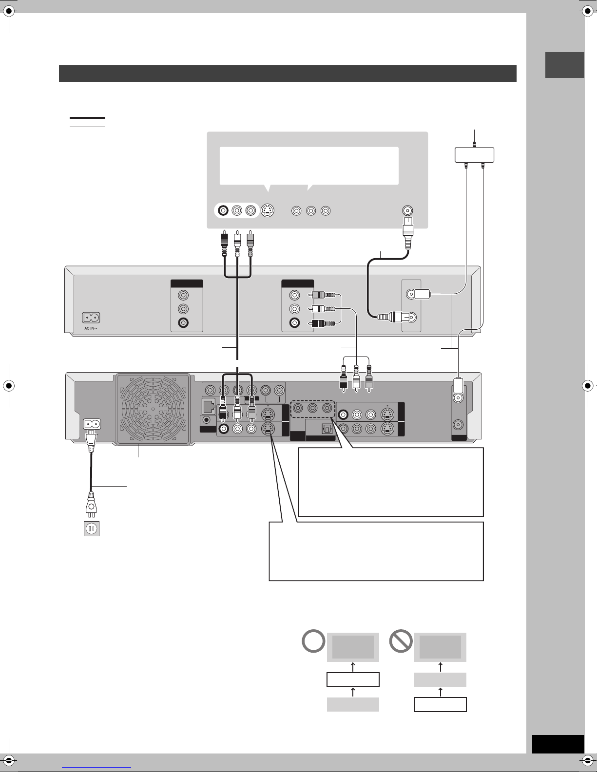
Connection with a television and video cassette recorder
The connection will allow the video cassette recorder to be used for playback when this unit is turned off. For optimum operation, it is
recommended that this unit be connected as shown below.
A to R are indexes for Spanish Quick Reference.
A
indicates included accessories.
indicates accessories not included.
D Cable from wall or antenna signal
B Television
C When connecting using these terminals, ensure
you connect the audio cables to the corresponding
audio input terminals on the television.
E Splitter
Getting started
G Video cassette recorder
J Audio/Video cable
K This unit
L To OUT1 or OUT2
N Cooling fan
O AC power supply cord
Connect only after all other
connections are complete.
VIDEO
AUDIO
AUDIO
F
IN
L
R
F
SUB WOOFER
G-LINK
AUDI O IN
VIDEO IN
R L
Red White Yellow
I Ye ll o w
Red White Yellow
CENTER
R - SURROUND - L
AUDIO OUT
R - AUDIO - L
VIDEO
5.1ch
S-VIDEO
jLAN (10/100)
S VIDEO IN
COMPONENT
VIDEO IN
H 75 ≠ coaxial cable
OUTIN
VIDEO
OUT
White
Red
AUDIO
AUDIO
L
R
J Audio/Video cable
M To IN1 (L1)
RL
FRONT
OUT1 OUT2
YPB PR
OPTICAL
COMPONENT
VIDEO OUT
DIGITAL AUDIO OUT
(480p/480i)
(PCM/BITSTREAM)
COMPONENT VIDEO OUT terminal
Q
Connect to COMPONENT VIDEO IN terminals on
the television through a component video cable.
These terminals can be used for either interlace or
progressive output (➡ page 69) and provide a purer
picture than the S-VIDEO OUT terminal.
≥Connect to terminals of the same color.
F
Red White Yellow
R - AUDIO - L
VHF/UHF
RF IN
VHF/UHF
RF IN
VHF/UHF
RF OUT
H 75 ≠ coaxial cable
S-VIDEO
IN1 (L1)
IN3 (L3)
VIDEO
RF IN
RF OUT
VHF/UHF
P To household AC outlet
(AC 120 V, 60 Hz)
∫ The unit’s RF OUT terminal
The picture and sound signal from this unit does not go through the
RF OUT terminal to the television.
Make sure you connect one of the following terminals on this unit to
the television: the AUDIO/VIDEO OUT terminal, the S-VIDEO OUT
terminal or the COMPONENT VIDEO OUT terminal. If the
television has none of these terminals, consult your local dealer.
≥Refer to page 9 if the antenna connector doesn’t match.
S-VIDEO OUT terminal
R
Connect to S-VIDEO IN terminal on the television through
a S-Video cable.
The S-VIDEO OUT terminal achieves a more vivid picture
than the VIDEO OUT terminal. (Actual results depend on
the television.)
Do not connect the unit through a video cassette recorder
Video signals fed through video cassette recorders will be affected
by copyright protection systems and the picture will not be shown
correctly on the television.
B Television B Television
K This unit
G VCR
G VCR
K This unit
≥When connecting to a television with a built in VCR, connect to
the input terminals on the television side, not the VCR side.
RQT7394
7

STEP
1
Connection
Connection with a cable TV box and video cassette recorder
≥You need to subscribe to a cable TV service to enjoy viewing their programming.
≥Consult your service provider regarding appropriate cable TV box.
≥If you receive your programming solely from a satellite service, the program guide in this unit will not receive program listings or
channel information. Without this information, program-based recordings cannot be made. However, recordings can still be set
manually.
The connection will allow the video cassette recorder to be used for playback when this unit is turned off. For optimum operation, it is
recommended that this unit be connected as shown below.
A to Y are indexes for Spanish Quick Reference.
Getting started
A
indicates included accessories.
indicates accessories not included.
AUDI O IN
R L
Red White Yellow
C
B Television
S VIDEO IN
VIDEO IN
COMPONENT
VIDEO IN
D Cable from wall or antenna signal
VHF/UHF
RF IN
E Splitter
F Video cassette recorder
I Audio/Video cable
J This unit
K To OUT1 or OUT2
M Cooling fan
N AC power supply cord
Connect only after all other
connections are complete.
O To household AC outlet
(AC 120 V, 60 Hz)
P IR Blaster
Insert the IR Blaster jack into the GLINK terminal.
≥Only use the included IR Blaster.
VIDEO
AUDIO
AUDIO
IN
L
R
G Yellow
White
Red
I Audio/Video cable
C
Red White Yellow
SUB WOOFER
G-LINK
CENTER
jLAN (10/100)
R - AUDIO - L
R - SURROUND - L
AUDIO OUT
5.1ch
VIDEO
RL
FRONT
S-VIDEO
I Audio/Video cable
Q These connections to IN3 (L3)
are required for the TV Guide
On Screen
TM
system to work.
T Setting the IR Blaster
➡ below
OUTIN
VIDEO
OUT
AUDIO
L
AUDIO
R
L To IN1 (L1)
YPB PR
OPTICAL
DIGITAL AUDIO OUT
(PCM/BITSTREAM)
C
OUT1 OUT2
COMPONENT
VIDEO OUT
(480p/480i)
R To IN3 (L3)
H 75 ≠ coaxial cable
H 75 ≠ coaxial cable
Red White Yellow
R - AUDIO - L
VIDEO
S-VIDEO
S Instead of using the Audio/
C
Red White Yellow
OUT
R L
VIDEO
AUDI O
S-VIDEO
VHF/UHF
RF IN
VHF/UHF
RF OUT
RF IN
IN1 (L1)
IN3 (L3)
RF OUT
VHF/UHF
video cable, you can also
connect the RF IN terminal
on this unit to the cable TV
box RF OUT terminal using
the 75 ≠ coaxial cable.
IN
RF
U Cable TV box
∫ Should I use the AUDIO/VIDEO OUT terminal or
the RF OUT terminal?
If your cable TV box has both AUDIO/VIDEO OUT terminals and
RF OUT terminals, we recommend connecting the AUDIO/VIDEO
OUT terminal with the unit’s IN3 (L3) terminal. Using this
connection provides better picture quality.
≥The S-VIDEO terminal achieves a more vivid picture than the
VIDEO terminal.
Setting the IR Blaster
Place the IR Blaster in front of the signal sensor of the cable TV box.
V Read the cable TV box operating
instructions regarding positioning of the
signal sensor.
RQT7394
8
∫ Why should I connect the IR Blaster?
The IR Blaster is a device that allows this unit to communicate with
the cable TV box. It acts like a remote control for the cable TV box.
If you connect a cable TV box to this unit, you also need to attach
the IR Blaster so this unit can control the channels on the cable TV
box.
W If necessary, use the double sided adhesive tape (included) to
secure the IR Blaster to a flat surface.
X e.g. Television stand surface
Y If you peel off the adhesive tape, the surface may become
damaged.
Once you have confirmed the cable TV box is operating
correctly, secure it by attaching the adhesive tape.
U Cable TV box

Connecting an amplifier or system component
Enjoy multi-channel surround sound on DVD by connecting an amplifier and speakers. There are two types of connection, digital and analog.
∫ Analog connection ∫ Digital connection
To enjoy multi-channel surround sound on DVD-Video and
DVD-Audio connect an amplifier using the AUDIO OUT 5.1 ch
terminals and go to the settings on page 15.
≥Switch the attenuator on if sound is distorted with this
connection (➡ page 63).
SUB-
WOOFER
CENTER
Amplifier’s rear panel
SURROUND
R L
FRONT
R L
To enjoy multi-channel surround sound on DVDVideo connect an amplifier with a built-in decoder
displaying these logo marks. Use an optical digital
audio cable and change the settings in “Digital Audio
Output” (➡ page 63).
≥You cannot use DTS Digital Surround decoders not
su ited t o DVD.
≥Even if using this connection, output will only be from 2 channels
when playing DVD-Audio.
Getting started
Red White
Audio cable
This unit
To AUDIO OUT 5.1 ch
Red White
SUB WOOFER
CENTER
jLAN (10/100)
R - AUDIO - L
G-LINK
R - SURROUND - L
AUDIO OUT
VIDEO
5.1ch
RL
S-VIDEO
Connect with AUDIO OUT1 or 2 terminals to enjoy
stereo (2 channel) sound.
If the antenna connector doesn’t match
Other antenna connections to the unit
Use one of the following connections to suit the antenna lead.
≥If your television has both lead and coaxial VHF terminals, use
the lead connection to minimize signal loss.
∫ A single twin lead
from the antenna
(Flat) Twin lead
300 ≠ cable
∫ A twin lead and a coaxial cable
from the antenna
(Flat) Twin lead 300 ≠ cable
75 ≠ coaxial cable
∫ Two twin leads
from the antenna
(Flat) Twin lead
300 ≠ cable
300–75 ≠ transformer
300–75 ≠ transformer
To this unit’s RF IN
terminal
VHF/UHF band mixer
To this unit’s RF IN
terminal(Round)
VHF/UHF band mixer
To this unit’s RF
IN terminal
FRONT
Amplifier’s rear panel
or
OPTICAL IN
Optical digital audio
cable
Do not bend sharply
Insert fully, with this
side facing up.
when connecting.
RF IN
OUT1 OUT2
COMPONENT
VIDEO OUT
(480p/480i)
YPB PR
OPTICAL
DIGITAL AUDIO OUT
(PCM/BITSTREAM)
R - AUDIO - L
VIDEO
S-VIDEO
IN1 (L1)
IN3 (L3)
RF OUT
VHF/UHF
Other antenna connections from the unit to the
television
Use one of the following connections to suit the antenna terminals
on your television. Refer to the television’s operating instructions.
∫ A twin lead and coaxial plug terminal
VHF/UHF band separator
75 ≠ coaxial cable
VHF
UHF
Te le v is i on
∫ A twin lead terminal
75–300 ≠ transformer
75 ≠ coaxial cable
Television
∫ Two twin lead terminals
VHF/UHF band separator
75 ≠ coaxial cable
Television
∫ Multiple antenna terminals
≥Connect to one of the ANT terminals, then change the television’s
settings as necessary.
Split out
ANT 1
75 ≠ coaxial cable
Te l ev i s i o n
VHF or
UHF
VHF
UHF
ANT 2
RQT7394
9
STEP
1
Connection
Connections for the Network function
≥Setting up the Network (➡ page 16–19)
≥Operations with the Network function (➡ page 56–57)
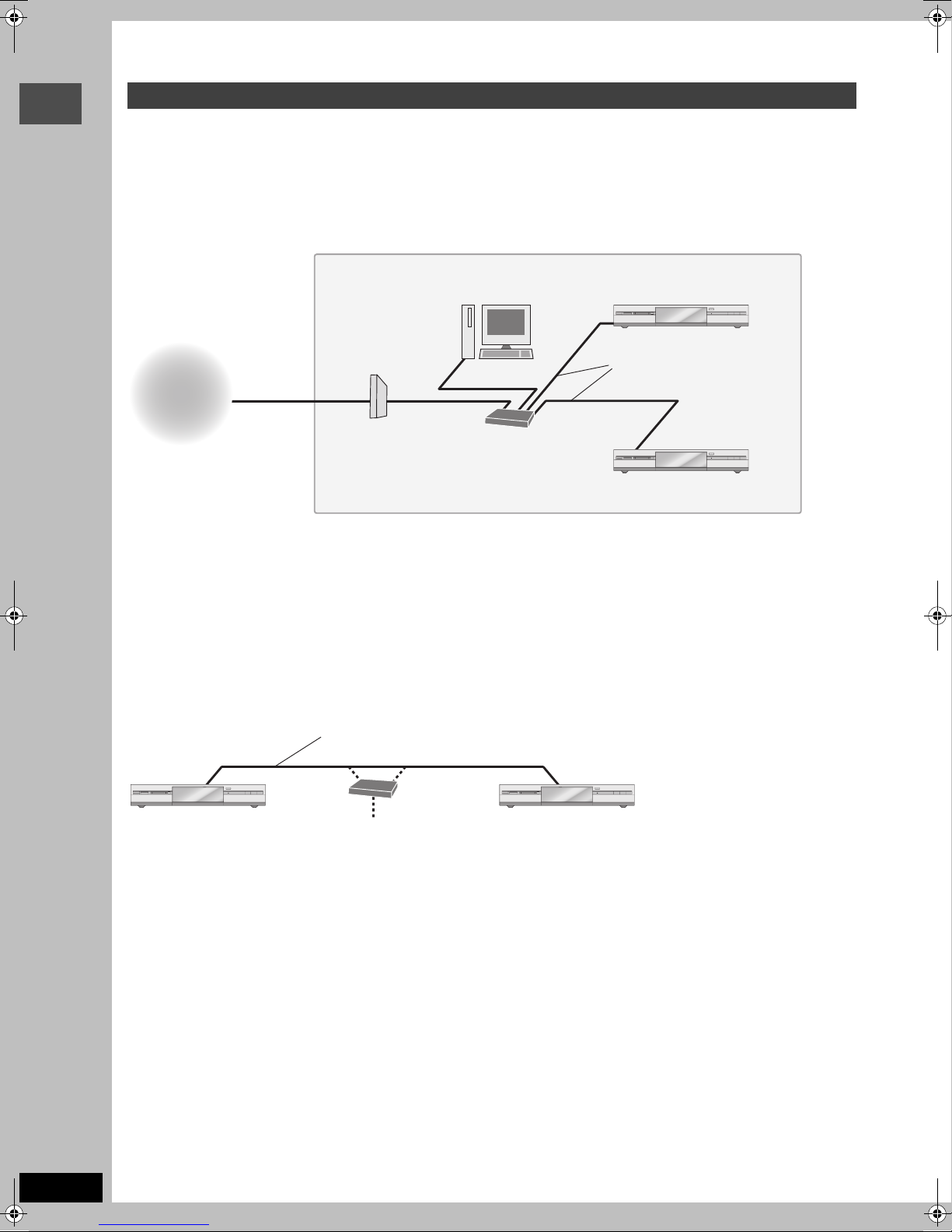
∫ Connecting to the Home Network
Connect this unit to a router on the Home Network. This will allow you to do the following:
Getting started
≥Operate this unit from a computer, i.e. give names to video titles, playback MPEG4 titles, and view JPEG.
≥Playback video stored on other network compatible Panasonic DVD recorders from this unit.
Home Network
Computer
Modem
(Cable, DSL, etc)
Internet
≥You can also connect to the network with a wireless router.
≥Set the router’s DHCP (Dynamic Host Configuration Protocol) to enable it to automatically assign IP addresses. The default configuration of
the router is normally sufficient.
≥Use a router that supports 100BASE-TX.
≥It may not be possible to connect this unit to the Internet depending upon router security settings.
Visit Panasonic’s homepage for more information about the Network function of the DVD recorder.
http://panasonic.co.jp/pavc/global/cs/dvd/index.html
≥Refer to the router’s operating instructions or contact your Internet service provider for information about router connections and settings.
Router
≥Use a hub if the modem
has a router function.
Other network compatible
Panasonic DVD recorder(s)
HDD DVD SD PC
LAN cable (not included)
≥Use category 5 cable.
HDD DVD SD PC
This unit
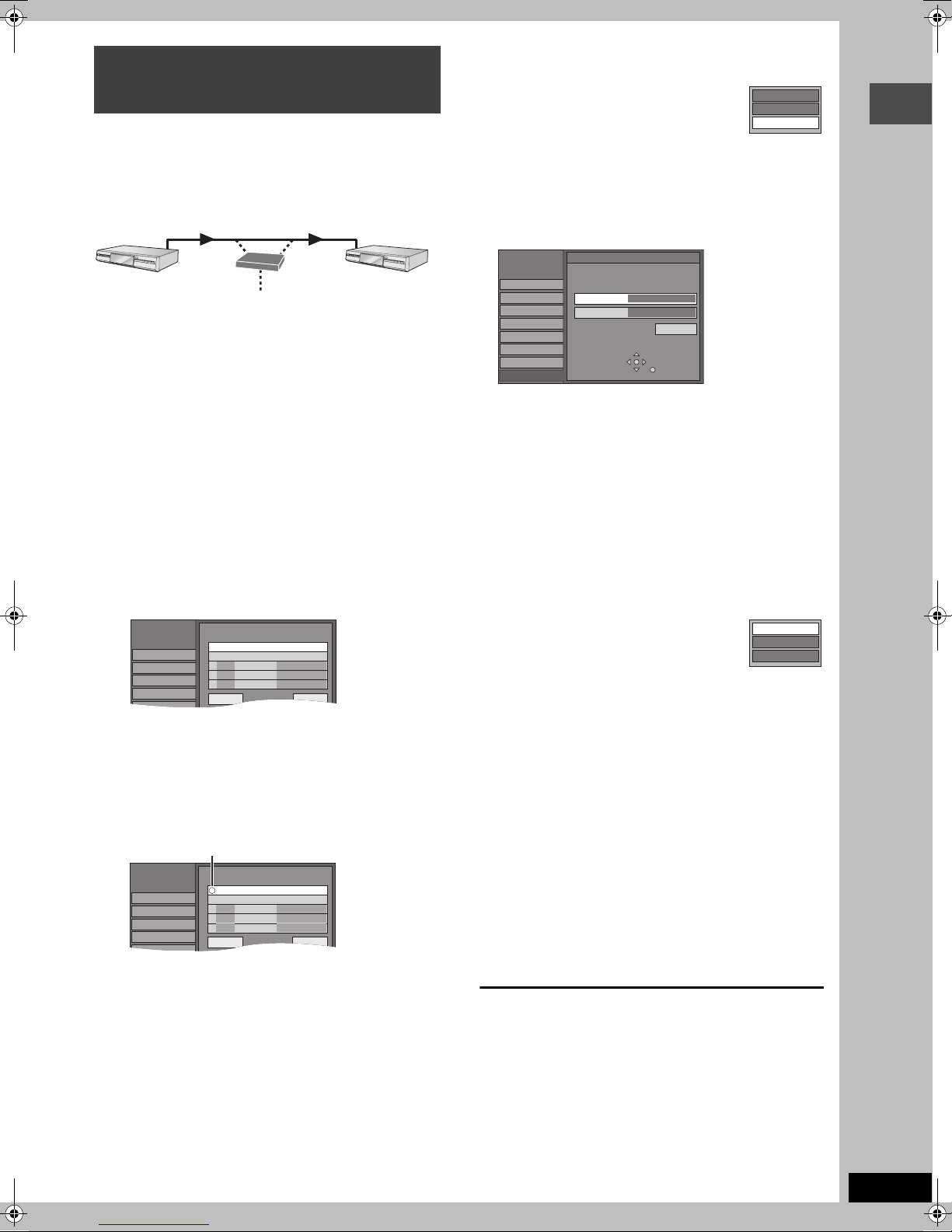
∫ Connecting directly to another network compatible Panasonic DVD recorder
Connect this unit directly to another network compatible Panasonic DVD recorder. This will allow you to playback video stored on the other
network compatible Panasonic DVD recorder from this unit.
RQT7394
10
LAN cable (not included)
≥Use category 5 cable.
HDD DVD SD PCHDD DVD SD PC
This unit Another network compatible
Router/Hub
Panasonic DVD recorder

Connecting a LAN cable to this unit
SUB WOOFER
CENTER
R - SURROUND - L
AUDIO OUT
R - AUDIO - L
VIDEO
5.1ch
jLAN (10/100)
G-LINK
LAN cable (not included)
≥Use category 5 cable.
To router, other network compatible
Panasonic DVD recorder, etc
RL
FRONT
S-VIDEO
OUT1 OUT2
COMPONENT
VIDEO OUT
(480p/480i)
YPB PR
OPTICAL
DIGITAL AUDIO OUT
(PCM/BITSTREAM)
R - AUDIO - L
The LAN terminal will have the
following marks.
e.g.,
VIDEO
S-VIDEO
IN1 (L1)
IN3 (L3)
RF IN
RF OUT
VHF/UHF
This unit
Getting started
∫ To prevent improper use
≥The unit’s network password:
–Please do not reveal your password to anyone or let it be seen
by anyone.
–Should a third party have carried out the installation and setting-
up of this unit please change the password.
–Please initialize the password before requesting any repairs
(➡ page 78).
–If transferring this unit to a third party, or throwing it away, please
initialize it.
≥We are unable to provide any technological information related to
network security.
∫ Service support
It is the customer’s responsibility to bear all essential connection
costs for this unit. These include equipment for Internet
communications (modem, router, hub etc.) and contract,
installation, set-up, connection and telecommunication fees from
the telecommunications carrier and Internet provider.
Computer system requirements
OS: Microsoft® Windows® XP Home Edition/Professional pre-installed
WWW browser: Internet Explorer 6.0 or later
Windows Media Player: Ver 8.0 or later (Ver 9.0 recommended)
Display: 1024
Interface: LAN port (100BASE-TX recommended)
k
768 pixels or more, High Color (16 bit) or more
∫ Connecting to the Internet
The Internet connection may not work if not used for years. Please
consult your dealer.
∫ Indemnity clause
≥Disclosure of the unit’s network password to a third party can
result in the improper use of this unit. The password is your
responsibility so please look after it. We accept no responsibility
for improper use of this unit due to disclosing the password to a
third party.
≥We accept no responsibility for any loss from a connection failure
or a malfunction caused by using equipment for Internet
connections not specified by us, or using more than one piece of
software in a combination not intended.
≥Advanced knowledge about networks is essential for changing
router security settings. Please use your judgement before
proceeding with any such changes. We accept no responsibility
for any problems incurred as a result of changing router security
settings. We are also unable to respond to any inquiries about
router usage.
[Note]
≥Even if the system requirements mentioned in these operating instructions are fulfilled, some personal computers cannot be used.
≥The Network function cannot be used with Macintosh computers.
≥You will need to download an audio decoder etc. for MPEG4 playback (➡ page 56, When you playback MPEG4 titles).
Microsoft, Windows and Windows Media are either registered trademarks or trademarks of Microsoft Corporation in the United States
and/or other countries.
RQT7394
11

STEP
Welcome to Your TV Guide On Screen System!
2Setting up the TV Guide On ScreenTM system
POWER Í/I
POWER
SD CARD
Getting started
Í DVD POWER
Numbered
buttons
SETUP
After plugging the unit into your household AC outlet and pressing
[Í DVD POWER] to turn the unit on for the first time, the unit starts
TV Guide On Screen
IMPORTANT: The TV Guide On ScreenTM system must
be setup whether it is then used or not. You cannot use
the timer recording feature unless this setup is
completed.
Only English is displayed in the TV Guide On
TM
Screen
displayed.
TV Guide On ScreenTM system
This unit features the TV Guide On ScreenTM system that
provides an 8-day rolling list of TV programs available in your
area. Use the TV Guide On Screen
programs and simplify the recording of your favorite TV shows
(➡ page 25–29). Best of all this service is free!
≥If you receive your programming solely from a satellite
service, the program guide in this unit will not receive program
listings or channel information. Without this information,
program-based recordings cannot be made. However,
recordings can still be set manually.
≥In order to cool the circuits used when downloading the
television program list, the cooling fan may sometimes
operate when the unit is turned off. This is not a malfunction.
Preparation
≥Turn on the television and select the appropriate video input to
suit the connections to this unit.
≥When using the cable TV box, check the following.
–Make sure the IR Blaster is connected and positioned properly
(➡ page 8).
–Make sure the cable TV box is turned on.
If further assistance is needed,
In the U.S.A.: Contact Panasonic’s Customer Call Center at
RQT7394
In Canada: Call 1-800-561-5505.
12
VOLUME
SD/PC
PAG E
CH
AUDIO
CM SKIP
PLAY/x1.3
FUNCTIONS
RETURN
TV GUIDE
REC
STATUS
DVD
TIME SLIP
OPEN/CLOSE
HDD DVD SD PC
3,4,2,1
ENTER
EJECT
PC CARD
DVD POWER
TM
system setup.
HDD
TV
POWER
TV/VIDEO
INPUT SELECT
HDD
DVD
1
23
456
7809
CANCEL
SKIP
STOP
PAU SE
DIRECT NAVIGATOR
TOP MENU
ENTER
SUB MENU
PROG/CHECK
DISPLAY
SETUP
Info
DUBBING
CH
VCR Plus+
SLOW/SEARCH
TIME SLIP
REC MODEERASE
CHAPTER
system. Other languages cannot be
TM
system to choose TV
1-800-211-PANA (7262).
DRIVE SELECT
1 Press [Í DVD POWER].
/x
1.3
2 Following the on-screen messages,
input the operating environment for
your television.
≥Move the cursor using [3, 4, 2, 1] and press [ENTER]
to confirm.
≥Press the numbered buttons to enter numbers.
≥Press [ENTER] to advance to the next screen.
≥Refer to the guidance on the bottom of the screen.
Set the following;
≥Country (USA/Canada)
Which country is your DVD Recorder located in?
USA
Canada
≥ZIP (Postal) code
Please enter the 5-digit ZIP code where your DVD Recorder
is located:
= = = = =
≥Cable service connected to this unit (Yes/No)
Do you have cable service connected to this DVD Recorder?
Yes
No
When “No” is selected ➡ right, “The set contents are displayed
together”
≥Cable TV box connected to this unit (Yes/No)
Is a cable box connected to this DVD Recorder?
Yes
No
When “No” is selected ➡ right, “The set contents are displayed
together”
TM
If you do not want to use the TV Guide On Screen
Select “No” at this point even if a cable TV box is connected.
If you are using a cable TV box, set the following:
≥Cable TV box connection channel (Ch2/Ch3/Ch4/L3)
–If you are connecting the cable TV box to this unit’s IN3 (L3)
terminal, select “L3”.
–If you are connecting the cable TV box to this unit’s RF terminal,
select “Ch2”, “Ch3” or “Ch4”, according to the cable TV box
setting.
≥Cable TV box brand
(Move down with [4] for more brands. Select “Not Listed” if you
cannot find your cable TV box on the list.)
≥IR signal code
Make sure your cable TV box is set to the channel that appears
on screen and press [ENTER].
Follow steps A and B below:
A. Please tune your cable box to channel 02
B. Make sure to leave your cable box turned ON
system
The unit begins trying various IR codes to see which one
Is your cable box now tuned to channel 09?
Yes
No
SETUP
Disc
Video
Audio
Set Up
Manual Clock Setting
/ :
/
SAT AM
MONTH DAY YEAR
HOUR MINUTE
1
1
12 00
2000
DST TIME ZONE
OFF
EST
Channel
communicates properly with your cable TV box. It’s quite
common for this phase of the setup to be repeated numerous
times.
–If the cable TV box has changed to channel 09, select “Yes” and
press [ENTER].
–If the cable TV box is still set to the same channel, select “No”
and press [ENTER]. Repeat this step until the cable TV box
changes to channel 09.
∫ The set contents are displayed together
Zi
p code - 11111 (USA)
Cable - Yes
Cable box - No
–If the information is correct, select “Yes, end setup” and press
[ENTER].
–If the information is not correct, select “No, repeat setup
process” and press [ENTER] to start the setting again.
Once you confirm the input content, the following screen appears.
What would you like to do now?
Watch TV
3 Press [ENTER].
A television reception screen or a blue background screen is
displayed.
If you do not want to use TV Guide On Screen
➡ page 65, Auto channel/clock settings
4 Press [Í DVD POWER].
“BYE” appears briefly and then “12:00A” flashes on the
unit’s display. The unit is now in standby mode and ready to
download the channel line-up and the program listings.
Check the following again, so the downloading will not fail.
If you connect a cable TV box
≥the output terminal of the cable TV box is connected to this
unit’s RF IN or IN3 (L3) terminal (➡ page 8)
≥the IR Blaster is correctly connected and installed
(➡ page 8)
≥the cable TV box is turned on
If you do not connect a cable TV box
≥the antenna cable is connected to this unit’s RF IN terminal
5 Leave this unit in the standby mode.
It is strongly recommended that you wait at least 24 hours
before using the unit. No damage will occur if the unit is
used sooner, but the channel line-up and program listings
may not have been fully downloaded.
≥If you connect a cable TV box, leave it switched on without
using it.
≥With some cable TV boxes, the cable TV box remote
control can turn on and off both the cable TV box and the
television. Utilizing this feature (turning the cable TV box
off) will prevent the channel line-up from being
downloaded.
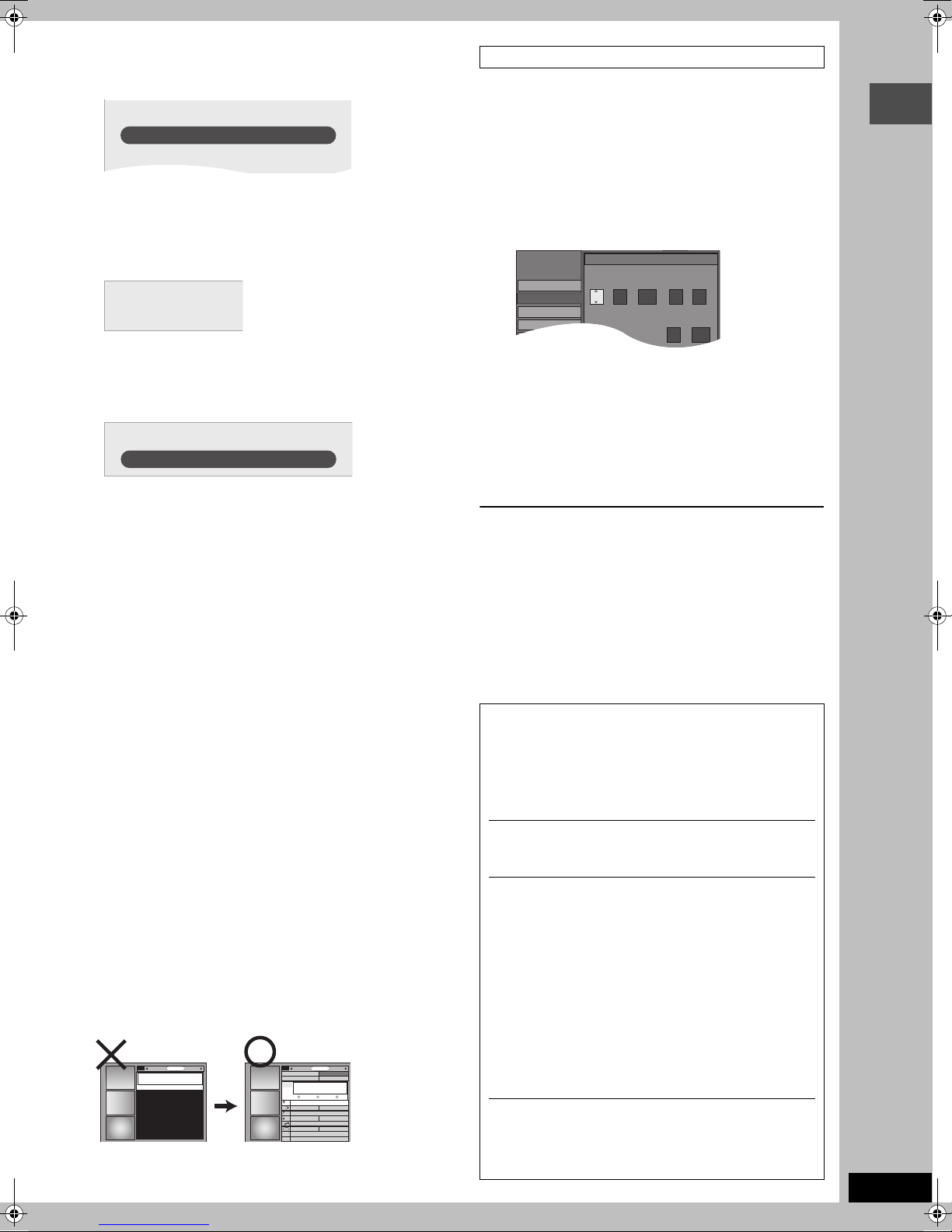
If you find “There is no data for this screen” displayed on the
television when you turn the unit on, the unit has not yet
downloaded the channel line-up.
SORTSCHEDULE LISTINGS
There is no data
for this screen.
This unit may download more than one channel line-up. Follow the
on-screen guidance and select one of these.
TODAY
Last
Channel
87
NWGB
pTV
TV
NWBG
ducation
BOX
ANiMe
Network
PBS
LISTINGS
8:00PM
FAVORITES RECORD INFO.
8:30PM
To use immediately (Manual Clock Setting)
Set the clock manually.
Please note that the program list is not displayed until the unit
downloads it. Timer program recording is only possible manually.
1 Press [SETUP].
2 Press [3, 4] to select “Set Up” and
press [1].
3 Press [3, 4] to select “Manual Clock
Setting” and press [ENTER].
Getting started
4 Press [2, 1] to select the item you
want to change and press [3, 4] to
change the setting.
5 Press [ENTER].
The clock starts.
6 Press [SETUP].
≥DST (Daylight Saving Time): ON or OFF
If you select “ON”, the clock is advanced one hour starting at 2
TM
system
SORTSCHEDULE
a.m. on the first Sunday in April and ending at 2 a.m. on the last
Sunday in October.
≥TIME ZONE shows the time difference from Greenwich
meantime (GMT).
EST (Eastern Standard Time) l GMT j5
CST (Central Standard Time) l GMT j6
MST (Mountain Standard Time) l GMT j7
PST (Pacific Standard Time) l GMT j8
AST (Alaska Standard Time) l GMT j9
HST (Hawaii Standard Time) l GMT j10
In the United States, TV GUIDE and other related marks are
registered marks of Gemstar-TV Guide International, Inc. and/
or one of its affiliates. In Canada, TV GUIDE is a registered
mark of Transcontinental Inc., and is used under license by
Gemstar-TV Guide International, Inc. TV Guide On Screen,
G-LINK, VCR Plusr and PlusCode are registered marks of
Gemstar-TV Guide International and/or one of its affiliates.
The TV Guide On Screen and VCR Plusr systems are
manufactured under license from Gemstar-TV Guide
International, Inc. and/or one of its affiliates.
GEMSTAR-TV GUIDE INTERNATIONAL, INC. AND/
OR ITS RELATED AFFILIATES ARE NOT IN ANY WAY
LIABLE FOR THE ACCURACY OF THE PROGRAM
SCHEDULE INFORMATION PROVIDED BY THE TV
GUIDE ON SCREEN SYSTEM. IN NO EVENT SHALL
GEMSTAR- TV GUIDE INTERNATIONAL, INC. AND/
OR ITS RELATED AFFILIATES BE LIABLE FOR ANY
AMOUNTS REPRESENTING LOSS OF PROFITS,
LOSS OF BUSINESS, OR INDIRECT, SPECIAL, OR
CONSEQUENTIAL DAMAGES IN CONNECTION
WITH THE PROVISION OR USE OF ANY
INFORMATION, EQUIPMENT, OR SERVICES
RELATING TO THE TV GUIDE ON SCREEN SYSTEM.
The TV Guide On Screen and VCR Plusr systems are
protected by one or more issued United States patents such as
6,331,877; 6,239,794; 6,154,203; 5,940,073; 4,908,713;
4,751,578; 4,706,121; 6,466,734; 6,430,359; 6,091,882;
6,049,652; 5,335,079; 5,307,173.
RQT7394
13
STEP
SETUP
Disc
Remote Control Code
Channel
Set Up
Press “±
”
and “ENTER
”
together
for more than 2 seconds on the remote.
3
Set up to match your television and remote control
DVD POWER
TV
POWER
VOLUME
CH
TV/VIDEO
INPUT SELECT
SD/PC
DVD
HDD
Numbered
buttons
Getting started
SETUP
1
456
7809
CANCEL
SKIP
STOP
DIRECT NAVIGATOR
TOP MENU
SUB MENU
PROG/CHECK
DISPLAY
SETUP
Info
DUBBING
23
VCR Plus+
SLOW/SEARCH
PAUSE
PLAY/x1.3
ENTER
TIME SLIP
REC MODEERASE
CHAPTER
PAG E
CH
AUDIO
CM SKIP
FUNCTIONS
RETURN
TV GUIDE
REC
STATUS
TV operation
buttons
3,4,2,1
ENTER
RETURN
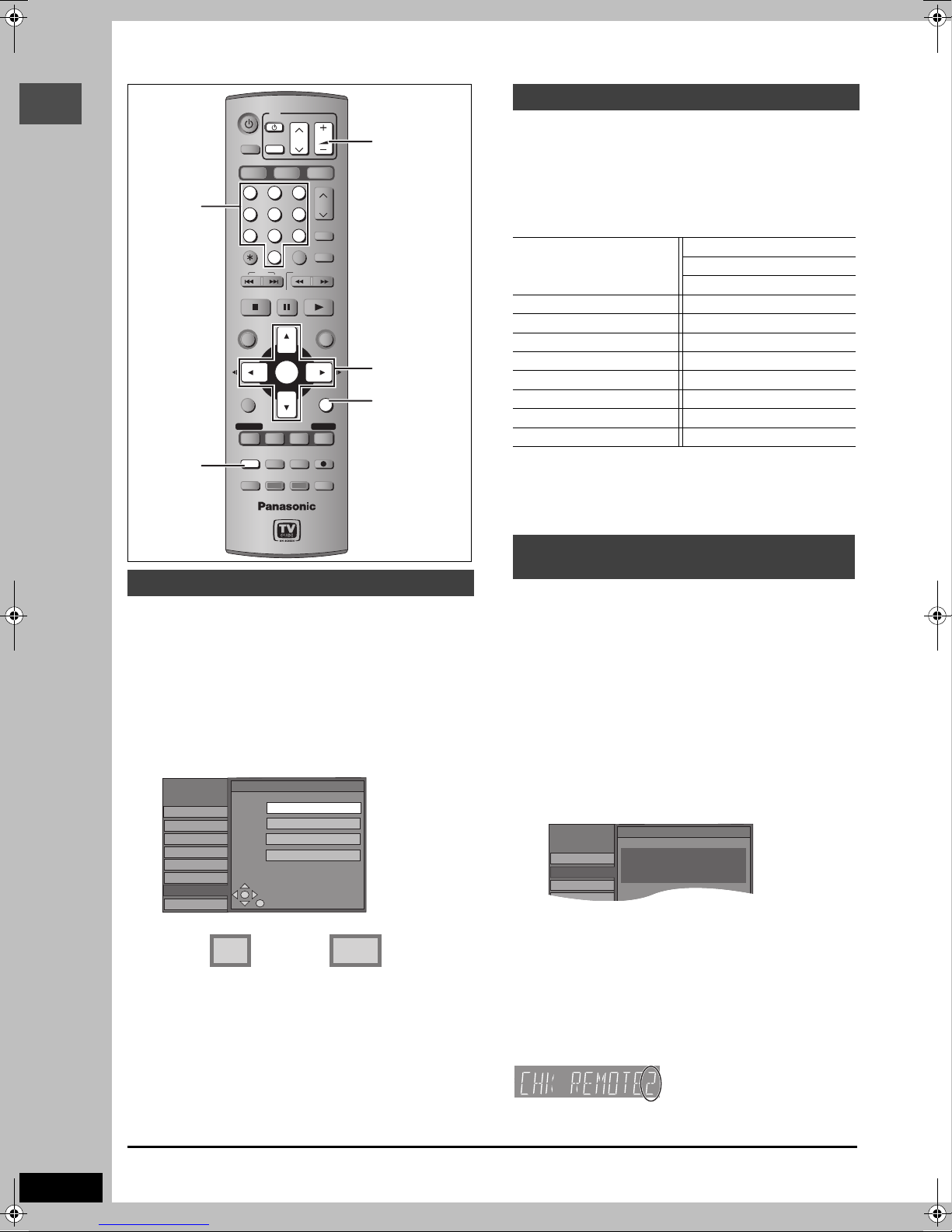
Television operation
You can configure the remote control TV operation buttons to turn
the television on/off, change the television input mode, select the
television channel and change the television volume.
Point the remote control at the television
While pressing [Í POWER TV], enter the
code with the numbered buttons.
e.g., 01: [0] ➡ [1]
Manufacturer and Code No.
Panasonic
National
QUASAR
FISHER 10 SANYO 10
GE 05 SHARP 06, 07
GOLDSTAR 15, 16, 17 SONY 08
HITACHI 12 SYLVANIA 03
JVC 11 THOMSON 05
LG 15, 16, 17 TOSHIBA 09
MAGNAVOX 03 ZENITH 04
MITSUBISHI 13
Test by turning on the television and changing channels. Repeat
the procedure until you find the code that allows correct operation.
≥If your television brand is not listed or if the code listed for your
television does not allow control of your television, this remote
control is not compatible with your television.
01, 02
PHILIPS (RC-5) 03
RCA 05
SAMSUNG 14, 18, 19
When other Panasonic products
respond to this remote control
Selecting television type
You do not have to change the setting when connected to a 4:3
standard aspect television that is not compatible with progressive
output (➡ page 69).
1 Press [SETUP].
2 Press [3, 4] to select “TV Screen”
and press [1].
3 Press [3, 4] to select “TV Type” and
press [ENTER].
SETUP
Channel
Set Up
Disc
Video
Audio
Display
TV Screen
Network
≥Aspect 4:3/Aspect 16:9:
4:3 16:9
TV Type
Aspect 4:3 & 480i
Aspect 4:3 & 480p
Aspect 16:9 & 480i
Aspect 16:9 & 480p
Change the remote control code on the main unit and the remote
control (the two must match) if you place other Panasonic products
close together.
Use “1”, the factory set code, under normal circumstances.
1 Press [SETUP].
2 Press [3, 4] to select “Set Up” and
press [1].
3 Press [3, 4] to select “Remote
Control Code” and press [ENTER].
4 Press [3, 4] to select the code (1, 2,
or 3) and press [ENTER].
5 To change the code on the remote control
While pressing [ENTER], press and
hold the numbered button ([1], [2] or
4:3 standard aspect
television
≥480p/480i:
Select “480p” if the television is compatible with
progressive output.
4 Press [3, 4] to select the item and
press [ENTER].
16:9 widescreen
television
[3]) for more than 2 seconds.
6 Press [ENTER].
∫ When the following indicator appears on the
unit’s display
The unit’s remote control code
To exit the screen
RQT7394
14
Press [SETUP].
Change the code on the remote control to match the main unit’s
(➡ step 5).
To return to the previous screen
Press [RETURN].

STEP
Set as follows when connecting with AUDIO OUT 5.1 ch terminals
(➡ page 9).
SETUP
4
Multi-channel speaker setting
DVD POWER
TV
POWER
VOLUME
CH
TV/VIDEO
INPUT SELECT
SD/PC
DVD
HDD
1
456
7809
CANCEL
SKIP
STOP
DIRECT NAVIGATOR
TOP MENU
SUB MENU
PROG/CHECK
DISPLAY
SETUP
Info
DUBBING
23
VCR Plus+
SLOW/SEARCH
PAUSE
PLAY/x1.3
ENTER
TIME SLIP
REC MODEERASE
CHAPTER
PAG E
CH
AUDIO
CM SKIP
FUNCTIONS
RETURN
TV GUIDE
REC
STATUS
3,4,2,1
ENTER
1 Press [SETUP].
2 Press [3, 4] to select “Audio” and
press [1].
3 Press [3, 4] to select “Speaker” and
press [ENTER].
4 Press [3, 4] to select “Multi
Channel” and press [ENTER].
Front (L) Center Front (R)
a
— Surround —
(LS) (RS)
a c b c a
Settings a, b, and c can be changed as necessary.
To set the speaker presence and size (a)
b a c
Multi Channel Setting
0.0
C
m s
m s
0
0.0
L
Complete
Test
LS
d B
0
d B
0
d Bd B
0
a
R
SW
RS
Subwoofer
c a
5 Press [3, 4, 2, 1] to select the
speaker icon and press [ENTER].
6 Press [3, 4] to select the setting
and press [ENTER].
Icon examples: Surround speaker (LS)
Select when the speaker supports low-frequency
LS
(under 100 Hz) reproduction.
Select when the speaker does not support low-
LS
frequency reproduction.
No sound is output from the speaker.
If the subwoofer is set so that no sound is output, the front
speakers will automatically be set to support low-frequency
reproduction. Connect front speakers that can reproduce the bass
range below 100 Hz if you do not connect a subwoofer.
To set the delay time (b)
(only when the speakers are not placed equidistant from the
seating position)
(Effective only when playing multi-channel discs)
For optimum listening with 5.1-channel sound, all the speakers,
except for the subwoofer, should be the same distance from the
seating position. If you have to place the center or surround
speakers closer to the seating position, adjust the delay time to
make up for the difference.
If distances d (from the center speaker) and f (from the surround
speakers) are the same as or greater than e (from the front
speakers), leave the delay time as “0”, the factory preset.
If either distance d or f is less than e, find the difference in the
relevant table and change to the recommended setting.
L
C
d
e
f
RS
LS
d Center speaker
R
SW
Difference Setting
Approx. 30 cm (1 feet) 1.0 ms
Approx. 60 cm (2 feet) 2.0 ms
Approx. 90 cm (3 feet) 3.0 ms
Approx. 120 cm (4 feet) 4.0 ms
Approx. 150 cm (5 feet) 5.0 ms
f Surround speakers
Difference Setting
Approx. 150 cm (5 feet) 5.0 ms
Approx. 300 cm (10 feet) 10.0 ms
Approx. 450 cm (15 feet) 15.0 ms
7 Press [3, 4, 2, 1] to select “ms”
and press [ENTER].
8 Press [3, 4] to adjust the delay time
and press [ENTER].
To adjust the speaker volume level (c)
9 Press [3, 4, 2, 1] to select “Test”
and press [ENTER].
A test signal is output from one speaker at a time, starting
with the front left speaker and proceeding clockwise.
Front (L)_—)Center_—)Front (R)
:;
Surround (LS)(—————=Surround (RS)
10 While listening to the test signal
Press [3, 4] to adjust the volume of
the center and surround speakers.
≥Adjust the volume of the center and surround speakers so
that they sound the same as the front speaker.
(The front speakers cannot be adjusted here.)
≥No signal is output for the subwoofer. To adjust its volume,
play something, then return to this screen and adjust as
desired.
11 Press [ENTER].
The test signal stops.
Getting started
To finish the speaker setting
Press [3, 4, 2, 1] to select “Complete” and press [ENTER].
RQT7394
15

STEP
Audio
Display
TV Screen
Previous
Now connecting.
It may take a few minutes.
01/01
Next
Network
5
Setting up the Network
5 Press [3, 4] to select “TCP/IP
DVD POWER
TV
POWER
TV/VIDEO
INPUT SELECT
VOLUME
CH
Settings” and press [ENTER].
6 Press [3, 4] to select “Automatic
SD/PC
DVD
HDD
Numbered
buttons
Getting started
¢ CANCEL
: 9
1
456
7809
CANCEL
SKIP
STOP
DIRECT NAVIGATOR
TOP MENU
SUB MENU
SUB MENU
PROG/CHECK
DISPLAY
SETUP
SETUP
Info
DUBBING
23
VCR Plus+
SLOW/SEARCH
PAU SE
PLAY/x1.3
ENTER
TIME SLIP
REC MODEERASE
CHAPTER
PAG E
CH
AUDIO
CM SKIP
FUNCTIONS
RETURN
TV GUIDE
REC
STATUS
3 4 2 1
ENTER
RETURN
(DHCP)” and press [ENTER].
When connecting a computer via a router with its DHCP
disabled
Press [3, 4] to select “Manual” and press [ENTER]
(➡ page 19, To manually enter the DVD recorder’s IP
Address).
SETUP
Channel
Set Up
Disc
Video
Audio
Display
TV Screen
Network
TCP / IP Settings
Automatic (DHCP)
Manual
IP Address
: 192. 168. 0. 14
Subnet Mask
Default Gateway
DNS Server
: 255
: 192
: 192
.
255
.
168. 0. 1
.
168. 0. 1
. 255.
0
≥IP Address : Make a note of this IP address. You will
need it when operating this unit from the
computer.
7 Confirm that a connection has been
established.
This unit’s network setting
Preparation
≥Connect this unit to the Home Network. This can be directly to
another network compatible Panasonic DVD recorder
(➡ page 10).
≥Check the computer’s IP address setting (➡ page 18), if
connecting this unit and a computer when the DHCP on the
router is disabled.
1 Press [SETUP].
2 Press [3, 4] to select “Network” and
press [1].
3 Press [3, 4] to select “Network
Function” and press [ENTER].
4 Press [3, 4] to select “Enable” and
press [ENTER].
SETUP
Channel
Set Up
Disc
Video
Audio
Display
TV Screen
Network
Network Function
Enable
Disable
MAC Address
: 00-08-97-24-01-C4
Unit ID
: 4284 1491 6862 6641
Status
: 0000-0000-20LU-3DDE
3900-0V03-0M52-0L00
Password
: No password
Wait until the display changes (this may take a few minutes).
≥“Now connected to the network.” is displayed if the
connection has been correctly established.
≥“Cannot connect to the network.” is displayed if the
connection has failed. Check the LAN cable connection.
To exit the screen
Press [RETURN] several times.
To return to the previous screen
Press [RETURN].
[Note]
While “Now updating the settings. Please wait for a while.” is
displayed, no operations will be accepted by this unit. Wait about 5
seconds until the highlights appear again.
∫ To change unit names
When more than one network compatible Panasonic DVD recorder
is connected on the Home Network, you need to give each a
unique unit name so that they can be distinguished.
(Factory preset: “DVD Recorder”)
After step 2 (➡ left)
1 Press [3, 4] to select “Unit Name Setting” and press [ENTER].
2 Enter the name (➡ page 46).
RQT7394
16
When more than one network
SETUP
Disc
Video
Channel
Set Up
Registration of Client Unit
Previous
No. Unit Name Model No.
01/01
Next
Add manually
01 Bedroom DMR-E500H
SETUP
Disc
Video
Channel
Set Up
Registration of Client Unit
Previous
No. Unit Name Model No.
01/01
Next
Add manually
01 Bedroom DMR-E500H
compatible Panasonic DVD recorder is
on the Home Network
You can playback video titles on other network compatible
Panasonic DVD recorders on the Home Network.
When more than one network compatible Panasonic DVD recorder
is on the Home Network, the terms “server” and “client” are used.
The “client” is the DVD recorder that you will actually operate to
receive video titles.
The “server” is the DVD recorder that delivers video titles to your
“client”.
Server Client
Router/Hub
Make the following settings so this unit can recognize which DVD
recorder will receive the data. This unit will later function as the
server.
Preparation
≥Connect to the Home Network or another network compatible
Panasonic DVD recorder.
≥Confirm “TCP/IP Settings” is set to “Automatic (DHCP)”
(➡ page 16, step 6).
≥Give all the DVD recorders on the Home Network a unique unit
name. (➡ page 16, To change unit names)
On the unit you want to use as the server
1 Press [SETUP].
2 Press [3, 4] to select “Network” and
press [1].
3 Press [3, 4] to select “Registration
of Client Unit” and press [ENTER].
The unit names of the DVD recorders on the Home Network
will be displayed after a few seconds (up to 15 units).
≥When not displayed (➡ right, “When connected DVD
recorders are not displayed–Renew”)
4 Press [3, 4] to select the DVD
recorder you want to register as a
client and press [ENTER].
“≤” indicates the registered client unit.
≥Press [ENTER] again to cancel.
≥Repeat this step to register other units as clients.
≥You can have up to 4 client units.
To show other pages
Press [3, 4, 2, 1] to select “Previous” or “Next” and press
[ENTER].
≥You can also press [:, 9] to show other pages.
∫ When connected DVD recorders are not
displayed–Renew
In step 3 (➡ left)
1 Press [SUB MENU].
2 Press [3, 4] to select “Renew” and press
[ENTER].
The list will be updated within 15 seconds.
If any DVD recorders are not displayed despite selecting “Renew”,
add them manually (➡ below, Manually adding DVD recorders).
Edit
Delete
Renew
∫ Manually adding DVD recorders
In step 3 (➡ left)
1 Press [3, 4] to select “Add manually” and press [ENTER].
SETUP
Channel
Set Up
Disc
Video
Audio
Display
TV Screen
Network
Add manually
Input MAC address and unit name,
“
Add” button.
then press
MAC Address
Unit Name
✱✱_✱✱_✱✱_✱✱_✱✱_✱✱
Unit
Add
“Add manually”
screen
2 Press [3, 4] to select “MAC Address” and press [ENTER].
3 Press [3, 4, 2, 1] to enter the MAC Address of the unit you
want to use as the client and press [ENTER].
≥To check the MAC Address (➡ page 16, step 4).
4 Press [3, 4] to select “Unit Name” and press [ENTER].
5 Enter the name (➡ page 46).
6 Press [3, 4] to select “Add” and press [ENTER].
≥You can manually add up to 4 units.
≥“Model” is displayed in the “Model No.” column.
≥You cannot check the properties of manually added DVD
recorders.
∫ To check the properties of the DVD recorders
on the list
(You cannot do this with manually added DVD recorders.)
In step 3 (➡ left)
1 Press [3, 4] to select the DVD recorder and
press [SUB MENU].
Properties
Delete
Renew
2 Press [3, 4] to select “Properties” and press
[ENTER].
The model name, manufacturer and MAC address of the DVD
recorder will be displayed.
∫ To delete DVD recorders from the list
In step 3 (➡ left)
1 Press [3, 4] to select the DVD recorder and press
[SUB MENU].
2 Press [3, 4] to select “Delete” and press [ENTER].
3 Press [2, 1] to select “Delete” and press [ENTER].
∫ To correct the setting of manually added DVD
recorders
In step 3 (➡ left)
1 Press [3, 4] to select the manually added DVD recorder and
press [SUB MENU].
2 Press [3, 4] to select “Edit” and press [ENTER].
3 Press [3, 4] to select the item and make the correction.
4 Press [3, 4] to select “Set” and press [ENTER].
To exit the screen
Press [RETURN] several times.
To return to the previous screen
Press [RETURN].
Getting started
RQT7394
17

STEP
5Setting up the Network
Refer to the control reference on page 16.
To be able to operate this unit from a
computer on the Home Network
To check the computer’s IP address
On the computer
1 Click [start] ➡ [Control Panel].
Double-click [Network Connections].
When connecting a computer via a router with its
DHCP enabled
Confirm “TCP/IP Settings” is set to “Automatic (DHCP)”
(➡ page 16, step 6).
Getting started
The settings on page 18–19 are not required.
When connecting a computer via a router with its
DHCP disabled
Please confirm the following were carried out correctly.
1 Check the computer’s IP address (➡ right, step 4).
2 Enter the DVD recorder’s IP address manually (➡ page 19).
2 Right-click the [Local Area
Connection]§ icon and click
[Properties].
§
A message may appear below the icon such as [Bridge
Connections] or [Network Bridge].
3 Select [Internet Protocol (TCP/IP)]
and click [Properties].
4 Check the IP address setting.
RQT7394
18
Please make a note of the “IP address”, “Subnet mask”,
“Default gateway” and “Preferred DNS server” settings
(These will be needed during DVD recorder setting).
5 Click [Cancel].
You will exit the “Internet Protocol (TCP/IP) Properties”
window.
6 Click [Cancel].
You will exit the “Local Area Connection Properties” window.
≥Screen shots reprinted by permission from Microsoft Corporation.

To manually enter the DVD recorder’s IP Address
On the DVD recorder
After step 5 (➡ page 16)
1 Press [3, 4] to select “Manual” and
press [ENTER].
SETUP
Channel
Set Up
Disc
Video
Audio
Display
TV Screen
Network
TCP / IP Settings
IP Address
Subnet Mask
Default Gateway
DNS Server
Press “Set” to store the values after input.
,,,.,,,.,,,.,,,
,,,.,,,.,,,.,,,
,,,.,,,.,,,.,,,
,,,.,,,.,,,.,,,
Set
2 Press [3, 4] to select “IP Address”
and press [ENTER].
3 Press the numbered buttons to enter
the number and press [ENTER].
≥Press [2, 1] to move the cursor.
≥Press [¢ CANCEL] to clear the numbers.
Repeat step 2 and 3 to enter “Subnet Mask”, “Default
Gateway” and “DNS Server” numbers.
IP Address
If the computer’s IP address is 192.168.0.15, enter
192.168.0. and then enter an arbitrary number, except 15,
between 2 and 254 (➡ page 18, step 4).
Subnet Mask
Enter the same set of digits as the computer’s Subnet mask
(➡ page 18, step 4).
Default Gateway
Enter the same set of digits as the computer’s Default
gateway (➡ page 18, step 4).
DNS Server
Enter the same set of digits as the computer’s Preferred
DNS server (➡ page 18, step 4).
Getting started
Example:
IP Address§ :
Subnet Mask : 255.255.255.0
Default Gateway : 192.168.0.1
DNS Server : 192.168.0.1
§
Make a note of this IP address. You will need it when
operating this unit from the computer (➡ page 56).
192.168.0.14
4 Press [3, 4] to select “Set” and
press [ENTER].
≥Once the connection has been correctly established “Now
connected to the Local Area Network” will be displayed.
To exit the screen
Press [RETURN] several times.
To return to the previous screen
Press [RETURN].
RQT7394
19

HDD, disc and card information
HDD and discs you can use for recording and play
Data that
Type Logo
Hard disk drive
(HDD)
≥400 GB
Getting started
Indicated in
these
instructions with
–
[HDD]
DVD-RAM
≥4.7 GB/9.4 GB,
12 cm (5z)
≥2.8 GB, 8 cm
(3z)
[RAM]
DVD-R
≥4.7 GB, 12 cm
(5z)
≥1.4 GB, 8 cm
(3z)
[DVD-R]
§
conventionally recorded programs
≥
We recommend using Panasonic discs and cards. DVD-R from other manufacturers may not be recorded or played due to the condition of the recording.
∫ Which should I use, DVD-RAM or DVD-R?
The following chart indicates the differences. Select based upon what you require.
(±:Possible, t:Impossible) DVD-RAM DVD-R
Re-writable ±t
Edit ±§1
Play on other players
Recording both Main and SAP of
MTS broadcast
Recording broadcasts that allow
one copy
Recording 16:9 aspect picture ±§6
can be
recorded
and played
§
Video
Still pictures
MPEG4
§
Video
Still pictures
MPEG4
§
Video
Instructions
Temporary storage
≥You can record up to 709 hours [in EP (8H) mode] (➡ page 23, Recording modes and
approximate recording times).
≥
You can view the title being recorded from the beginning (Chasing playback, Time Slip) (➡page 24).
≥You can record digital broadcasts that allow “One time only recording”. You can transfer (dub) a
recorded title to a CPRM compatible DVD-RAM; however, the title is erased from the HDD
(➡ page 68).
≥
You can play and transfer (dub) still pictures taken on a digital camera etc. (➡page 34, 52).
≥You can play and transfer (dub) MPEG4 motion pictures taken on a SD Video Camera etc.
(➡ page 36, 54)
≥You can record MPEG4 data at the same time as recording a TV program. (➡ page 22)
Re-writable discs for backup use
≥You can record approximately up to 8 hours on a single-sided disc and 16 hours on a double-
sided disc (➡
≥You can view the title being recorded from the beginning (Chasing playback, Time Slip)
(➡ page 24).
≥Scratch and dust resistant cartridge discs and large capacity double sided discs (9.4GB) are
commercially available.
≥You can record digital broadcasts that allow “One time only recording” when using CPRM
(Content Protection for Recordable Media) compatible discs (➡ page 68). You cannot transfer
(dub) a recorded title.
≥This unit is compatible with 1k–5k recording speed discs.
≥You can transfer (dub) up to 40k recording speed by using a high speed recording compatible
disc (➡ page 47).
≥
You can play and transfer (dub) still pictures taken on a digital camera etc. (➡page 34, 52)
≥You can play and transfer (dub) MPEG4 motion pictures taken on a SD Video Camera etc.
(➡ page 36, 54)
page 23, Recording modes and approximate recording times
).
One time recording discs for backup use (recordable until the disc is full)
≥You can record up to 8 hours [in EP (8H) mode] (➡ page 23, Recording modes and
approximate recording times).
≥
By finalizing the disc, you can play it in a DVD player as DVD-Video (Play only) (➡page 60, 68).
≥You cannot record digital broadcasts that allow “One time only recording”.
≥This unit is compatible with 1k–8k recording speed discs.
≥You can transfer (dub) up to 64k recording speed by using a high speed recording compatible
disc (➡ page 47).
§1
You can erase, enter name and change thumbnail. Available
space does not increase after erasing.
§2
Only on DVD-RAM compatible players.
§3
After finalizing the disc (➡page 60
§2
±
±
§5
±
§3
±
§4
t
t
§4
Only one is recorded (➡ page 63, Select MTS).
§5
CPRM (➡ page 68) compatible discs only.
§6
The picture is recorded in 4:3 aspect.
[Note]
When “DVD-R High-Speed Recording” is set to “On” the restrictions
on secondary audio recording, etc. are also applied to DVD-RAM.
Turn this setting “Off” if high speed transfer (dubbing) to DVD-R is
not necessary when recording a program (➡ page 62).
, 68
).
Play-only discs [12 cm (5z)/8 cm (3z)]
Disc type Logo Instructions
RQT7394
DVD-Audio
[DVD-A]
DVD-Video
[DVD-V]
Video CD
[VCD]
Audio CD
[CD]
High fidelity music discs
High quality movie and music
discs
Recorded music and video (including
CD-R/RW)
Recorded audio and music (including
CD-R/RW)
CD-R and CD-RW with music
recorded in MP3 (➡ page 33)
20
≥
This unit plays CD-R/CD-RW discs (audio recording discs) which have
been recorded under one of the following standards: CD-DA, MP3 and
Video CD. Close the session or finalize the disc after recording.
Play may be impossible on some CD-R or CD-RW discs due to the
condition of the recording.
≥The producer of the disc can control how discs are played. So you
may not always be able to control play as described in these
operating instructions. Read the disc’s instructions carefully.
Regarding DVD-Audio
Some multi-channel DVD-Audio will prevent down-mixing (➡page 68)
of all or part of their contents if this is the manufacturer’s intention.
When playing such discs, or such parts of the disc, unless the number
of connected speakers is the same as the disc’s channel
specification, audio will not be output properly (e.g. part of the audio is
missing, multi-channel audio cannot be selected and audio is played
in two channels). Refer to the disc’s jacket for more information.
Discs that cannot be played
≥2.6 and 5.2 GB DVD-RAM, 12 cm (5z)
≥3.95 and 4.7 GB DVD-R for Authoring
≥
Unfinalized DVD-R recorded on other equipment (➡page 68, Finalize)
≥PAL discs (you can still play the audio on DVD-Audio)
≥DVD-Video with a region number other than “1” or “ALL”
≥DVD -ROM, DVD -RW, iR, iRW, CD-ROM, CDV, CD-G, Photo CD,
CVD, SVCD, SACD, MV-Disc, PD, Divx Video Disc, etc.
Note about using a DualDisc
The digital audio content side of a DualDisc does not meet the
technical specifications of the Compact Disc Digital Audio
(CD-DA) format so play may not be possible.

Cards useable on this unit
Type
be recorded
Instructions
and played
Data that can
SD Memory Card
MultiMediaCard
SD Memory Card
MultiMediaCard
CompactFlash
SmartMedia
EMORYSTICK
M
xD-Picture Card
Microdrive
ATA Flash PC
Card
Mobile hard disk
You can insert
§1
directly into the SD
card slot.
[SD]
You can insert into
the PC card slot
using an adaptor
(TYPE II PC card
adaptor).
[PC]
You can insert
directly into the PC
card slot.
§2
[PC]
Still pictures
MPEG4 (With
SD Memory
Card,
MultiMediaCard
Mobile hard
disk)
≥You can play and transfer (dub) still pictures taken on a digital camera etc.
(➡ page 34, 52).
≥You can set the DPOF (Digital Print Order Format) for automatic printing on
your home printer or at a photo developing store (➡ page 44, 68).
With SD Memory Card, MultiMediaCard, Mobile hard disk
≥You can play and transfer (dub) MPEG4 motion pictures taken on a SD Video
Camera etc. (➡ page 36, 54)
≥You can transfer (dub) MPEG2 motion pictures taken on a SD Video Camera
etc. to the HDD or DVD-RAM. (These will be treated as video titles in the HDD
or DVD-RAM.) (➡ page 54)
With SD Memory Card and MultiMediaCard
≥You can transfer (dub) at high speed MPEG4 titles being simultaneously
recorded to the HDD (➡ page 54).
≥You can also transfer (dub) video titles already recorded on the HDD or DVD-
,
RAM to a card by converting to MPEG4 format (➡ page 54).
≥Compatible with: FAT 12 or FAT 16
≥We recommend using a Panasonic SD card.
≥You cannot use SD cards that exceed 2 GB.
≥
We recommend using this unit to format a card before recording (➡page 59, 68).
≥You may not be able to use the card if formatted on a computer.
§1
Includes miniSDTM Cards. A miniSDTM adaptor needs to be inserted before
using these cards.
§2
Content saved on SD media storage (SV-PT1).
You can only play the saved still pictures or MPEG4 titles, and transfer (dub)
the data onto other cards, HDD or DVD-RAM.
Suitable SD Memory Cards
≥You can use SD Memory Cards with the following capacities (from 8 MB to 1 GB).
8 MB, 16 MB, 32 MB, 64 MB, 128 MB, 256 MB, 512 MB, 1 GB (Maximum)
Please confirm the latest information on the following website.
http://panasonic.co.jp/pavc/global/cs
(This site is in English only.)
≥If the SD Memory Card is formatted on other equipment, the time spent for recording may become longer. Also if the SD Memory Card is
formatted on a PC, you may not be able to use it on this unit. In these cases, format the card on this unit (
≥This unit supports SD Memory Cards formatted in FAT 12 system and FAT 16 system based on SD Memory Card Specifications.
≥We recommend using a Panasonic SD card.
➡
page 59
, 68
).
Getting started
Structure of folders displayed by this unit
The following can be displayed on this unit.
¢¢¢: Numbers XXX: Letters
Card
(Higher folder)
DCIM
¢¢¢XXXXX
IM¢¢CDPF or IMEXPORT
XXXX
XXXX
SD_VIDEO
PRL
PRG
MGRINFO
§
Folders can be created on other equipment. However, these folders cannot be selected as a transferring (dubbing) destination.
(Picture folder)
XXXX
¢¢¢¢
.JPG
¢¢¢¢
.TIF
§
.JPG
.TIF
(MPEG4 folder)
¢¢¢
.ASF
(MPEG2 folder)
¢¢¢
.MOD
¢¢¢
.MOI
¢¢¢
.PGI
(MPEG2 information manager folder)
¢¢¢¢
¢¢¢¢
¢¢¢
MOL
¢¢¢
MOV
MOV
PRG
XXXX
≥The folder cannot be displayed if the numbers are all “0” (e.g., DCIM000 etc).
≥If a folder name or filename has been input using other equipment, the name may not be displayed properly or you may not be able to play or
edit the data.
DVD-RAM
JPEG
DCIM
SD_VIDEO
DCIM¢¢¢
¢¢¢XXXXX
¢¢¢XXXXX
XXXX
XXXX
PRL
¢¢¢
MOL
(Higher folder)
XXXX
¢¢¢¢
XXXX
¢¢¢¢
¢¢¢¢
¢¢¢¢
(MPEG4 folder)
¢¢¢
.ASF
(Picture folder)
.JPG
.TIF
§
.JPG
.TIF
RQT7394
21

Recording television programs
HDD
SP
CH
HDD
XP
CH
HDD, DVD indicator
POWER
POWERPOWERPOWERPOWER
SD CARD
EJECT
PC CARD
HDD
Time Slip indicator
TIME SLIP
DVD POWER
TV
Recording
Numbered
buttons
;
∫
DIRECT
NAVIGATOR
POWER
TV/VIDEO
INPUT SELECT
DVD
HDD
23
1
456
7809
CANCEL
SKIP
STOP
PAU SE
DIRECT NAVIGATOR
TOP MENU
ENTER
SUB MENU
PROG/CHECK
DISPLAY
SETUP
Info
DUBBING
CH
SD/PC
VCR Plus+
CM SKIP
SLOW/SEARCH
PLAY/x1.3
FUNCTIONS
TV GUIDE
TIME SLIP
REC MODEERASE
CHAPTER
VOLUME
PAG E
CH
AUDIO
RETURN
REC
STATUS
[HDD] [RAM] [DVD-R]
≥It is not possible to record to both HDD (Hard Disk Drive) and DVD
drive simultaneously.
≥You can record up to 500 titles on HDD, 99 titles on one disc.
≥It is not possible to record continuously from one side of a double
sided disc to the other. You will need to eject the disc and turn it
over.
hen using 8 cm (3″) DVD-RAM, remove the disc from the cartridge.
≥W
≥It is not possible to record digital broadcasts that allow “One time
only recording” onto DVD-R or 2.8 GB DVD-RAM discs.
≥It is not possible to record directly onto a card. To set the
simultaneous MPEG4 recording function ➡ right
When transferring (dubbing) in high speed mode to DVD-R
after you have recorded to the HDD.
Set “DVD-R High-Speed Recording” to “On” before recording to
the HDD (➡ page 62).
However, the following restrictions apply.
≥Even 16:9 aspect (Widescreen) programs are recorded in 4:3
aspect.
≥Even if “Hybrid VBR Resolution” is set to “Automatic”, it
changes to “Fixed” automatically (➡ page 62).
When recording to DVD-R
≥When recording MTS broadcasts
–If you do not connect a cable TV box
Select “Main” or “SAP” in “Select MTS” in the SETUP menu
(➡ page 63).
–If you connect a cable TV box
Select “Main” or “SAP” on the cable TV box.
≥In order to play a DVD-R recorded using this unit on
another playback source, the disc must first be finalized
RQT7394
22
(➡ page 60).
2
OPEN/CLOSE
TIME SLIP
DVD
1
DRIVE SELECT
HDD DVD SD PC
REC
TIME SLIP
CH
3
1
3
AUDIO
1
FUNCTIONS
3 4 2 1
ENTER
RETURN
TIME SLIP
4
5
STATUS
∫ Simultaneous MPEG4 recording [HDD]
If you set “MPEG4 Recording Mode” “XF”, “SF”, “F”, “N” or “E”
∫
1
before recording to the HDD, programs that are recorded as
video titles will be simultaneously recorded in MPEG4 format.
You can transfer (dub) these MPEG4 titles to a SD Memory Card
/x
1.3
or MultiMediaCard quickly (➡ page 54).
Digital broadcasts that allow “One time only recording”
cannot be recorded as a MPEG4 title.
Prior to recording to the HDD
5
1 Set the picture quality of the MPEG4 data to be recorded
in “MPEG4 Recording Mode” in the SETUP menu
(➡ page 62).
2 Set the capacity of the card you are using in “SD Card
Capacity” in the SETUP menu (➡ page 62).
≥When recording MTS broadcasts
–If you do not connect a cable TV box
Select “Main” or “SAP” in “Select MTS” in the SETUP menu
(➡ page 63)
–If you connect a cable TV box
Select “Main” or “SAP” on the cable TV box.
[Note]
≥The audio for MPEG4 is monaural and the aspect ratio of the
recorded picture is 4:3.
≥You cannot use the simultaneous MPEG4 recording function
while transferring (dubbing) or “DV automatic recording”.
≥When recording a program without recording limits after
recording programs with recording limits, the first 10 seconds or
so of the MPEG4 title may not be recorded.
Preparation
Press [RETURN] to exit the television program list if it is displayed on
the television. To turn off auto start up of the television program list
➡ page 29, “Review options” menu
1 Press [HDD] or [DVD] to select the
recording drive.
The HDD or DVD indicator lights up on the unit.
2 If you selected the DVD drive
Press [< OPEN/CLOSE] on the main
unit to open the tray and insert a disc.
≥Press the button again to close the tray.
Insert label-up.
Insert with the arrow facing in.
Insert fully so it
clicks into place.
3 Press [WXCH] to select the channel.
To select with the numbered buttons:
TV Mode (Airwaves)
e.g., 5: [0] ➡ [5]
15: [1] ➡ [5]
CATV Mode (Cable)
e.g., 5: [0] ➡ [0] ➡ [5]
15: [0] ➡ [1] ➡ [5]
115: [1] ➡ [1] ➡ [5]
≥Select the audio to record (➡ page 23).
4 Press [REC MODE] to select the
recording mode (XP, SP, LP, or EP).
Remaining time on the disc
≥To record sound using LPCM (XP mode only):
Set “Audio for XP Recording” to “LPCM” in the SETUP menu
(➡ page 63).
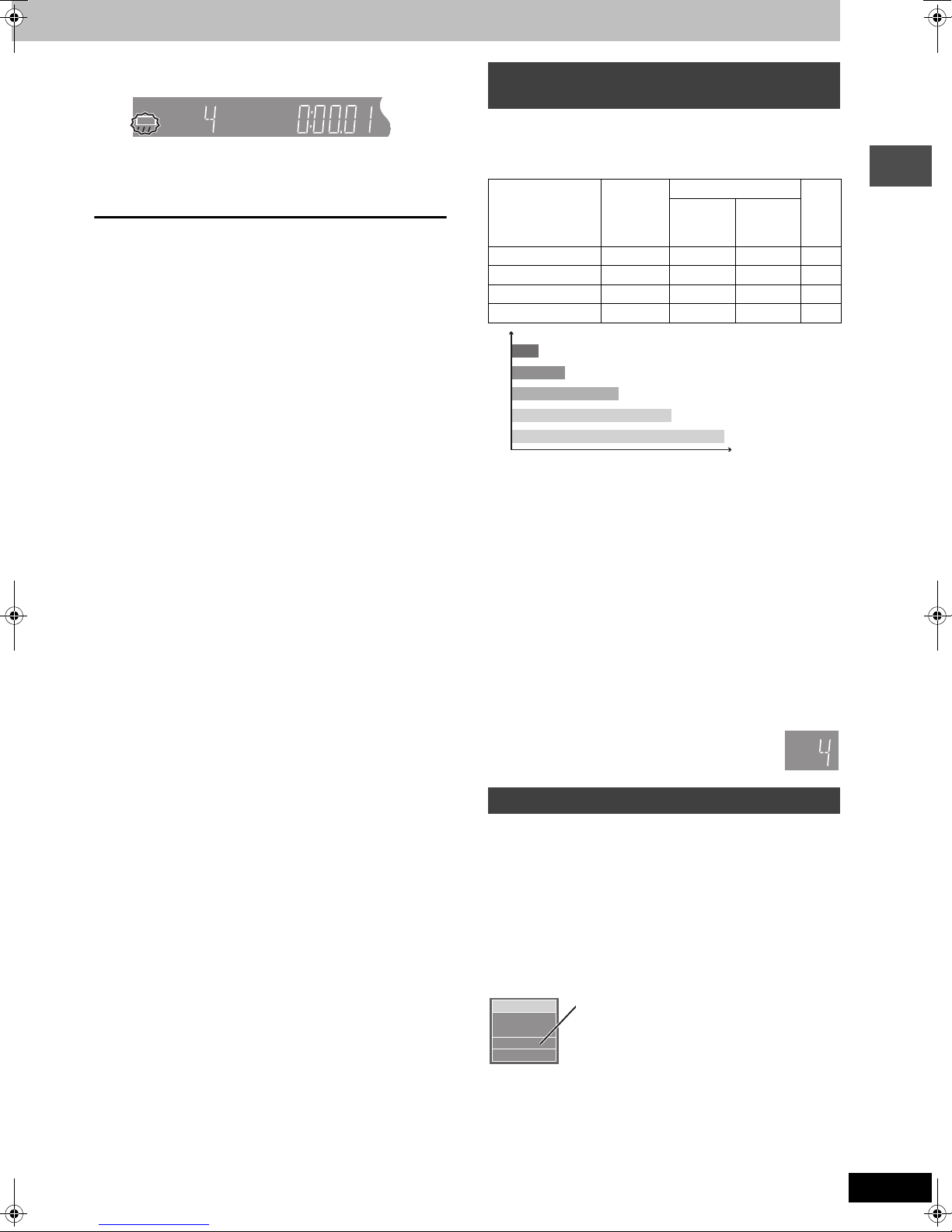
5 Press [¥ REC] to start recording.
HDD
XP
CH
REC
Recording will take place on open space on the HDD or on
disc. Data will not be overwritten.
≥You cannot change the channel or recording mode during
recording.
≥You can record while the unit is on standby for timer recording, but
once the time for the timer recording to begin is reached, any
recording taking place will stop and the timer recording will begin.
∫ To pause recording
Press [;].
Press again to restart recording.
(Title is not split into separate titles.)
∫ To stop recording
Press [∫].
From the start to the end of the recording is called one title.
[HDD]
When continuously recording for long durations, titles are
automatically divided every 8 hours.
[DVD-R]
It takes about 30 seconds for the unit to complete recording
management information after recording finishes.
∫ To specify a time to stop recording—One Touch
Recording
During recording
Press [¥ REC] to select the recording time.
Each time you press the button:
0:30 "# 1:00 "# 1:30 "# 2:00 "# 3:00 "# 4:00
^"""""""""""" Counter (cancel) ,"""""""""""}
≥This does not work during timer recordings (➡ page 25) or while
using Flexible Recording (➡ page 24).
To stop recording partway
Press [∫].
Off Timer
The unit switches to standby after about 6 hours in the stop mode.
You can turn this feature off or change the time to 2 hours
(➡ page 61, “Off Timer”).
Recording modes and approximate
recording times
Depending on the content being recorded, the recording times may
become shorter than indicated.
If you set simultaneous MPEG4 recording (➡ page 22), the available
recording time to HDD is reduced.
HDD
Mode Single-
XP (High quality) 89 1 2 1
SP (Normal) 177 2 4 2
LP (Long play) 355 4 8 4
EP (Extra long play)
XP
SP
LP
§
EP (6H)
Picture quality
EP (8H)
§
When “Recording Time in EP Mode” is set to “EP (6H)” in the
SETUP menu.
The sound quality is better when using “EP (6H)” than when using
“EP (8H)”.
(400 GB)
709 (532
Recording time
§
)8 (6§) 16 (12§)8 (6§)
DVD-RAM DVD-
sided
(4.7 GB)
[Note]
When recording to DVD-RAM using EP (8H) mode, play may not be
possible on DVD players that are compatible with DVD-RAM. In this
case use EP (6H) mode.
FR (Flexible Recording Mode)
The unit automatically selects a recording rate between XP and EP
(8H) that will enable the recordings to fit in the remaining disc space
with the best possible recording quality.
≥You can set when transferring (dubbing) or programming timer
recordings.
≥
When recording to the HDD, picture quality is automatically adjusted
to precisely fit a transferred (dubbed) title on a 4.7 GB disc.
≥All the recording modes from XP to EP appear in the
display.
Double-
sided
(9.4 GB)
(Unit: hour)
R
(4.7
GB)
XP
SP
LP
CH
EP
Recording
Selecting audio to record
[HDD] [RAM]
Press [AUDIO].
[.
Stereo: Main audio (stereo)
l
l
l
SAP: Secondary audio program (SAP)
l
l
a-
Mono: Main audio (monaural)
HDD
CH 12
((
Stereo
≥If you change the sound setting while recording, the recorded
sound will also change.
[DVD-R]
[HDD] [RAM] (When recording sound in LPCM)
[HDD] [RAM] (When “DVD-R High-Speed Recording” is set to “On”)
≥If the broadcast is “MonoiSAP”, audio will be
v
monaural even if you select Stereo mode.
≥If recorded in SAP mode, main audio is also
v
recorded.
≥Select “Mono” if reception is poor during a stereo
broadcast.
e.g., “Stereo” is selected
“((” appears when the unit is receiving the audio
type you selected.
Select the audio (Main or SAP) in “Select
MTS” in the SETUP menu (➡ page 63).
RQT7394
23
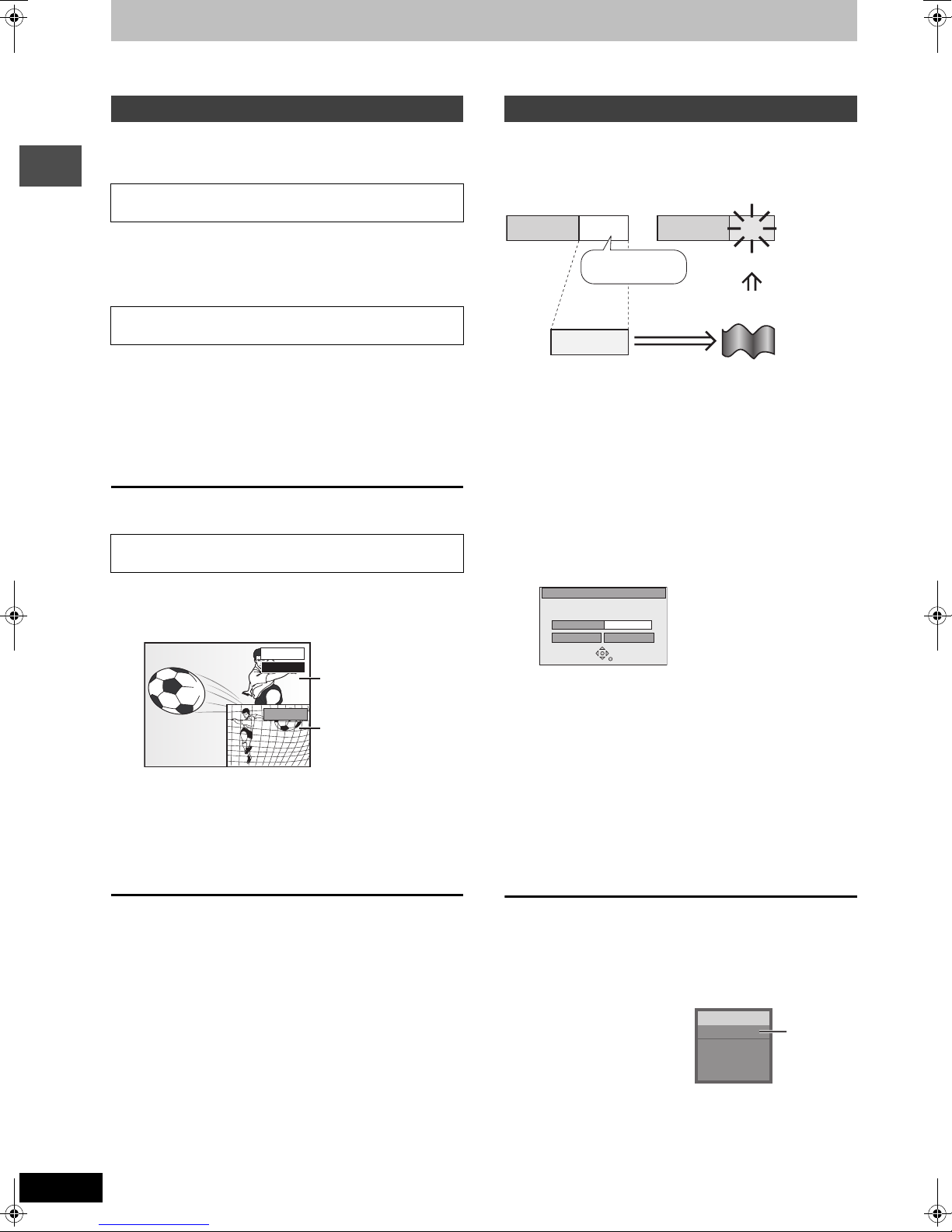
Recording television programs
Refer to the control reference on page 22.
[HDD] [RAM]
Playing while you are recording
You can change the drive and play while recording on this unit. Also,
while recording to the HDD or to DVD-RAM you can view the title
being recorded from the beginning as well as play a recorded title.
Playing from the beginning of the title you are
recording—Chasing playback
Press [1](PLAY).
Time Slip indicator on the main unit lights.
Recording
Playing a title previously recorded while recording—
Simultaneous rec and play
1 Press [DIRECT NAVIGATOR].
2 Press [3, 4, 2, 1] to select a title
and press [ENTER].
Time Slip indicator on the main unit lights.
To exit the Direct Navigator screen
Press [DIRECT NAVIGATOR].
Reviewing the recorded images while recording—
Time Slip
1 Press [TIME SLIP].
Time Slip indicator on the main unit lights.
PLAY
0 min
REC
≥You will hear the playback audio.
Play starts from 30
seconds previous.
The image currently being
recorded
2 Press [3, 4] to select the time and
press [ENTER].
≥Press [TIME SLIP] to show the play images in full. Press
again to show the play and recording images.
[HDD] [RAM] [DVD-R]
Flexible Recording
The unit sets the best possible picture quality that fits the recording
within the remaining disc space. The recording mode becomes FR
mode.
e.g.,
Recorded
Program to be recorded
Preparation
≥Select the channel to record.
≥Press [HDD] or [DVD] to select the recording drive.
Remain
45 minutes in
SP mode
60 minutes
Perfectly fit!
Recording rate
between SP and LP
1 While stopped
Press [FUNCTIONS].
2 Press [3, 4, 2, 1] to select
“FLEXIBLE RECORDING” and press
[ENTER].
FLEXIBLE REC
Record in FR mode
Maximum rec time
Set recording time
3 Hour 00 Min.
3 Hour 00 Min.
Start Cancel
3 Press [2, 1] to select “Hour” and
“Min.” and press [3, 4] to set the
recording time.
≥You can also set the recording time with the numbered
buttons.
≥You cannot record more than 8 hours.
4 When you want to start recording
Press [3, 4, 2, 1] to select “Start”
and press [ENTER].
Recording starts.
∫ To stop play
Press [∫].
∫ To stop recording
2 seconds after play stops
Press [∫].
∫ To stop timer recording
Press [∫], then [ENTER] within 5 seconds.
≥You can also press and hold [∫] on the main unit for more than 3
seconds to stop recording.
RQT7394
24
To exit the screen without recording
Press [RETURN].
To stop recording partway
Press [∫].
To show the remaining time
Press [STATUS].
HDD
REC 0:59
CH71
Stereo
Remaining
time

Timer recording
TODAYTODAY
Last
Channel
SORTSCHEDULE
FAVORITES RECORD INFO.
87
NWGB
p
T
V
TV
NWBG
ducation
LISTINGS
8:30PM8:00PM
8:00 8:30
DVD POWER
Í
Numbered
buttons
∫
DVD POWER
TV
POWER
TV/VIDEO
INPUT SELECT
DVD
HDD
23
1
456
7809
CANCEL
SKIP
STOP
DIRECT NAVIGATOR
CH
VCR Plus+
SLOW/SEARCH
PAU SE
VOLUME
SD/PC
PAG E
CH
AUDIO
CM SKIP
PLAY/x1.3
FUNCTIONS
PAG E X CH W
VCR Plusr
≥As long as the setting is not changed, the program is
recorded to the HDD in the recording mode selected by the
unit. To change the setting ➡ below.
∫ To change the setting
1Press [SUB MENU] to go to the Navigation
menu.
2Press [2, 1] to select “SCHEDULE”.
3Press [3, 4] to select the program and press
[ENTER].
Start early by :
End late by :
Destination :
Quality :
00 minutes
00 minutes
SP
HDD
Recording
TOP MENU
SUB MENU
ENTER
RETURN
3 4 2 1
ENTER
SUB MENU
PROG/CHECK
DUBBING
Info
PROG/CHECK
SETUP
Info
DUBBING
DISPLAY
TIME SLIP
REC MODEERASE
CHAPTER
TV GUIDE
REC
STATUS
TV GUIDE
CHAPTER
[HDD] [RAM] [DVD-R]
Using the TV Guide On ScreenTM
system to make timer recordings
You can perform timer recording easily by just marking the desired
program(s) in a television program list.
≥You can enter up to 8 days in advance.
≥The program name becomes the recorded title if the program is
listed on the television program list.
1 Press [TV GUIDE].
Navigation menu
4Change the setting as necessary and press
[ENTER].
≥To set recording to start early or end late
Press [3, 4] to select “Start early by” or “End late by” and
press the numbered buttons to enter minutes (up to 99).
≥To change the recording mode
Press [3, 4] to select “Quality” and press [DUBBING]
(Blue).
Each time you press the button:
LP # EP # FR # XP # SP
^==============}
≥To change the recording drive
Press [3, 4] to select “Destination” and press [DUBBING]
(Blue).
Each time you press the button:
HDD ,-. DVD
When the recording drive is “DVD” and there is not enough
remaining space, recording automatically switches to the
“HDD” (➡ page 27, Relief Recording).
4 Press [TV GUIDE].
Returns to the television screen.
≥The unit is not off. To save power, turn the unit off by
pressing [Í DVD POWER ].
≥When using the cable TV box, make sure the cable TV box is
turned on.
2 Press [3, 4, 2, 1] to select the
program.
≥To skip one screen
Press [PAGE X CH W].
≥To skip 24 hours in the list
Press [3, 4, 2, 1] to select “LISTINGS” and:
Press [CHAPTER] (Green) (forward).
Press [DUBBING] (Blue) (backward).
3 Press [CHAPTER] (Green).
R
“ ” appears in the list to indicate that the program is set for
timer recording.
≥Press [CHAPTER] (Green) to cancel.
≥Press [DUBBING] (Blue) to change recording frequency.
Each time you press the button:
[.
l
l
l
l
l
l
{
Repeat steps 2–3 to program other recordings.
Records only once.
R
;
Records when the broadcast time and program
R
R
name match.
;
Records weekly.
R
W
;
Temporarily cancels the program timer
R
recording without deleting the program setting.
To check, change or delete the program ➡ page 27
To utilize TV Guide On Screen
TM
system, see also page 28.
Notes on timer recording ➡ page 27
∫ To cancel recording when recording has already
begun
Press [∫], then [ENTER] within 5 seconds.
≥You can also press and hold [∫] on the main unit for more than 3
seconds to stop recording.
≥There may be some channels that are not displayed in the
television program list even if they are receivable. In this case set
them manually (➡ page 26).
RQT7394
25
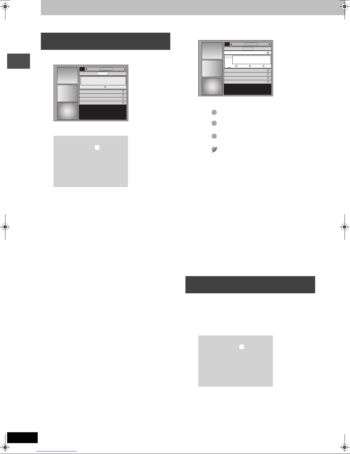
Timer recording
Refer to the control reference on page 25.
Manually programming timer
recordings
1 Press [PROG/CHECK].
Recording
FAVORITES
Sat 2:00pm Dodzilla Once
Sat 3:00pm Bull house Weekly
Sat 3:30pm Be switched Weekly
Sat 4:00pm Baseball Once
RECORD
2 Press [CHAPTER] (Green).
Date :
Start Time :
End Time :
Channel :
Quality :
Destination :
PlusCode :
4 / 1 / 04
8 : 00 pm
10 : 00 pm
56
SP
HDD
=========
SET TIMER
4 Press [ENTER].
FAVORITES
Sat 1:00pm NWBG Once
87
NWBG
SP
HDD
REMOVE
LISTINGSMESSAGES SCHEDULE
R
R
W
R
W
R
≥Press [CHAPTER] (Green) to change recording frequency.
Each time you press the button:
[.
l
l
l
l
l
l
{
1:00 1:55
Sat 2:00pm Dodzilla Once
Sat 3:00pm Bull house Weekly
Sat 3:30pm Be switched Weekly
4/3
4:00pm Baseball Once
Records only once.
R
;
Records weekly.
R
W
;
Records daily (From Monday to Friday).
R
D
;
Temporarily cancels the program timer
R
recording without deleting the program setting.
≥To program other recordings
Press [3, 4, 2, 1] to select “RECORD” and repeat steps
2–4.
RECORD
FREQUENCY
LISTINGSMESSAGES SCHEDULE
R
INFO.
R
R
W
R
W
R
3 Enter the settings.
≥To enter the date
Press [3, 4] to select “Date” and press the numbered
buttons.
(Date: Month/Day/Year)
≥To enter the time
Press [3, 4] to select “Start Time” or “End Time” and press
the numbered buttons.
–You can set up to 8 hours.
–To change am/pm
Press [2, 1] to select “am” or “pm” and press [DUBBING]
(Blue).
≥To enter the channel
Press [3, 4] to select “Channel” and press the numbered
buttons.
–To select the input channel (L1/L2/L3/DV)
Press [DUBBING] (Blue).
≥To change the recording mode
Press [3, 4] to select “Quality” and press [DUBBING]
(Blue).
Each time you press the button:
LP # EP # FR # XP # SP
^==============}
≥To change the recording drive
Press [3, 4] to select “Destination” and press [DUBBING]
(Blue).
Each time you press the button:
HDD ,-. DVD
When the recording drive is “DVD” and there is not enough
remaining space, recording automatically switches to the
“HDD” (➡ page 27, Relief Recording).
5 Press [TV GUIDE].
Returns to the television screen.
≥The unit is not off. To save power, turn the unit off by
pressing [Í DV D P OWE R].
≥When using the cable TV box, make sure the cable TV box is
turned on.
Notes on timer recording ➡ page 27
∫ To cancel recording when recording has already
begun
Press [∫], then [ENTER] within 5 seconds.
≥You can also press and hold [∫] on the main unit for more than 3
seconds to stop recording.
Using VCR Plusi system to make timer
recordings
®
Entering PlusCode
can find them in TV listings in newspapers and magazines.
≥You can enter up to 8 days in advance.
≥VCR Plusi system works only after this unit downloads the
television program list (➡ page 12).
number is an easy way of timer recording. You
1 Press [VCRPlusr].
Date :
Start Time :
End Time :
Channel :
Quality :
Destination :
PlusCode :
4 / 1 / 04
8 : 00 pm
10 : 00 pm
56
SP
HDD
=========
RQT7394
26
2 Press [3, 4] to select “PlusCode”.
3 Press the numbered buttons to enter
the PlusCode number.
≥To correct the number
Press [3] and press [4]. Enter the number again from the
beginning.
 Loading...