

Page 1
Operating
Instructions
ROOM AIR CONDITIONERS
MODELS: CW-C200SR, CW-C240SR
CW-A200SR, CW-A240SR
When you’re looking for comfort and convenience in a room air conditioner, look to
Panasonic
F561199
Page 2

Before using your air conditioner, please read this operating instructions carefully and keep it for future reference.
Operating Instructions
Room Air Conditioners
[CONTENTS]
CW-C200SR, CW-C240SR (Cooling Only)
Product Component Identification ........................................................................................... 2
Air Conditioner Operation........................................................................................................... 3
CW-A200SR, CW-A240SR (Cooling And Heating)
Product Component Identification.......................................................................................... 4
Air Conditioner Operation .......................................................................................................... 5
Operation Tips.......................................................................................................................... 6
Caution ..................................................................................................................................... 7
Care And Maintenance........................................................................................................ 8
Installation
Before Calling The Serviceman
.........................................................................................................................
....................................................................................
....11 ~ 12
9 ~ 10
„1 -
Page 3
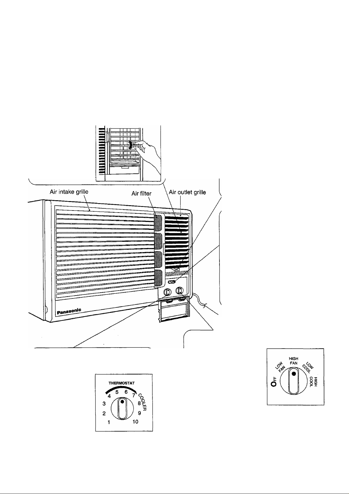
CW-C200SR, CW-C240SR
-
-----------------------------------
----------------
-------------------------------
Vertical Airflow Direction Vane (Airflow direction adjustment Up-and"Down)
Ventilation Lever
When the slide lever is at the:
CLOSE-4 VENT OPEN
The vertical airflow
direction vane is
controlled by posi
tioning the vane to
discharge the air
upwards, downwards
or straight out.
Vertical airflow direction
adjustment louvers
“OPEN” position, the vent, door
opens to allow air, smoke or odours
to be expelled from the room.
CLOSE 4 VENT ►OPEN
“CLOSE” position, the vent, door
is closed and the air inside the room
is circulated and conditioned.
Air Swing Switch
AIR SWING
OFF
OFF
Stops the operation of Air Swing.
ON
Thermostat Control Knob
When you turn the
Thermostat Control
Knob to the desired
setting, the thermo
stat will automatically
control the tempe
rature of the indoor
air. The further clockwise you turn the
knob, the cooler the indoor air will become.
ON
Air Swing is in operation.
Power supply cord
Main Control Knob
OFF
Stops all operations.
LOW FAN
Fan only operation without
cooling at low fan speed.
HIGH FAN
Fan only operation without
cooling at high fan speed.
(fan only operation recir
culates filtered room air).
LOW COOL
Cooling operation at low fan speed.
HIGH COOL
Cooling operation at high fan speed.
-2-
Page 4
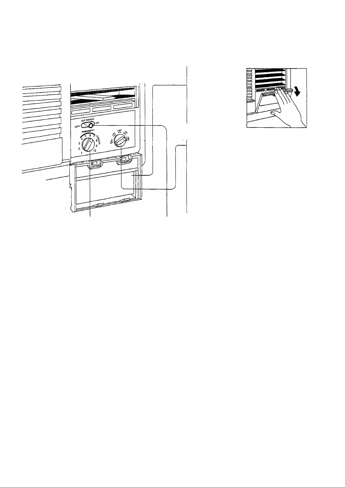
CW-C200SR, CW-C240SR (Cooling Only)
2. open the
cover.
3. Main Control Knob
Set to either LOW COOL or HIGH COOL as
required. (FAN setting operates the fan only.)
Caution; if the Main Control Knob is turned off
or changed to a fan setting from a cooling
operation setting, WAIT at least 3 minutes
before resetting to a cooling operation.
1. Power Supply
Set the Main Control Knob to the OFF
position; confirnn that the Power Supply
Cord is connected to a proper AC outlet.
<240-220V, 50Hz>
Recommended
Use ihe air conditioner
under the following
conditions;
• When humidity does not exceed 90% and
room temperature is above 21 '"C.
4. Thermostat Control Knob
Set the Thermostat Control Knob at the desired
setting. (Usually “6 ~ T is a recommended
setting position.) If the room temperature is
unsatisfactory after a reasonable amount of
time, turn the control knob clockwise to cool the
room more. Or anti-clockwise to cool the room
less.
• When the Thermostat Control knob is set to
“10”, moisture may freeze onto the coils and
prevent effective cooling. If this happens, turn
the knob to High Fan, and the thermostat
control anti-clockwise. This will quickly defrost
the cooling coil so that normal cooling can be
resumed.
5. Air Swing Switch
(Airflow direction adjustment
Side-to-Side)
Continuous operation at over 90% humidity
may create condensation and waterdrops on
the intake and outlet vents.
For fixed side-to-side air direction, set the Air
Swing Switch to “ON” until the desired air
direction is obtained, then move It to “OFF”.
For continuous side-to-side air circulation, set
the Air Swing Switch to “ON” and leave it there.
-3-
Page 5

CW-A200SR, CW-A240SR
..
.
Vertical Airflow Direction Vane
(Airflow direction adjustment
Up-and-Down)
Ventilation Lever
When the slide lever is at the:
L
CLOSED VENT > OPEN
The vertical airflow
direction vane is
controlled by posi
tioning the vane to
discharge the air
upwards, downwards or
straight out.
Vertical airflow direction
adjustment louvers
“OPEN” position, the vent, door
opens to allow air, smoke or odours
to be expelled from the room.
CLOSE ^VENT^ OPEN
“CLOSE” position, the vent, door
is closed and the air inside the room
is circulated and conditioned.
Air Swing Switch
AtR SWING
OFF
OFF
Stops the operation of Air Swing.
ON
f Thermostat Control Knob
When you turn the
Thermostat Control
Knob to the desired
setting, the thermo
stat will automatically
control the tempe
rature of the indoor
air. The further clockwise or anticlockwise
you turn the knob, the cooler or warmer the
indoor air will become.
THERMOSTAT
WARMER
COOLER
ON
Air Swing is in operation.
Power supply cord
Main Control Knob
OFF
Stops all operations.
FAN
Selects fan speed.
LOW COOL
Air cooling operation at low
fan speed.
HIGH COOL
Air cooling operation at high fan speed.
LOW HEAT
Air heating operation at low fan speed.
HIGH HEAT
Air heating operation at high fan speed.
HEATING COOLING
FAN FAN
/
LOW
\
HIGH
Off
I
LOW
;
-4-
Page 6
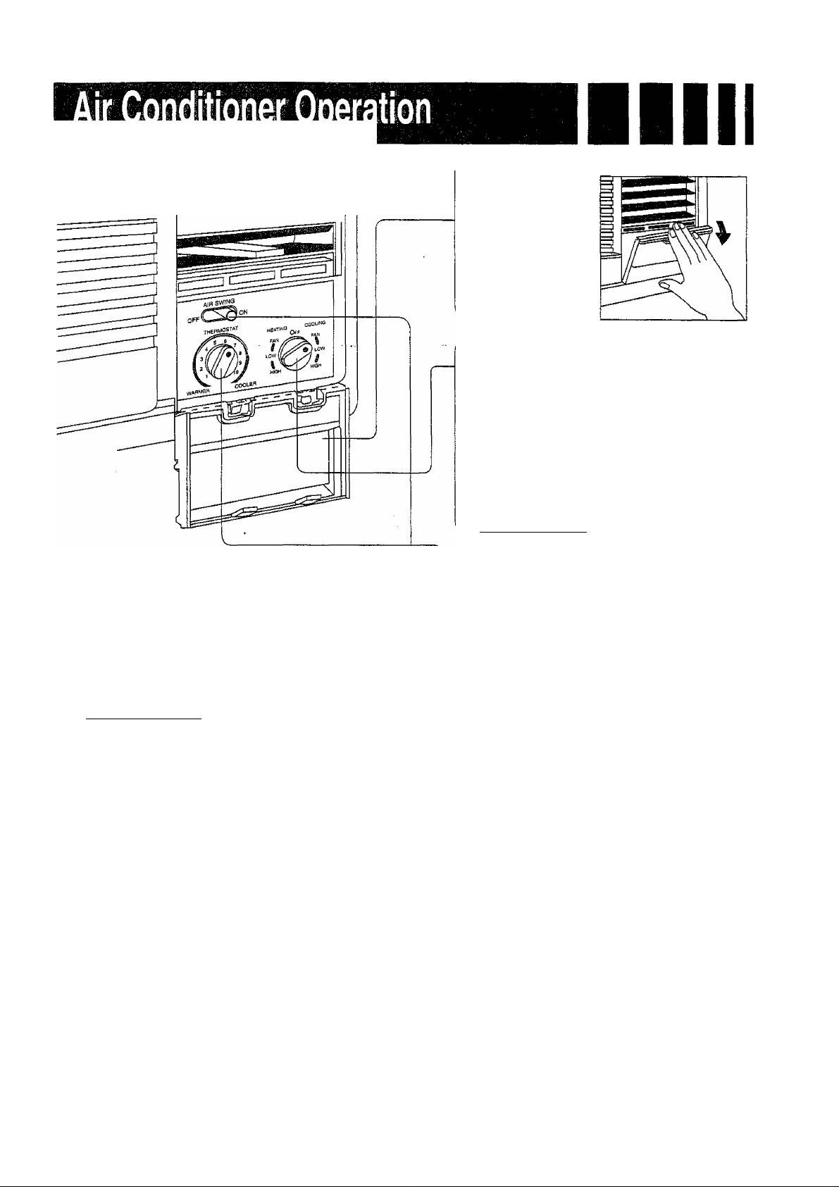
CW-A200SR, CW-A240SR (Cooling And Heating)
2. Open the
cover.
3. Main Control Knob
Set to either LOW COOL, HIGH COOL, LOW
HEAT or HIGH HEAT. (Fan permits fan
operation without cooling or heating)
* Caution: If the Main Control Knob is turned
off or turned to a fan only setting from a
cooling operation setting, WAIT at least 3
minutes before resetting to a cooling or
heating operation.
_______________________
J
1. Power Supply
Set the Main Control Knob to the OFF
position; confirm that the Power Supply
Cord is connected to a proper AC outlet.
<240-220V, 5QHz>
________________
Recommendeci
Use the air conditioner
under the following
conditions:
• When humidity does not exceed 90% and
room temperature is above 21 °C,
4. Thermostat Control Knob
Set the Thermostat Control Knob to the desired
setting. (Usually “4 - 5” is a recommended
setting for heating, and “6 ^ 7” for cooling.) If the
room temperature is unsatisfactory after a
reasonable amount of time, turn the control
knob anticlockwise to make the room warmer,
or clockwise to make the room cooler.
• When the Thermostat Control Knob is set to
“10”, moisture may freeze onto the colls and
prevent effective cooling. If this happens, turn
the Main Control Knob to FAN, and turn the
Thermostat Control Knob anticlockwise. This
will quickly defrost the cooling coil and allow
normal cooling.
5. Air Swing Switch
(Airfiow direction adjustment
Side-to-Side)
Continuous operation at over 90% humidity
may create condensation and waterdrops on
the intake and outlet vents.
For fixed side-to-side air direction, set the Air
Swing Switch to “ON” until the desired air
direction is obtained, then move it to “OFF”.
For continuous side-to-side air circulation, set
the Air Swing Switch to “ON” and leave it there.
-5-
Page 7
y j i y # ! i i [ i i i e i i e
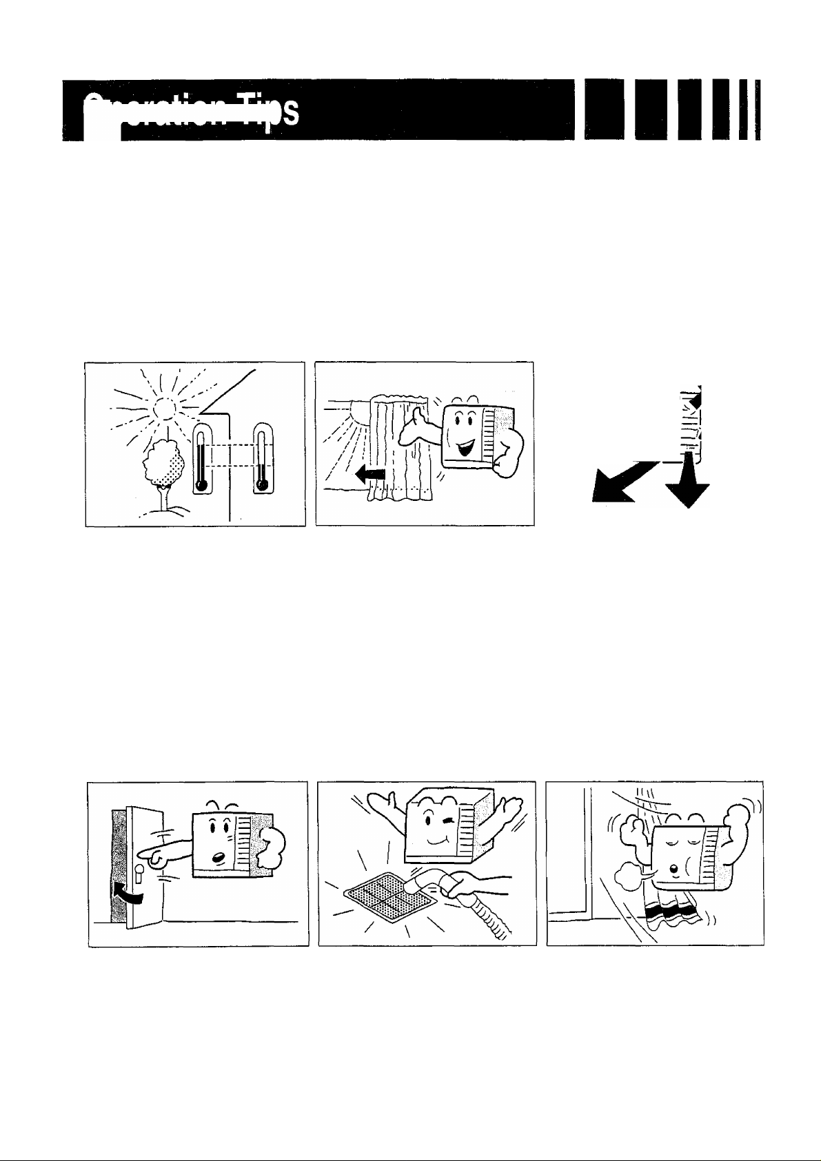
Operation for comfort and economy
Do not overcool the room.
This is not good for health and
waste eiectricity.
Keep blinds or curtains
closed.
Do not let sunshine enter
the room directly when the air
conditioner is in operation.
Keep the room temperature uniform.
Adjust the vertical and horizontal
airflow direction to ensure a
uniform temperature in the room.
mm
Make sure that the doors and Clean the air filter regularly,
windows are shut tight. Blockages in the air filter reduce
Avoid opening doors and windows *1’®
as much as possible to keep the dehumidrfying effects. Clean at
cool air in the room.
(See page 8).
Ventilate the room
occasionally.
Since windows are kept closed, it
is a good idea to open them and
ventilate the room now and then.
-6-
Page 8
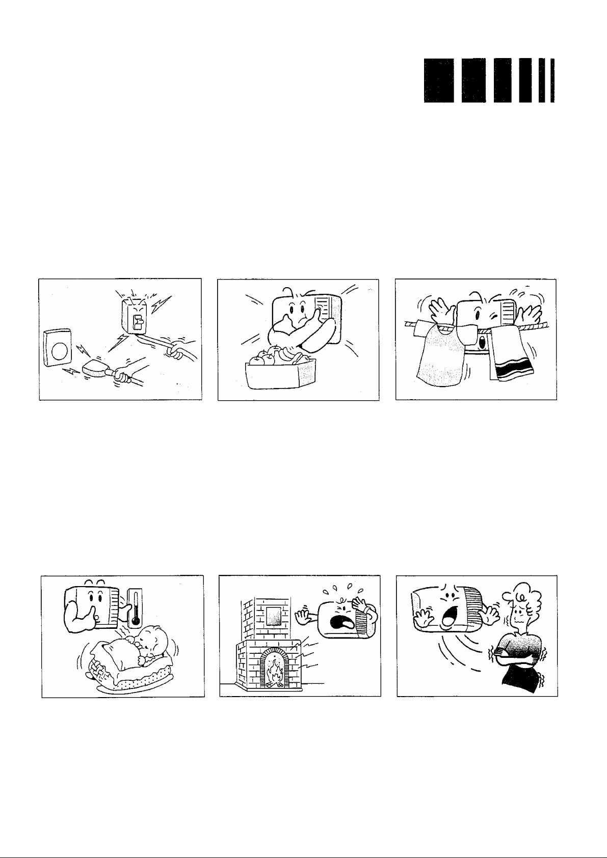
Do noî pull ouï the power
cord.
Damage to the cord may result in
serious eiecthcai shocks.
Do not use the air
conditioner for purposes
other than cooling the room.
Do not use the air conditioner for
other purposes such as drying
clothes, preserving foods, keeping
animals, or cultivating vegetables.
Do not block the air intake
and outlet vents.
This causes lowered performance
and irregular operation. Do not
insert sticks or other objects into
these vents as it is dangerous to
touch the electric components and
the fan.
Select the most appropriate
temperature.
Take care to adjust the temperature
to suit the conditions. Rooms
occupied by infants, the elderly,
or the sick should be kept at an
appropriate temperature.
Do not use heating
apparatuses in the vicinity.
The air conditioner’s plastic parts
melt if exposed to excessive heat.
Avoid exposing the body
directly to a continuous
unidirectional airflow for
long periods.
This is not recommended for
health reasons.
-7-
Page 9
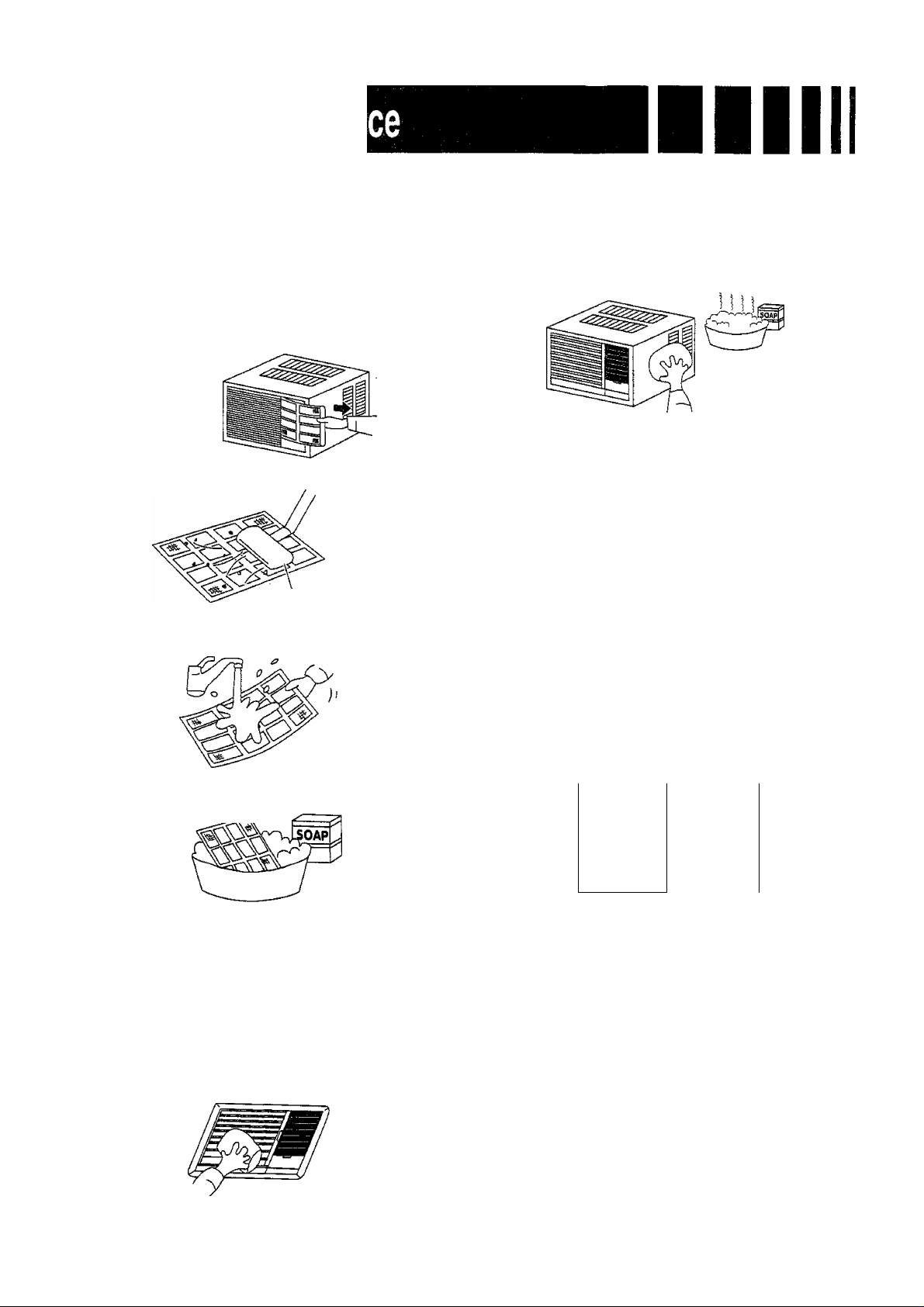
Always turn off the air conditioner and main power supply before cleaning to ensure safety.
Air Filter
The air filter behind the intake grille should be washed
at least every two weeks or as often as it needs
cleaning.
HOW TO CLEAN THE ASR FILTER
1. To remove the air filter, grasp the tab on the filter
and pull to the right.
2. Vacuum the filter on the dusty side to remove light
dust.
Vacuum cleaner
3. Wash the filter, cleaner side up under gently flowing
water to wash out accumulated dust and lint.
Cabinet
Clean the cabinet with mild soap or detergent and
lukewarm water.
lukewarm water -t-
mild detergent
Caution
Wipe off dirt with a soft, dry cloth (use a vacuum
cleaner to remove dust from the air inlet.) Use a
cloth and water less than 40“C to remove stubborn
dirt (the cloth should be well-wrung). Do not use
the following cleansers as they cause the paint to
peel and lead to malfunctions; Benzene, thinner,
scouring powder, chemical-soaked cloths, etc.
4. If the filter is very dirty, use a mild household
detergent in the wash water.
Let the filter dry thoroughly before reinstalling it.
When reinstalling the filter, be sure the word “FRONT’
is facing you as you slide the filter back into place.
Front Grille
Clean the front grille with a clean cloth lightly dampe
ned with mild liquid dish-washing detergent.
Thinner
Benzene
Annual check
* After long-term usage of room air conditioners, dust
and dirt will accumulate inside, lowering the
performance. This may cause the generation of
odour or may impede the drainage of the dehumidifying
water.
* Besides regular cleaning of the air conditioner, a
separate annual check Is also recommended
(chargeable). Please request your dealer to carry out
these checks.
-8-
Page 10
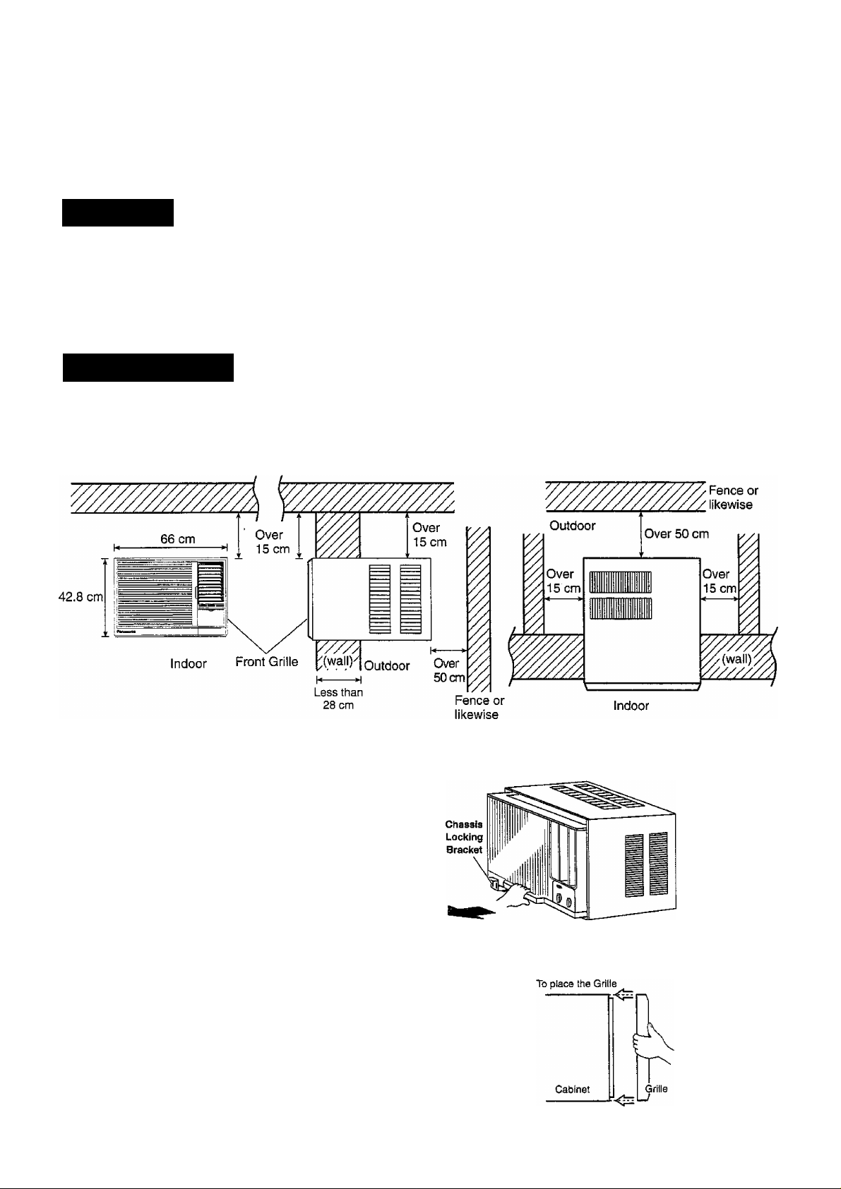
Please read the following before installing the Air Conditioner.
Select the Best Location for the most efficient cooling.
Location
® The air conditioner should be installed in a dry place where there are no draughts.
• Condensation from the air conditioner must be drained to an appropriate location.
• Do not install in a location where flammable gas leaks are a possibility.
• Using in locations where the air is salty such as beside the sea or near hot spas, or
where sulphurous gas is generated, may lead to a malfunction. Please consult your dealer.
• Ensure that the wall is strong enough to support the unit.
How to Instal l
There should not be any obstacles surrounding the unit.
Prepare the installation hole slightly bigger than cabinet size.
(FRONT VIEW)
1) PREPARE CHASSIS
• Remove chassis locking bracket by loosening
the screw.
• Slide the chassis out from the cabinet.
2) Place cabinet into opening and secure it by wood
screws or nails.
• The cabinet should be installed tilted slightly
lower to the rear for nescessary condensate
drainage. (Max. 10mm)
3) Slide Chassis into the cabinet which installed the
above 2).
• The tubings or ducting part should not be touched
with the cabinet.
4) Lock the chassis into cabinet by chassis locking
bracket.
5) Place FRONT GRILLE onto CABINET by screws.
• To place the grille, hook top of grille onto top of
cabinet, push bottom of grille in until it snaps
into place. Secure the Front Grille with the
screws at the right, left and centre of the grille.
Ceiling
(SIDE VIEW)
(TOP VIEW)
-9-
Page 11
Electrical work
Noise considerations
• Always use at the rated voltage.
• Some installation locations may require installation of
a shortcircuit breaker.
• A16 Ampere (CW-C200SR, CW-A200SR), 20 Ampere
(CW-C240SR, CW-A240SR) time delay fuse or circuit
breaker is required.
• Nominal cross sectional area of power supply wire
must be 3 core x 1.5 mm^ {CW-C200SR, CW-A200SR)
and 3 core x 2.5 mm^ (CW-C240SR, CW-A240SR) or
above.
• The power supply must be from an independent circuit.
® All electrical installation must be made in
accordance with local wiring and safety regulations
wherever applicable.
• Please consult your dealer concerning installation
requirements.
Transferring
When repositioning the air conditioner due to
renovations, or when transferring to a different
location, the removal and réinstallation of the unit
requires an additional service charge. Please consult
your dealer before moving.
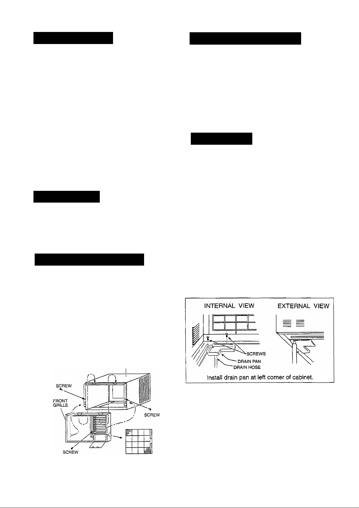
Rernqval of the grilie
1) REMOVE AIR FILTER
2) REMOVE FRONT GRILLE
• Loosen the screws at the right, left and centre of the
grille.
• Press the side of the cabinet firmly and at the same
time pull the corner of the grille forward to
unhook the tabs.
• Slide the grille upward to free the two tabs at the
top of the grille from slots at the top of the cabinet.
• Select an installation location that can support the
weight of the air conditioner and one that will not cause
increased operating noise and vibration.
• Ensure that airflow and noise from the rear side
of the unit (outdoors) when installed do not cause
inconvenience to neighbouring residents.
• Obstacles placed in front of the air outlet on the
rear side of the unit (outdoors), or covers placed
over it, cause excessive noise and a deterioration in
performance.
Drain water
To get the maximum cooling efficiency this air
conditioner is designed to splash the condensate
on the condenser coil.
This method is called “Slinger-Up System”. (For cooling
model only)
If the splashing sound annoys you, you can provide
an outside drain by using the following procedure
which may, however cause a small loss of
performance.
1. Slide out the chassis from the cabinet.
2. Remove the rubber plug from the body base plate.
(For cooling model only)
3. Install the drain pan prepared in the accessory kit to
the corner of the cabinet with 2 screws.
4. Connect the drain hose to the outlet on the drain pan
bottom.
5. Slide the chassis into its original place in the cabinet.
Note: Drain hose or tubing can be purchased locally to
satisfy your particular needs.
CABINET
-10-
Page 12
Check the following points before requesting for repairs or service. If the malfunction persists, please contact your dealer.
FaUiMs
Does not operate.
Does not cool or heat effectively.
The room has a peculiar odour.
• Has the fuse blown or has the circuit breaker been tripped?
• Is the Main Control Knob set at Off?
Is the air filter dirty? See air filter cleaning Instructions on page 8.
Are the air intake and outlet vents on the rear side of the unit
(outdoors) blocked?
Is the air conditioner set for ventilation (the ventilation lever set
at Open) or is the Main Control Knob set at either High Fan or
Low Fan?
The Thermostat Control Knob may not be set low enough. Turn
the knob further clockwise: the indoor air should become cooler or
warmer.
The room may have been very hot when the air conditioner
was first turned on. Allow time for it to cool down or heat up.
The cooling coils have iced up. To melt the ice, turn the Main Control
Knob to FAN and the Thermostat Control Knob anti-clockwise.
Check that this is not a damp smell exuded by the walls, carpet,
furniture or cloth items in the room.
Air conditioner operation is
noisy.
It seems that condensation is
leaking from the air conditioner.
For a noise that sounds like water flowing:
This is the sound of freon circulating inside the air conditioner unit.
For a noise that sounds like a shower:
This is the sound of the dehumidifying water being processed
inside the air conditioning unit.
Condensation occurs when the airflow from the air conditioner
cools the warm room air.
-11 -
Page 13

Turn off the power as soon as any of
the following events occur and
The circuit breaker is frequently tripped or the
fuse is frequently blown.
contact your dealer.
Control knob operation is not normal.
if water or foreign objects have accidentally
entered the air conditioner.
If there is abnormal sound during operation.
WARNING
(1) REMOVE POWER PLUG OR DISCONNECT FROM THE MAINS BEFORE SERVICING THIS APPLIANCE.
(2) THIS APPLIANCE MUST BE EARTHED.
IMPORTANT
1. WHEN THE POWER CORD IS CONNECTED TO THE MAINS THROUGH A MULTI POLAR SWITCH
THERE MUST BE A MULTI POLAR SWITCH (DISCONNECTING MEANS) WITH A MINIMUM 3mm
CONTACT GAP IN THE FIXED INSTALLATION CIRCUIT.
2. WHEN THE POWER PLUG IS CONNECTED TO THE RECEPTACLE
The wires in this main lead are coloured in accordance with the following code:
Green-and-yeilow ; Earth
Blue : Neutral
Brown : Live
If the colours of the wires in the main lead of this appliance do not correspond with the coloured markings
indentifying the terminals in your plug, proceed as follows:
The green-and-yellow wire must be connected to the terminal in the plug which is marked with letter E or by
the earth symbol © or coloured green or green-and-yellow.
The blue wire must be connected to the terminal which is marked with the letter N or coloured black.
The brown wire must be connected to the terminal which is marked with the letter L or coloured red.
NOTE
IF THE SUPPLY CORD IS DAMAGED. IT MUST BE REPLACED WITH A SPECIAL CORD OBTAINABLE AT
AUTHORIZED SERVICE/PARTS CENTERS.
-12-
Page 14

Note
Please remember to record the following:
______________ _
Model Number
Serial Number
• Dealer’s Name
Date Purchased
F561199
Matsushita Electric Industrial Co., Ltd
Central P.O. Box 288, Osaka 530-91, Japan
Printed in Malaysia
I F9604-1 1
 Loading...