

Panasonic CS-HZ9RKE, CS-HZ12RKE, CU-HZ9RKE, CS-HZ9RKE-4, CU-HZ12RKE Service Manual
...
© Panasonic Corporation 2015.
Order No: PAPAMY1507114CE
CLOCK
MODE
AIR CONDITIO NE R
OFF/ON
SET CHECK RESET
AC
RC
ON
OFF
SET
CANCEL
123
TIMER
ECONAVI
+8/10°C
HEAT
MODE
TEMP
FAN SPEED
AIR SWING
POWERFUL/QUIET
+8/10°C
HEAT
Indoor Unit Outdoor Unit
CS-HZ9RKE
CS-HZ12RKE
CS-HZ9RKE-4
CS-AZ9RKE
CU-HZ9RKE
CU-HZ12RKE
CU-HZ9RKE-4
CU-AZ9RKE
Destination
North Europe
CAUTION
R32 REFRIGERANT
– This Air Conditioner contains and operates with refrigerant R32.
THIS PRODUCT MUST ONLY BE INSTALLED OR SERVICED BY QUALIFIED PERSONNEL.
Refer to Commonwealth, State, Territory and local legislation, regulations, codes, installation & operation manuals, before the
installation, maintenance and/or service of this product.
WARNING
This service information is designed for experienced repair technicians only and is not designed for use by the general public.
It does not contain warnings or cautions to advise non-technical individuals of potential dangers in attempting to service a product.
Products powered by electricity should be serviced or repaired only by experienced professional technicians. Any attempt to
service or repair the product or products dealt with in this service information by anyone else could result in serious injury or death.

2
TABLE OF CONTENTS
1. Safety Precautions ............................................. 3
2. Precaution For Using R32 Refrigerant ............. 6
3. Specification ..................................................... 10
4. Features ............................................................. 16
5. Location of Controls and Components .......... 17
5.1 Indoor Unit .................................................. 17
5.2 Outdoor Unit ............................................... 17
5.3 Remote Control .......................................... 17
6. Dimensions ....................................................... 18
6.1 Indoor Unit .................................................. 18
6.2 Outdoor Unit ............................................... 19
7. Refrigeration Cycle Diagram ........................... 20
8. Block Diagram .................................................. 21
8.1 Indoor Power Supply Connection ............... 21
8.2 Outdoor Power Supply Connection ............ 22
9. Wiring Connection Diagram ............................ 23
9.1 Indoor Unit .................................................. 23
9.2 Outdoor Unit ............................................... 24
10. Electronic Circuit Diagram .............................. 25
10.1 Indoor Unit .................................................. 25
10.2 Outdoor Unit ............................................... 26
11. Printed Circuit Board ....................................... 27
11.1 Indoor Unit .................................................. 27
11.2 Outdoor Unit ............................................... 29
12. Installation Instruction ..................................... 30
12.1 Select The Best Location ........................... 30
12.2 Indoor Unit .................................................. 31
12.3 Outdoor Unit ............................................... 37
13. Operation and Control ..................................... 41
13.1 Basic Function ............................................ 41
13.2 Indoor Fan Motor Operation ....................... 42
13.3 Outdoor Fan Motor Operation .................... 43
13.4 Airflow Direction .......................................... 43
13.5 Quiet operation (Cooling Mode/Cooling area
of Dry Mode) ............................................... 45
13.6 Quiet operation (Heating) ........................... 45
13.7 Powerful Mode Operation ........................... 46
13.8 Timer Control .............................................. 46
13.9 Auto Restart Control ................................... 46
13.10 Indication Panel .......................................... 47
13.11 ECONAVI Operation .................................. 48
13.12 +8/10°C Heat Operation ............................. 52
14. Protection Control ............................................ 53
14.1 Protection Control For All Operations ......... 53
14.2 Protection Control For Cooling & Soft Dry
Operation .................................................... 55
14.3 Protection Control For Heating Operation .. 56
15. Servicing Mode ................................................. 58
15.1 Auto OFF/ON Button .................................. 58
15.2 Remote Control Button ...............................59
16. Troubleshooting Guide ....................................60
16.1 Refrigeration Cycle System ........................60
16.2 Breakdown Self Diagnosis Function ...........62
16.3 Error Code Table ........................................63
16.4 Self-diagnosis Method ................................65
17. Disassembly and Assembly Instructions ......93
17.1 Indoor Unit ..................................................93
17.2 Outdoor Electronic Controller Removal
Procedure ...................................................98
18. Technical Data ..................................................99
18.1 Cool Mode Performance Data ....................99
18.2 Heat Mode Performance Data ................. 100
19. Service Data ................................................... 101
19.1 Cool Mode Outdoor Air Temperature
Characteristic ........................................... 101
19.2 Heat Mode Outdoor Air Temperature
Characteristic ........................................... 103
19.3 Piping Length Correction Factor .............. 105
20. Exploded View and Replacement Parts List 106
20.1 Indoor Unit ............................................... 106
20.2 Outdoor Unit ............................................ 111
3
1. Safety Precautions
Read the following “SAFETY PRECAUTIONS” carefully before perform any servicing.
Electrical work must be installed or serviced by a licensed electrician. Be sure to use the correct rating of the power plug and
main circuit for the model installed.
The caution items stated here must be followed because these important contents are related to safety. The meaning of each
indication used is as below. Incorrect installation or servicing due to ignoring of the instruction will cause harm or damage,
and the seriousness is classified by the following indications.
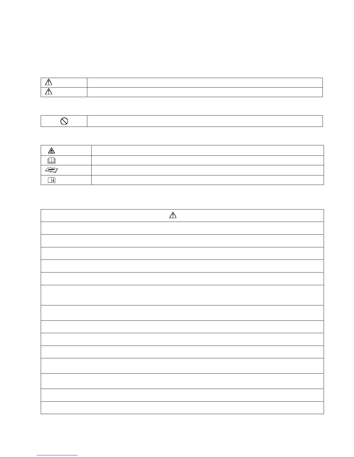
WARNING
This indication shows the possibility of causing death or serious injury.
CAUTION
This indication shows the possibility of causing injury or damage to properties.
The items to be followed are classified by the symbols:
This symbol denotes item that is PROHIBITTED from doing.
Explanation of symbols displayed on the indoor unit or outdoor unit.
WARNING
This symbol shows that this equipment uses a flammable refrigerant.
If the refrigerant is leaked, together with an external ignition source, there is a possibility of ignition.
CAUTION
This symbol shows that the Operation Instructions should be read carefully.
CAUTION
This symbol shows that a service personnel should be handling this equipment with reference to the
Installation Instructions.
CAUTION
This symbol shows that there is information included in the Operation Instructions and/or Installation Instructions.
Carry out test run to confirm that no abnormality occurs after the servicing. Then, explain to user the operation, care and
maintenance as stated in instructions. Please remind the customer to keep the operating instructions for future reference.
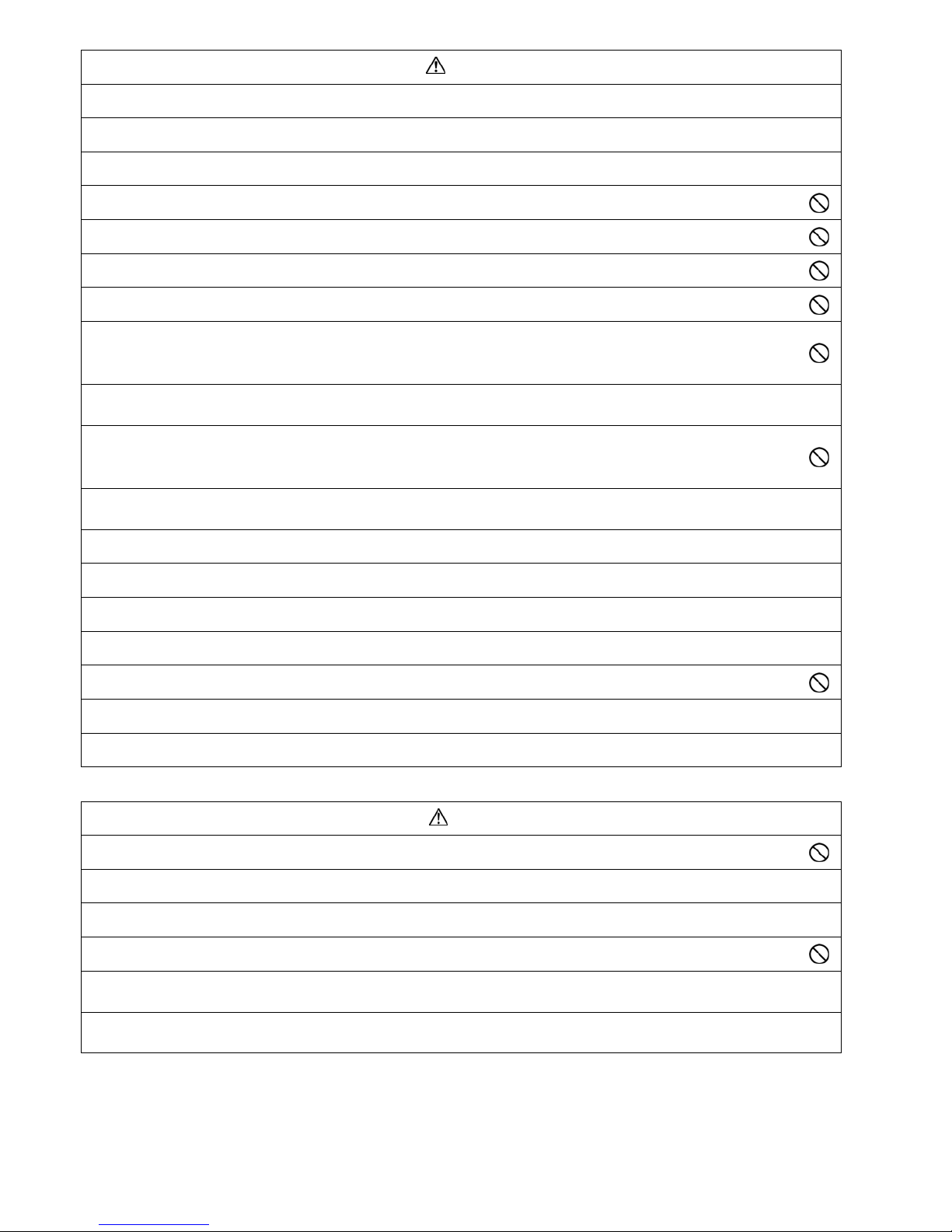
WARNING
1. Do not modify the machine, part, material during repairing service.
2. If wiring unit is supplied as repairing part, do not repair or connect the wire even only partial wire break. Exchange the whole wiring unit.
3. Do not wrench the fasten terminal. Pull it out or insert it straightly.
4.
Engage authorized dealer or specialist for installation and servicing. If installation or servicing done by the user is defective, it will cause
water leakage, electrical shock or fire.
5. Install according to this installation instructions strictly. If installation is defective, it will cause water leakage, electrical shock or fire.
6.
The appliance shall be stored in a well ventilated room with floor area larger than 2.06 m
2
and without any continuously operating ignition
sources.
Keep away from open flames, any operating gas appliances or any operating electric heater. Else, it may explode and cause injury or
death.
7.
The appliance shall be installed, and/or operated in a room with floor area larger than 2.06 m
2
and keep away from ignition sources, such
as heat/sparks/open flame, or, hazardous areas, such as gas appliances, gas cooking, reticulated gas supply systems, or electric cooking
appliances, etc.
8.
Use the attached accessories parts and specified parts for installation and servicing. Otherwise, it will cause the set to fall, water leakage,
fire or electrical shock.
9.
Install at a strong and firm location which is able to withstand the set's weight. If the strength is not enough or installation is not properly
done, the set will drop and cause injury.
10.
For electrical work, follow the local national wiring standard, regulation and the installation instruction. An independent circuit and single
outlet must be used. If electrical circuit capacity is not enough or defect found in electrical work, it will cause electrical shock or fire.
11.
This equipment is strongly recommended to be installed with Earth Leakage Circuit Breaker (ELCB) or Residual Current Device (RCD),
with sensitivity of 30mA at 0.1 sec or less. Otherwise, it may cause electrical shock and fire in case equipment breakdown or insulation
breakdown.
12.
Do not use joint cable for indoor/outdoor connection cable. Use the specified indoor/outdoor connection cable, refer to installation
instruction CONNECT THE CABLE TO THE INDOOR UNIT and connect tightly for indoor/outdoor connection. Clamp the cable so that no
external force will be acted on the terminal. If connection or fixing is not perfect, it will cause heat up or fire at the connection.
13.
Wire routing must be properly arranged so that control board cover is fixed properly. If control board cover is not fixed perfectly, it will
cause heat-up or fire at connection point of terminal, fire or electrical shock.
14. Do not tie up the power supply cord into a bundle by band. Abnormal temperature rise on power supply cord may happen.
4
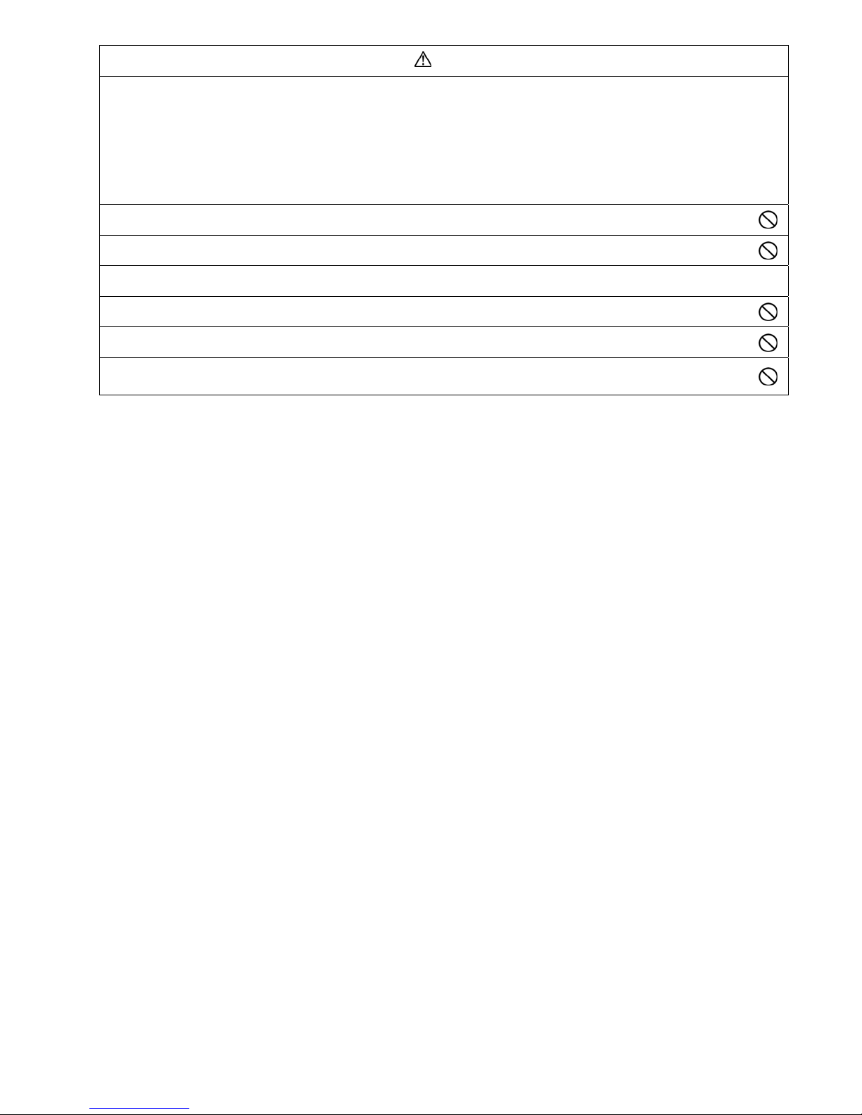
WARNING
15.
When install or relocate air conditioner, do not let any substance other than the specified refrigerant, eg. air etc. mix into refrigeration
cycle (piping). (Mixing of air etc. will cause abnormal high pressure in refrigeration cycle and result in explosion, injury etc.).
16.
Do not install outdoor unit near handrail of veranda. When installing air-conditioner unit at veranda of high rise building, child may climb
up to outdoor unit and cross over the handrail and causing accident.
17.
Do not pierce or burn as the appliance is pressurized. Do not expose the appliance to heat, flame, sparks, or other sources of ignition.
Else, it may explode and cause injury or death.
18.
This equipment must be properly earthed. Earth line must not be connected to gas pipe, water pipe, earth of lightning rod and
telephone. Otherwise, it may cause electrical shock in case equipment breakdown or insulation breakdown.
19. Keep away from small children, the thin film may cling to nose and mouth and prevent breathing.
20.
Do not use unspecified cord, modified cord, joint cord or extension cord for power supply cord. Do not share the single outlet with
other electrical appliances. Poor contact, poor insulation or over current will cause electrical shock or fire.
21.
Tighten the flare nut with torque wrench according to specified method. If the flare nut is over-tightened, after a long period, the
flare may break and cause refrigerant gas leakage.
22.
For R32 model, use piping, flare nut and tools which is specified for R32 refrigerant. Using of existing (R22) piping, flare nut
and tools may cause abnormally high pressure in the refrigerant cycle (piping), and possibly result in explosion and injury.
Thickness or copper pipes used with R32 must be more than 0.8 mm. Never use copper pipes thinner than 0.8 mm.
It is desirable that the amount of residual oil less than 40 mg/10 m.
23.
During installation, install the refrigerant piping properly before run the compressor. (Operation of compressor without fixing refrigeration
piping and valves at opened condition will cause suck-in of air, abnormal high pressure in refrigeration cycle and result in explosion, injury
etc.).
24.
Do not perform flare connection inside a building or dwelling or room, when joining the heat exchanger of indoor unit with
interconnecting piping. Refrigerant connection inside a building or dwelling or room must be made by brazing or welding. Joint
connection of indoor unit by flaring method can only be made at outdoor or at outside of a building or dwelling or room. Flare
connection may cause gas leak and flammable atmosfere.
25.
During pump down operation, stop the compressor before remove the refrigeration piping. (Removal of refrigeration piping while
compressor is operating and valves are opened condition will cause suck-in of air, abnormal high pressure in refrigeration cycle and result
in explosion, injury etc.).
26.
After completion of installation or service, confirm there is no leakage of refrigerant gas. It may generate toxic gas when the refrigerant
contacts with fire.
27. Ventilate if there is refrigerant gas leakage during operation. It may cause toxic gas when the refrigerant contacts with fire.
28.
Do not use means to accelerate the defrosting process or to clean, other than those recommended by the manufacturer. Any unfit method
or using incompatible material may cause product damage, burst and serious injury.
29. Be aware that refrigerants may not contain an odour.
30. Do not insert your fingers or other objects into the unit, high speed rotating fan may cause injury.
31. Must not use other parts except original parts describe in catalog and manual.
32. Do not add or replace refrigerant other than specified type. It may cause product damage, burst and injury etc.
CAUTION
1.
Do not install the unit at place where leakage of flammable gas may occur. In case gas leaks and accumulates at surrounding of
the unit, it may cause fire.
2.
Carry out drainage piping as mentioned in installation instructions. If drainage is not perfect, water may enter the room and damage the
furniture.
3.
Tighten the flare nut with torque wrench according to specified method. If the flare nut is over-tightened, after a long period, the flare may
break and cause refrigerant gas leakage.
4. Do not touch outdoor unit air inlet and aluminium fin. It may cause injury.
5.
Select an installation location which is easy for maintenance.
Incorrect installation, service or repair of this air conditioner may increase the risk of rupture and this may result in loss damage or injury
and/or property.
6.
Pb free solder has a higher melting point than standard solder; typically the melting point is 50°F - 70°F (30°C - 40°C) higher.
Please use a high temperature solder iron. In case of the soldering iron with temperature control, please set it to 700 ± 20°F (370 ± 10°C).
Pb free solder will tend to splash when heated too high (about 1100°F / 600°C).
5
CAUTION
7.
Power supply connection to the room air conditioner.
Use power supply cord 3 × 1.5 mm
2
type designation 60245 IEC 57 or heavier cord.
Connect the power supply cord of the air conditioner to the mains using one of the following method.
Power supply point should be in easily accessible place for power disconnection in case of emergency.
In some countries, permanent connection of this air conditioner to the power supply is prohibited.
1) Power supply connection to the receptacle using power plug.
Use an approved 15/16A power plug with earth pin for the connection to the socket.
2) Power supply connection to a circuit breaker for the permanent connection.
Use an approved 16A circuit breaker for the permanent connection. It must be a double pole switch with a minimum 3.0 mm contact
gap.
8.
Do not release refrigerant during piping work for installation, servicing, reinstallation and during repairing a refrigerant parts.
Take care of the liquid refrigerant, it may cause frostbite.
9. Prevent liquid or vapor from entering sumps or sewers since vapor is heavier than air and may form suffocating atmospheres.
10. Installation or servicing work: It may need two people to carry out the installation or servicing work.
11. Do not install this appliance in a laundry room or other location where water may drip from the ceiling, etc.
12. Do not sit or step on the unit, you may fall down accidentally.
13.
Do not touch the sharp aluminum fins or edges of metal parts.
If you are required to handle sharp parts during installation or servicing, please wear hand glove.
Sharp parts may cause injury.
6
2. Precaution For Using R32 Refrigerant
The basic installation work procedures are the same as conventional refrigerant (R410A, R22) models.
However, pay careful attention to the following points:
WARNING
1.
Since the working pressure is higher than that of refrigerant R22 models, some of the piping and installation and service tools are
special.
(See “2.1. Special tools for R32 (R410A)”.)
Especially, when replacing a refrigerant R22 model with a new refrigerant R32 model, always replace the conventional piping and flare
nuts with the R32 and R410A piping and flare nuts on the outdoor unit side.
For R32 and R410A, the same flare nut on the outdoor unit side and pipe can be used.
2.
Models that use refrigerant R32 and R410A have a different charging port thread diameter to prevent erroneous charging with
refrigerant R22 and for safety.
Therefore, check beforehand. [The charging port thread diameter for R32 and R410A is 12.7 mm (1/2 inch).]
3.
Be more careful than R22 so that foreign matter (oil, water, etc.) does not enter the piping.
Also, when storing the piping, securely seal the opening by pinching, taping, etc. (Handling of R32 is similar to R410A.)
CAUTION
1.
Installation (Space)
Must ensure the installation of pipe-work shall be kept to a minimum. Avoid use dented pipe and do not allow acute bending.
Must ensure that pipe-work shall be protected from physical damage.
Must comply with national gas regulations, state municipal rules and legislation. Notify relevant authorities in accordance with all
applicable regulations.
Must ensure mechanical connections be accessible for maintenance purposes.
In cases that require mechanical ventilation, ventilation openings shall be kept clear of obstruction.
When disposal of the product, do follow to the precautions in #12 and comply with national regulations.
Always contact to local municipal offices for proper handling.
Interconnecting refrigerant pipework, i.e. pipework external to the unitary components, should be marked with a Class label (see
Figure 9.1 of Code of Practice) every two metres where the pipework is visible. This includes pipework located in a ceiling space
or any void which a person may access for maintenance or repair work within that space.
2.
Servicing
2-1. Service personnel
Any qualified person who is involved with working on or breaking into a refrigerant circuit should hold a current valid certificate
from an industry-accredited assessment authority, which authorizes their competence to handle refrigerants safely in accordance
with an industry recognised assessment specification.
Servicing shall only be performed as recommended by the equipment manufacturer. Maintenance and repair requiring the
assistance of other skilled personnel shall be carried out under the supervision of the person competent in the use of flammable
refrigerants.
Servicing shall be performed only as recommended by the manufacturer.
2-2.
Work
Prior to beginning work on systems containing flammable refrigerants, safety checks are necessary to ensure that the risk of
ignition is minimised.
For repair to the refrigerating system, the precautions in #2-2 to #2-8 must be followed before conducting work on the system.
Work shall be undertaken under a controlled procedure so as to minimize the risk of a flammable gas or vapor being present
while the work is being performed.
All maintenance staff and others working in the local area shall be instructed and supervised on the nature of work being carried
out.
Avoid working in confined spaces.
Wear appropriate protective equipment, including respiratory protection, as conditions warrant.
Ensure that the conditions within the area have been made safe by limit of use of any flammable material. Keep all sources of
ignition and hot metal surfaces away.
2-3. Checking for presence of refrigerant
The area shall be checked with an appropriate refrigerant detector prior to and during work, to ensure the technician is aware of
potentially flammable atmospheres.
Ensure that the leak detection equipment being used is suitable for use with flammable refrigerants, i.e. non sparking, adequately
sealed or intrinsically safe.
In case of leakage/spillage happened, immediately ventilate area and stay upwind and away from spill/release.
In case of leakage/spillage happened, do notify persons downwind of the leaking/spill, isolate immediate hazard area and keep
unauthorized personnel out.
2-4. Presence of fire extinguisher
If any hot work is to be conducted on the refrigeration equipment or any associated parts, appropriate fire extinguishing
equipment shall be available at hand.
Have a dry powder or CO
2 fire extinguisher adjacent to the charging area.
7
CAUTION
2-5. No ignition sources
No person carrying out work in relation to a refrigeration system which involves exposing any pipe work that contains or has
contained flammable refrigerant shall use any sources of ignition in such a manner that it may lead to the risk of fire or explosion.
He/She must not be smoking when carrying out such work.
All possible ignition sources, including cigarette smoking, should be kept sufficiently far away from the site of installation,
repairing, removing and disposal, during which flammable refrigerant can possibly be released to the surrounding space.
Prior to work taking place, the area around the equipment is to be surveyed to make sure that there are no flammable hazards or
ignition risks.
“No Smoking” signs shall be displayed.
2-6. Ventilated area
Ensure that the area is in the open or that it is adequately ventilated before breaking into the system or conducting any hot work.
A degree of ventilation shall continue during the period that the work is carried out.
The ventilation should safely disperse any released refrigerant and preferably expel it externally into the atmosphere.
2-7.
Checks to the refrigeration equipment
Where electrical components are being changed, they shall be fit for the purpose and to the correct specification.
At all times the manufacturer’s maintenance and service guidelines shall be followed.
If in doubt consult the manufacturer’s technical department for assistance.
The following checks shall be applied to installations using flammable refrigerants.
- The charge size is in accordance with the room size within which the refrigerant containing parts are installed.
- The ventilation machinery and outlets are operating adequately and are not obstructed.
- If an indirect refrigerating circuit is being used, the secondary circuit shall be checked for the presence of refrigerant.
- Marking to the equipment continues to be visible and legible. Markings and signs that are illegible shall be corrected.
- Refrigeration pipe or components are installed in a position where they are unlikely to be exposed to any substance which
may corrode refrigerant containing components, unless the components are constructed of materials which are inherently
resistant to being corroded or are properly protected against being so corroded.
2-8. Checks to electrical devices
Repair and maintenance to electrical components shall include initial safety checks and component inspection procedures.
Initial safety checks shall include but not limit to:-
- That capacitors are discharged: this shall be done in a safe manner to avoid possibility of sparking.
- That there is no live electrical components and wiring are exposed while charging, recovering or purging the system.
- That there is continuity of earth bonding.
At all times the manufacturer’s maintenance and service guidelines shall be followed.
If in doubt consult the manufacturer’s technical department for assistance.
If a fault exists that could compromise safety, then no electrical supply shall be connected to the circuit until it is satisfactorily
dealt with.
If the fault cannot be corrected immediately but it is necessary to continue operation, an adequate temporary solution shall be
used.
The owner of the equipment must be informed or reported so all parties are advised thereinafter.
3.
Repairs to sealed components
During repairs to sealed components, all electrical supplies shall be disconnected from the equipment being worked upon prior to
any removal of sealed covers, etc.
If it is absolutely necessary to have an electrical supply to equipment during servicing, then a permanently operating form of leak
detection shall be located at the most critical point to warn of a potentially hazardous situation.
Particular attention shall be paid to the following to ensure that by working on electrical components, the casing is not altered in
such a way that the level of protection is affected. This shall include damage to cables, excessive number of connections,
terminals not made to original specification, damage to seals, incorrect fitting of glands, etc.
Ensure that apparatus is mounted securely.
Ensure that seals or sealing materials have not degraded such that they no longer serve the purpose of preventing the ingress of
flammable atmospheres.
Replacement parts shall be in accordance with the manufacturer’s specifications.
NOTE:
The use of silicon sealant may inhibit the effectiveness of some types of leak detection equipment.
Intrinsically safe components do not have to be isolated prior to working on them.
4.
Repair to intrinsically safe components
Do not apply any permanent inductive or capacitance loads to the circuit without ensuring that this will not exceed the permissible
voltage and current permitted for the equipment in use.
Intrinsically safe components are the only types that can be worked on while live in the presence of a flammable atmosphere.
The test apparatus shall be at the correct rating.
Replace components only with parts specified by the manufacturer. Unspecified parts by manufacturer may result ignition of
refrigerant in the atmosphere from a leak.
5.
Cabling
Check that cabling will not be subject to wear, corrosion, excessive pressure, vibration, sharp edges or any other adverse
environmental effects.
The check shall also take into account the effects of aging or continual vibration from sources such as compressors or fans.
6.
Detection of flammable refrigerants
Under no circumstances shall potential sources of ignition be used in the searching or detection of refrigerant leaks.
A halide torch (or any other detector using a naked flame) shall not be used.
8
CAUTION
7.
Leak detection methods
Electronic leak detectors shall be used to detect flammable refrigerants, but the sensitivity may not be adequate, or may need re-
calibration.
(Detection equipment shall be calibrated in a refrigerant-free area.)
Ensure that the detector is not a potential source of ignition and is suitable for the refrigerant used.
Leak detection equipment shall be set at a percentage of the LFL of the refrigerant and shall be calibrated to the refrigerant
employed and the appropriate percentage of gas (25 % maximum) is confirmed
Leak detection fluids are suitable for use with most refrigerants but the use of detergents containing chlorine shall be avoided as the
chlorine may react with the refrigerant and corrode the copper pipe-work.
If a leak is suspected, all naked flames shall be removed/extinguished.
If a leakage of refrigerant is found which requires brazing, all of the refrigerant shall be recovered from the system, or isolated (by
means of shut off valves) in a part of the system remote from the leak. Oxygen free nitrogen (OFN) shall then be purged through
the system both before and during the brazing process.
8.
Removal and evacuation
When breaking into the refrigerant circuit to make repairs – or for any other purpose – conventional procedures shall be used.
However, it is important that best practice is followed since flammability is a consideration.
The following procedure shall be adhered to:
● remove refrigerant -> ● purge the circuit with inert gas -> ● evacuate -> ● purge again with inert gas ->
● open the circuit by cutting or brazing
The refrigerant charge shall be recovered into the correct recovery cylinders.
The system shall be “flushed” with OFN to render the unit safe.
This process may need to be repeated several times.
Compressed air or oxygen shall not be used for this task.
Flushing shall be achieved by breaking the vacuum in the system with OFN and continuing to fill until the working pressure is
achieved, then venting to atmosphere, and finally pulling down to a vacuum.
This process shall be repeated until no refrigerant is within the system.
When the final OFN charge is used, the system shall be vented down to atmospheric pressure to enable work to take place.
This operation is absolutely vital if brazing operations on the pipe work are to take place.
Ensure that the outlet for the vacuum pump is not close to any ignition sources and there is ventilation available.
9.
Charging procedures
In addition to conventional charging procedures, the following requirements shall be followed.
- Ensure that contamination of different refrigerants does not occur when using charging equipment.
- Hoses or lines shall be as short as possible to minimize the amount of refrigerant contained in them.
- Cylinders shall be kept upright.
- Ensure that the refrigeration system is earthed prior to charging the system with refrigerant.
- Label the system when charging is complete (if not already).
- Extreme care shall be taken not to over fill the refrigeration system.
Prior to recharging the system it shall be pressure tested with OFN (refer to #7).
The system shall be leak tested on completion of charging but prior to commissioning.
A follow up leak test shall be carried out prior to leaving the site.
Electrostatic charge may accumulate and create a hazardous condition when charging and discharging the refrigerant.
To avoid fire or explosion, dissipate static electricity during transfer by grounding and bonding containers and equipment before
charging/discharging.
10.
Decommissioning
Before carrying out this procedure, it is essential that the technician is completely familiar with the equipment and all its details.
It is recommended good practice that all refrigerants are recovered safely.
Prior to the task being carried out, an oil and refrigerant sample shall be taken in case analysis is required prior to re-use of
reclaimed refrigerant.
It is essential that electrical power is available before the task is commenced.
a) Become familiar with the equipment and its operation.
b) Isolate system electrically.
c) Before attempting the procedure ensure that:
mechanical handling equipment is available, if required, for handling refrigerant cylinders;
all personal protective equipment is available and being used correctly;
the recovery process is supervised at all times by a competent person;
recovery equipment and cylinders conform to the appropriate standards.
d) Pump down refrigerant system, if possible.
e) If a vacuum is not possible, make a manifold so that refrigerant can be removed from various parts of the system.
f) Make sure that cylinder is situated on the scales before recovery takes place.
g) Start the recovery machine and operate in accordance with manufacturer’s instructions.
h) Do not over fill cylinders. (No more than 80 % volume liquid charge).
i) Do not exceed the maximum working pressure of the cylinder, even temporarily.
j) When the cylinders have been filled correctly and the process completed, make sure that the cylinders and the equipment are
removed from site promptly and all isolation valves on the equipment are closed off.
k) Recovered refrigerant shall not be charged into another refrigeration system unless it has been cleaned and checked.
Electrostatic charge may accumulate and create a hazardous condition when charging or discharging the refrigerant.
To avoid fire or explosion, dissipate static electricity during transfer by grounding and bonding containers and equipment before
charging/discharging.
9
CAUTION
11.
Labelling
Equipment shall be labelled stating that it has been de-commissioned and emptied of refrigerant.
The label shall be dated and signed.
Ensure that there are labels on the equipment stating the equipment contains flammable refrigerant.
12.
Recovery
When removing refrigerant from a system, either for servicing or decommissioning, it is recommended good practice that all
refrigerants are removed safely.
When transferring refrigerant into cylinders, ensure that only appropriate refrigerant recovery cylinders are employed.
Ensure that the correct number of cylinders for holding the total system charge are available.
All cylinders to be used are designated for the recovered refrigerant and labelled for that refrigerant (i.e. special cylinders for the
recovery of refrigerant).
Cylinders shall be complete with pressure relief valve and associated shut-off valves in good working order.
Recovery cylinders are evacuated and, if possible, cooled before recovery occurs.
The recovery equipment shall be in good working order with a set of instructions concerning the equipment that is at hand and shall
be suitable for the recovery of concerning the equipment that is at hand and shall be suitable for the recovery of flammable
refrigerants.
In addition, a set of calibrated weighing scales shall be available and in good working order.
Hoses shall be complete with leak-free disconnect couplings and in good condition.
Before using the recovery machine, check that it is in satisfactory working order, has been properly maintained and that any
associated electrical components are sealed to prevent ignition in the event of a refrigerant release.
Consult manufacturer if in doubt.
The recovered refrigerant shall be returned to the refrigerant supplier in the correct recovery cylinder, and the relevant Waste
Transfer Note arranged.
Do not mix refrigerants in recovery units and especially not in cylinders.
If compressors or compressor oils are to be removed, ensure that they have been evacuated to an acceptable level to make certain
that flammable refrigerant does not remain within the lubricant.
The evacuation process shall be carried out prior to returning the compressor to the suppliers.
Only electric heating to the compressor body shall be employed to accelerate this process.
When oil is drained from a system, it shall be carried out safely.
10
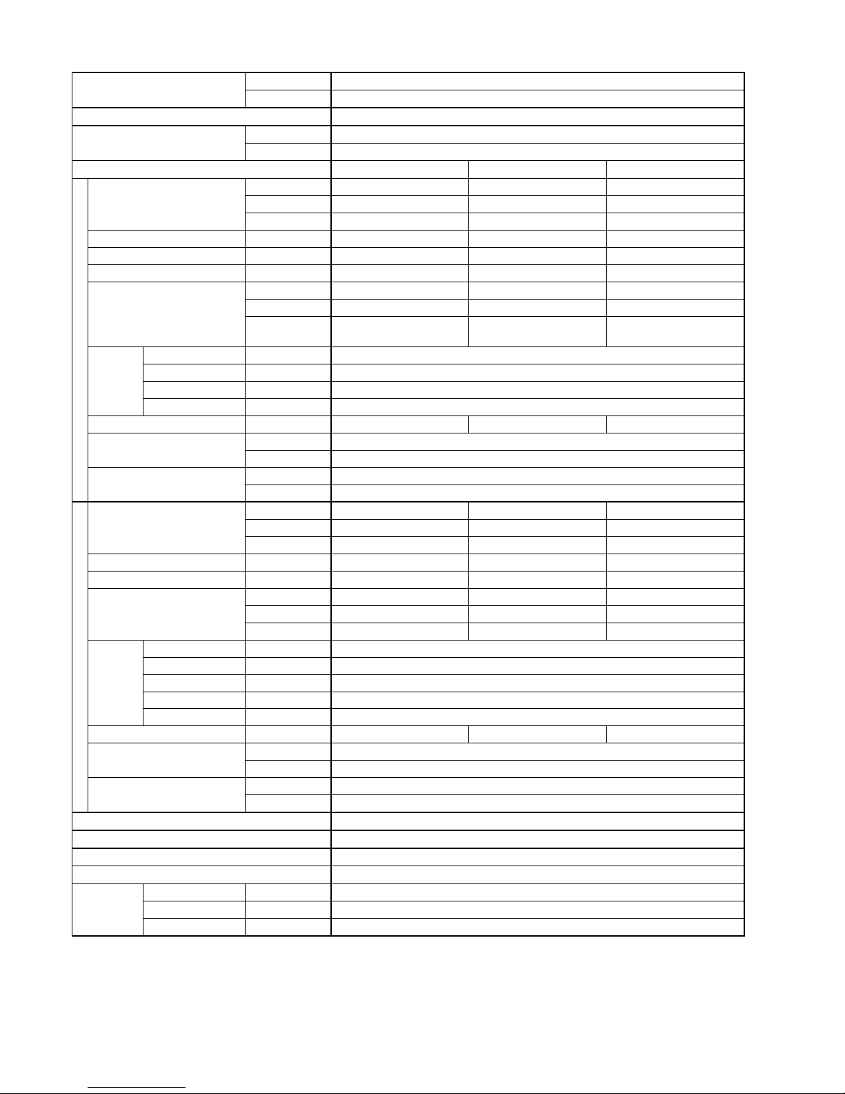
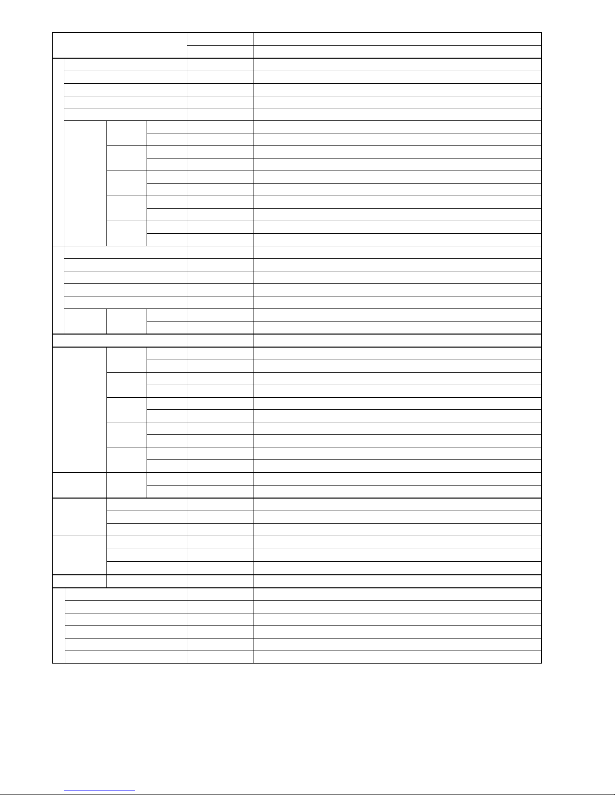
3. Specification
Model
Indoor CS-HZ9RKE CS-HZ9RKE-4 CS-AZ9RKE
Outdoor CU-HZ9RKE CU-HZ9RKE-4 CU-AZ9RKE
Performance Test Condition EUROVENT
Power Supply
Phase, Hz Single, 50
V 230
Min. Mid. Max.
Cooling
Capacity
kW 0.85 2.50 3.00
BTU/h 2900 8530 10200
kcal/h 730 2150 2580
Running Current A – 2.20 –
Input Power W 170 455 670
Annual Consumption kWh – 228 –
EER
W/W 5.00 5.49 4.48
BTU/hW 17.06 18.75 15.22
kcal/hW 4.29 4.73 3.85
ErP
Pdesign kW 2.5
SEER (W/W) 7.8
Annual Consumption kWh 112
Class A++
Power Factor % – 90 –
Indoor Noise (H / L / QLo)
dB-A 39 / 25 / 20
Power Level dB 55 / - / -
Outdoor Noise (H / L / QLo)
dB-A 46 / - / 43
Power Level dB 61 / - / -
Heating
Capacity
kW 0.85 3.20 6.65
BTU/h 2900 10900 22700
kcal/h 730 2750 5720
Running Current A – 2.70 –
Input Power W 165 5.70 1.76k
COP
W/W 5.15 5.61 3.78
BTU/hW 17.58 19.12 12.90
kcal/hW 4.42 4.82 3.25
ErP
Pdesign kW 3.0
Tbivalent °C -10
SCOP (W/W) 5.2
Annual Consumption kWh 808
Class A+++
Power Factor % – 92 –
Indoor Noise (H / L / QLo)
dB-A 44 / 24 / 18
Power Level dB 60 / - / -
Outdoor Noise (H / L / QLo)
dB-A 47 / - / 44
Power Level dB 62 / - / -
Low Temp. : Capacity (kW) / I.Power (W) / COP 4.82 / 1.56k / 3.09
Extr Low Temp. : Capacity (kW) / I.Power (W) / COP 4.10 / 1.57k / 2.61
Max Current (A) / Max Input Power (W) 7.7 / 1.76k
Starting Current (A) 2.70
Compressor
Type Hermetic Motor (Rotary)
Motor Type Brushless (4 poles)
Output Power W 900
11
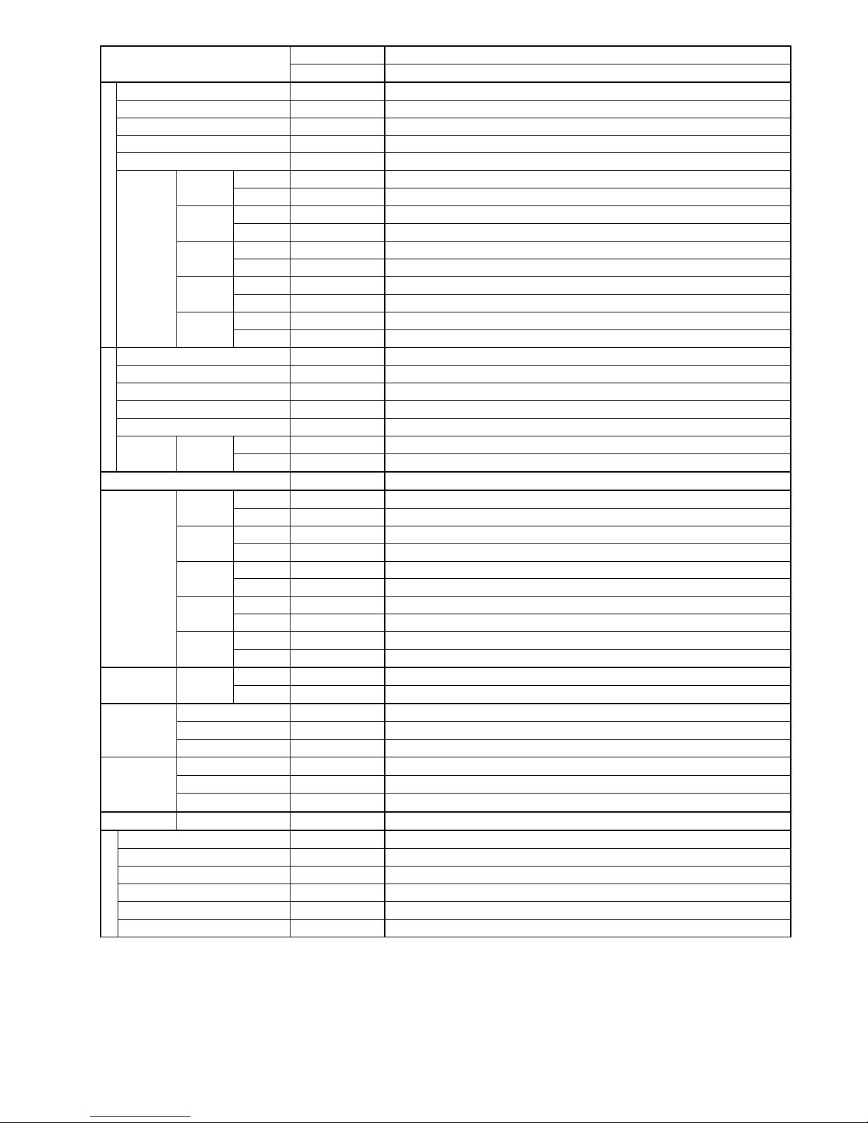
Model
Indoor CS-HZ9RKE CS-HZ9RKE-4 CS-AZ9RKE
Outdoor CU-HZ9RKE CU-HZ9RKE-4 CU-AZ9RKE
Indoor Fan
Type Cross-Flow Fan
Material ASG33
Motor Type DC / Transistor (8-poles)
Input Power W 44.9
Output Power W 40
Speed
QLo
Cool rpm 570
Heat rpm 630
Lo
Cool rpm 670
Heat rpm 720
Me
Cool rpm 880
Heat rpm 990
Hi
Cool rpm 1090
Heat rpm 1270
SHi
Cool rpm 1150
Heat rpm 1340
Outdoor Fan
Type Propeller Fan
Material PP
Motor Type DC Motor (8-poles)
Input Power W –
Output Power W 40
Speed Hi
Cool rpm 850
Heat rpm 850
Moisture Removal L/h (Pt/h) 1.5 (3.2)
Indoor Airflow
QLo
Cool m
3
/min (ft3/min) 6.01 (212)
Heat m3/min (ft3/min) 6.78 (239)
Lo
Cool m
3
/min (ft3/min) 7.29 (257)
Heat m3/min (ft3/min) 7.93 (280)
Me
Cool m
3
/min (ft3/min) 9.99 (353)
Heat m3/min (ft3/min) 11.41 (403)
Hi
Cool m
3
/min (ft3/min) 12.30 (435)
Heat m3/min (ft3/min) 15.00 (530)
SHi
Cool m
3
/min (ft3/min) 13.46 (475)
Heat m3/min (ft3/min) 15.91 (562)
Outdoor
Airflow
Hi
Cool m
3
/min (ft3/min) 33.10 (1170)
Heat m3/min (ft3/min) 34.00 (1200)
Refrigeration
Cycle
Control Device Expansion Valve
Refrigerant Oil cm3 FW50S (450)
Refrigerant Type g (oz) R32, 1.12k (39.5)
Dimension
Height(I/D / O/D) mm (inch) 295 (11-5/8) / 622 (24-1/2)
Width (I/D / O/D) mm (inch) 870 (34-9/32) / 824 (32-15/32)
Depth (I/D / O/D) mm (inch) 255 (10-1/16) / 299 (11-25/32)
Weight Net (I/D / O/D) kg (lb) 10 (22) / 38 (84)
Piping
Pipe Diameter (Liquid / Gas) mm (inch) 6.35 (1/4) / 9.52 (3/8)
Standard length m (ft) 5.0 (16.4)
Length range (min – max) m (ft) 3 (9.8) ~ 20 (65.6)
I/D & O/D Height different m (ft) 10.0 (32.8)
Additional Gas Amount g/m (oz/ft) 20 (0.2)
Length for Additional Gas m (ft) 7.5 (24.6)
12
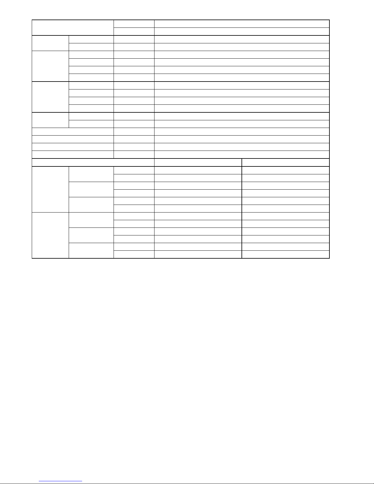
Model
Indoor CS-HZ9RKE CS-HZ9RKE-4 CS-AZ9RKE
Outdoor CU-HZ9RKE CU-HZ9RKE-4 CU-AZ9RKE
Drain Hose
Inner Diameter mm 16
Length mm 650
Indoor Heat
Exchanger
Fin Material Aluminium (Pre Coat)
Fin Type Slit Fin
Row × Stage × FPI 2 × 17 × 21
Size (W × H × L) mm 636.5 × 357 × 25.4
Outdoor Heat
Exchanger
Fin Material Aluminium
Fin Type Corrugate Fin
Row × Stage × FPI 2 × 28 × 19
Size (W × H × L) mm 36.4 × 588 × 856.3:827.7
Air Filter
Material Polypropelene
Type One-touch
Power Supply Indoor / Outdoor
Power Supply Cord A Nil
Thermostat Electronic Control
Protection Device Electronic Control
Dry Bulb Wet Bulb
Indoor
Operation
Range
Cooling
Maximum °C 32 23
Minimum °C 16 11
Heating
Maximum °C 30 –
Minimum °C 16 –
+8/10°C
HEAT
Maximum °C 10 –
Minimum °C 8 –
Outdoor
Operation
Range
Cooling
Maximum °C 43 26
Minimum °C 16 11
Heating
Maximum °C 24 18
Minimum °C -20 –
+8/10°C
HEAT
Maximum °C – –
Minimum °C -20 –
1. Cooling capacities are based on indoor temperature of 27°C Dry Bulb (80.6°F Dry Bulb), 19.0°C Wet Bulb (66.2°F Wet Bulb) and outdoor air
temperature of 35°C Dry Bulb (95°F Dry Bulb), 24°C Wet Bulb (75.2°F Wet Bulb)
2. Heating capacities are based on indoor temperature of 20°C Dry Bulb (68°F Dry Bulb) and outdoor air temperature of 7°C Dry Bulb (44.6°F
Dry Bulb), 6°C Wet Bulb (42.8°F Wet Bulb)
3. Heating low temperature capacity, Input Power and COP measured at 230 V, indoor temperature 20°C, outdoor 2/1°C.
4. Heating extreme low temperature capacity, Input Power and COP measured at 230 V, indoor temperature 20°C, outdoor -7/-8°C.
5. Specifications are subjected to change without prior notice for further improvement.
6. Maximum heating capacity shown are the values based on powerful operation.
7. If the EUROVENT Certified models can be operated under the “extra-low” temperature condition, -7°C DB and -8°C WB temperature with
rated voltage 230V shall be used.
8. The annual consumption is calculated by multiplying the input power by an average of 500 hours per year in cooling mode.
9. SEER and SCOP classification is at 230V only in accordance with EN-14825. For heating, SCOP indicates the value of only Average heating
season. Other fiche data indicates in an attached sheet.
13
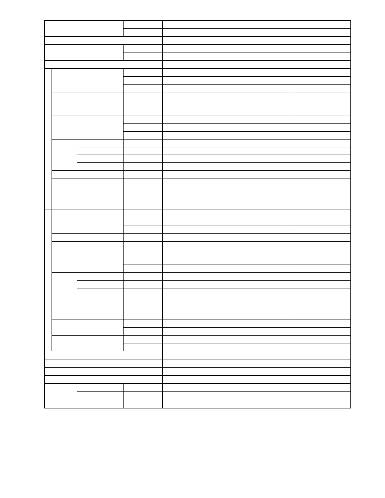
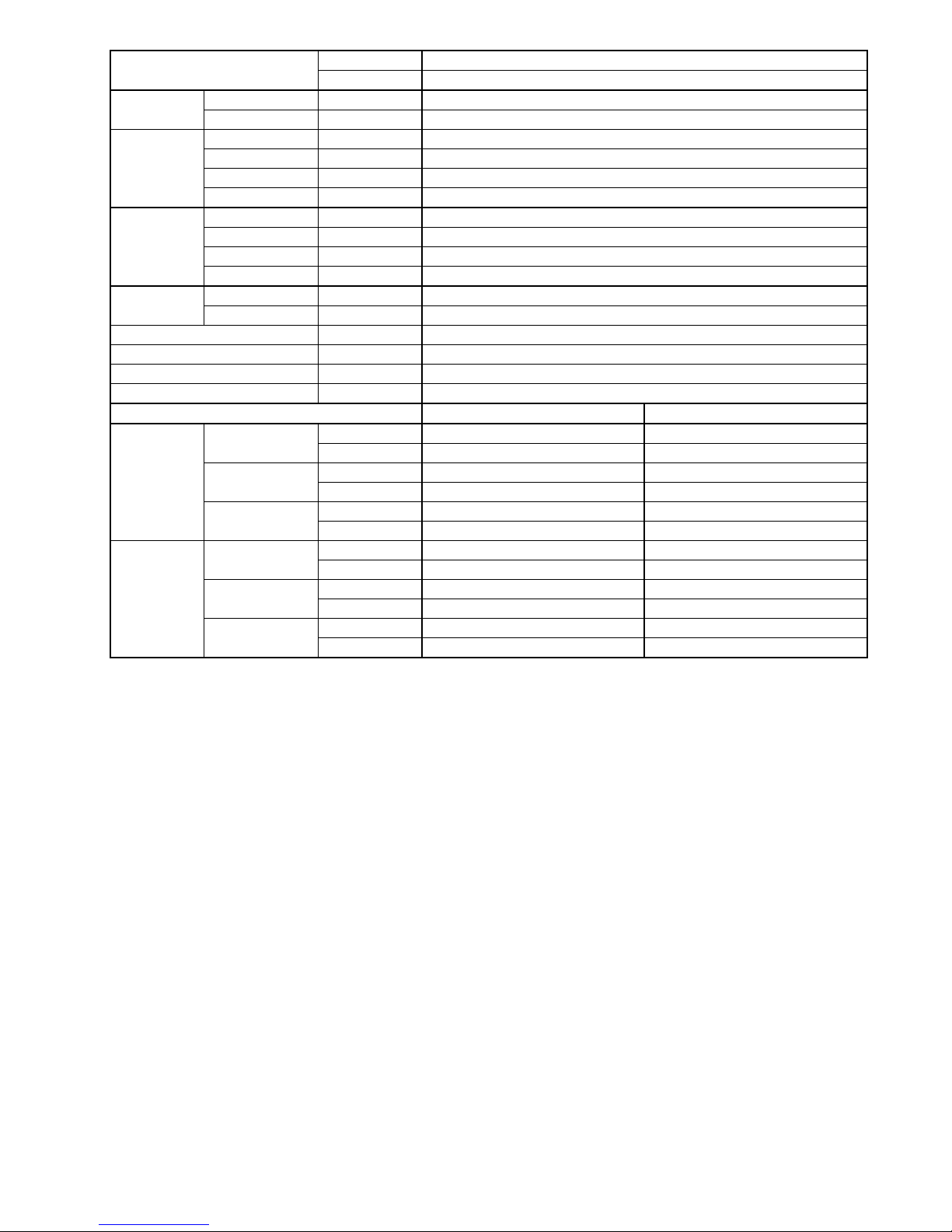
Model
Indoor CS-HZ12RKE
Outdoor CU-HZ12RKE
Performance Test Condition EUROVENT
Power Supply
Phase, Hz Single, 50
V 230
Min. Mid. Max.
Cooling
Capacity
kW 0.85 3.50 4.00
BTU/h 2900 11900 13600
kcal/h 730 3010 3440
Running Current A – 3.80 –
Input Power W 170 830 990
Annual Consumption kWh – 415 –
EER
W/W 5.00 4.22 4.04
BTU/hW 17.06 14.34 13.74
kcal/hW 4.29 3.63 3.47
ErP
Pdesign kW 3.5
SEER (W/W) 7.6
Annual Consumption kWh 161
Class A++
Power Factor % – 95 –
Indoor Noise (H / L / QLo)
dB-A 42 / 28 / 20
Power Level dB 58 / - / -
Outdoor Noise (H / L / QLo)
dB-A 48 / - / 45
Power Level dB 63 / - / -
Heating
Capacity
kW 0.85 4.20 7.75
BTU/h 2900 14300 26400
kcal/h 730 3610 6670
Running Current A – 3.95 –
Input Power W 165 840 2.27k
COP
W/W 5.15 5.00 3.41
BTU/hW 17.58 17.02 11.63
kcal/hW 4.42 4.30 2.94
ErP
Pdesign kW 3.8
Tbivalent °C -10
SCOP (W/W) 5.1
Annual Consumption kWh 1043
Class A+++
Power Factor % – 92 –
Indoor Noise (H / L / QLo)
dB-A 45 / 25 / 18
Power Level dB 61 / - / -
Outdoor Noise (H / L / QLo)
dB-A 50 / - / 47
Power Level dB 65 / - / -
Low Temp. : Capacity (kW) / I.Power (W) / COP 5.62 / 2.01k / 2.80
Extr Low Temp. : Capacity (kW) / I.Power (W) / COP 4.70 / 1.93k / 2.44
Max Current (A) / Max Input Power (W) 9.9 / 2.27k
Starting Current (A) 3.95
Compressor
Type Hermetic Motor (Rotary)
Motor Type Brushless (4-poles)
Output Power W 900
14
Model
Indoor CS-HZ12RKE
Outdoor CU-HZ12RKE
Indoor Fan
Type Cross-flow Fan
Material ASG33
Motor Type DC / Transistor (8-poles)
Input Power W 44.9
Output Power W 40
Speed
QLo
Cool rpm 570
Heat rpm 630
Lo
Cool rpm 720
Heat rpm 740
Me
Cool rpm 920
Heat rpm 1020
Hi
Cool rpm 1130
Heat rpm 1300
SHi
Cool rpm 1200
Heat rpm 1370
Outdoor Fan
Type Propeller Fan
Material PP
Motor Type DC Motor (8-poles)
Input Power W –
Output Power W 40
Speed Hi
Cool rpm 860
Heat rpm 890
Moisture Removal L/h (Pt/h) 2.0 (4.2)
Indoor Airflow
QLo
Cool m
3
/min (ft3/min) 6.01 (212)
Heat m3/min (ft3/min) 6.78 (239)
Lo
Cool m
3
/min (ft3/min) 7.93 (280)
Heat m3/min (ft3/min) 8.19 (289)
Me
Cool m
3
/min (ft3/min) 10.51 (371)
Heat m3/min (ft3/min) 11.79 (416)
Hi
Cool m
3
/min (ft3/min) 13.20 (465)
Heat m3/min (ft3/min) 15.40 (545)
SHi
Cool m
3
/min (ft3/min) 14.11 (498)
Heat m3/min (ft3/min) 16.29 (575)
Outdoor
Airflow
Hi
Cool m
3
/min (ft3/min) 34.40 (1215)
Heat m3/min (ft3/min) 35.60 (1255)
Refrigeration
Cycle
Control Device Expansion Valve
Refrigerant Oil cm3 FW50S (450)
Refrigerant Type g (oz) R32, 1.12k (39.5)
Dimension
Height(I/D / O/D) mm (inch) 295 (11-5/8) / 622 (24-1/2)
Width (I/D / O/D) mm (inch) 870 (34-9/32) / 824 (32-15/32)
Depth (I/D / O/D) mm (inch) 255 (10-1/16) / 299 (11-25/32)
Weight Net (I/D / O/D) kg (lb) 10 (22) / 38 (84)
Piping
Pipe Diameter (Liquid / Gas) mm (inch) 6.35 (1/4) / 9.52 (3/8)
Standard length m (ft) 5.0 (16.4)
Length range (min – max) m (ft) 3 (9.8) ~ 20 (65.6)
I/D & O/D Height different m (ft) 10.0 (32.8)
Additional Gas Amount g/m (oz/ft) 20 (0.2)
Length for Additional Gas m (ft) 7.5 (24.6)
15
Model
Indoor CS-HZ12RKE
Outdoor CU-HZ12RKE
Drain Hose
Inner Diameter mm 16
Length mm 650
Indoor Heat
Exchanger
Fin Material Aluminium (Pre Coat)
Fin Type Slit Fin
Row × Stage × FPI 2 × 17 × 21
Size (W × H × L) mm 636.5 × 357 × 25.4
Outdoor Heat
Exchanger
Fin Material Aluminium
Fin Type Corrugate Fin
Row × Stage × FPI 2 × 28 × 19
Size (W × H × L) mm 36.4 × 588 × 856.3:827.7
Air Filter
Material Polypropelene
Type One-touch
Power Supply Indoor / Outdoor
Power Supply Cord A Nil
Thermostat Electronic Control
Protection Device Electronic Control
Dry Bulb Wet Bulb
Indoor
Operation
Range
Cooling
Maximum °C 32 23
Minimum °C 16 11
Heating
Maximum °C 30 –
Minimum °C 16 –
+8/10°C
HEAT
Maximum °C 10 –
Minimum °C 8 –
Outdoor
Operation
Range
Cooling
Maximum °C 43 26
Minimum °C 16 11
Heating
Maximum °C 24 18
Minimum °C -20 –
+8/10°C
HEAT
Maximum °C – –
Minimum °C -20 –
1. Cooling capacities are based on indoor temperature of 27°C Dry Bulb (80.6°F Dry Bulb), 19.0°C Wet Bulb (66.2°F Wet Bulb) and outdoor air
temperature of 35°C Dry Bulb (95°F Dry Bulb), 24°C Wet Bulb (75.2°F Wet Bulb)
2. Heating capacities are based on indoor temperature of 20°C Dry Bulb (68°F Dry Bulb) and outdoor air temperature of 7°C Dry Bulb (44.6°F
Dry Bulb), 6°C Wet Bulb (42.8°F Wet Bulb)
3. Heating low temperature capacity, Input Power and COP measured at 230 V, indoor temperature 20°C, outdoor 2/1°C.
4. Heating extreme low temperature capacity, Input Power and COP measured at 230 V, indoor temperature 20°C, outdoor -7/-8°C.
5. Specifications are subjected to change without prior notice for further improvement.
6. Maximum heating capacity shown are the values based on powerful operation.
7. If the EUROVENT Certified models can be operated under the “extra-low” temperature condition, -7°C DB and -8°C WB temperature with
rated voltage 230V shall be used.
8. The annual consumption is calculated by multiplying the input power by an average of 500 hours per year in cooling mode.
9. SEER and SCOP classification is at 230V only in accordance with EN-14825. For heating, SCOP indicates the value of only Average heating
season. Other fiche data indicates in an attached sheet.

16
4. Features
Inverter Technology
o Wider output power range
o Energy saving
o More precise temperature control
Long Installation Piping
o Long piping up to 20 meters during single split connection only
Easy to use remote control
Quality Improvement
o Random auto restart after power failure for safety restart operation
o Gas leakage protection
o Prevent compressor reverse cycle
o Inner protector to protect Compressor
o Noise prevention during soft dry operation
Operation Improvement
o Quiet mode to reduce the indoor unit operating sound
o Powerful mode to reach the desired room temperature quickly
o 24-hour timer setting
o +8/10°C HEAT operation is designed to provide heating at low temperature settings. It is used in houses
unoccupied during winter, for the purpose of protecting equipment or housing appliances which may be
destroyed by extreme cold weather
Serviceability Improvement
o Breakdown Self Diagnosis function
17
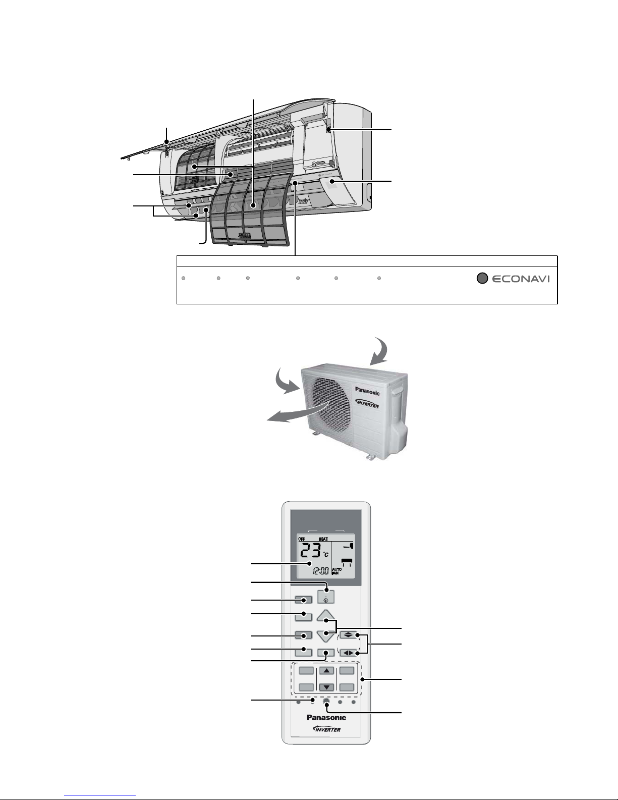
5. Location of Controls and Components
5.1 Indoor Unit
Front panel
Air Filters
Horizontal airflow direction louver
• Do not adjus t by hand.
Auto OFF/ON button
Sunli ght Sensor an d Remote C ontrol Receiver
(Maximum distances: 8m )
• Use when remote control is misplaced or
a malfunct i on occurs.
Aluminium fi n
V
ertical airflow
d
irection louver
• Do not adjust
by hand.
Indicator
TIMER
+8/10°C HEAT
DEICE POWERFUL QUIETPOWER
)egnarO()eulB()neerG()neerG( (Orange)(Orange) (Green)
5.2 Outdoor Unit
Air inlet (rear)
A
ir outlet
Air inlet (side)
5.3 Remote Control
CLOCK
MODE
AIR CONDIT IONER
OFF/ON
SET CHECK RESET
AC
RC
ON
OFF
SET
CANCEL
123
TIMER
ECONAVI
+8/10°C
HEAT
MODE
TEMP
FAN SPEED
AIR SWING
POWERFUL/QUIET
+8/10°C
HEAT
Remote control
display
ECONAVI opera tion
Operation m od e
OFF/ON
Temperature settin
g
Timer setting
+8/10°C HEAT operation
Powerful/Quiet operation
Check
Fan Speed selection
Clock setting
Airflow direction
selection
18
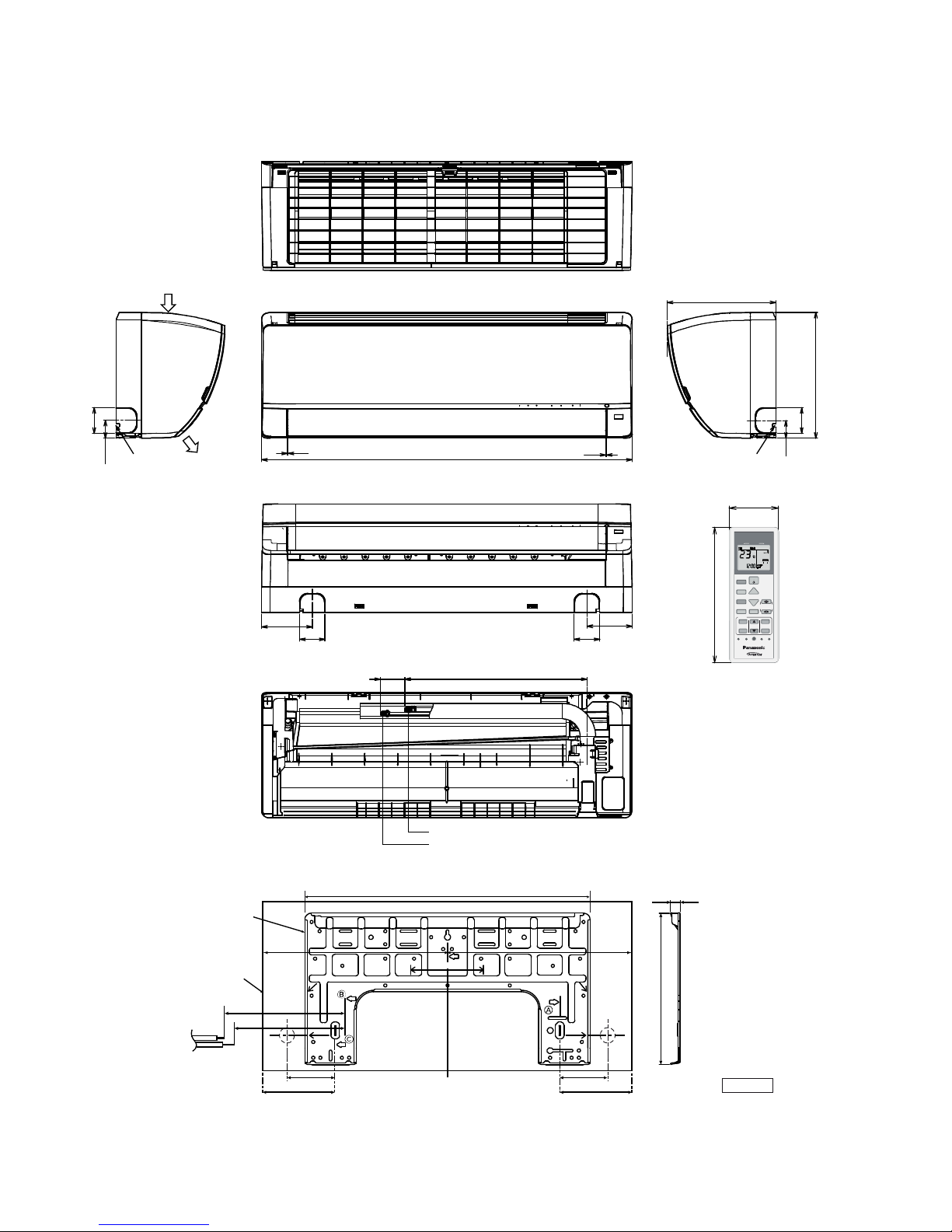
6. Dimensions
6.1 Indoor Unit
CLOCK
MODE
AIR CONDITIONER
OFF/ON
SET CHECK RESET
AC
RC
ON
OFF
SET
CANCEL
123
TIMER
ECONAVI
+8/10°C
HEAT
MODE
TEMP
FAN SPEED
AIR SWING
POWERF UL /QUIET
+8/10°C
HEAT
Liquid side
Gas side
60
119.1
60
105.8
1-2 1-2
Left ping
hole
<Remote Control Transmitter>
Relative position between the indoor unit and the installation plate <Front View>
<Top View>
<Side View><Side View>
<Front View>
<Bottom View>
<Rear View>
Right ping hole
Air intake
direction
Air outlet
direction
16.4
264.1
Unit : mm
870
590(41-61)
255
295
60
41.5
60
41.5
Right
piping
hole
Left
piping
hole
497.2
Indoor unit
external
dimensions
line
Installation
plate
128
435
127
88
128
435
DISTANCE
TO PIPE
HOLE
CENTER
128 mm
DISTANCETO
PIPE HOLE
CENTER 128 mm
PIPE HOLE CEN TER
PIPE HOLE
CENTER
128
241.5241.5
59
160
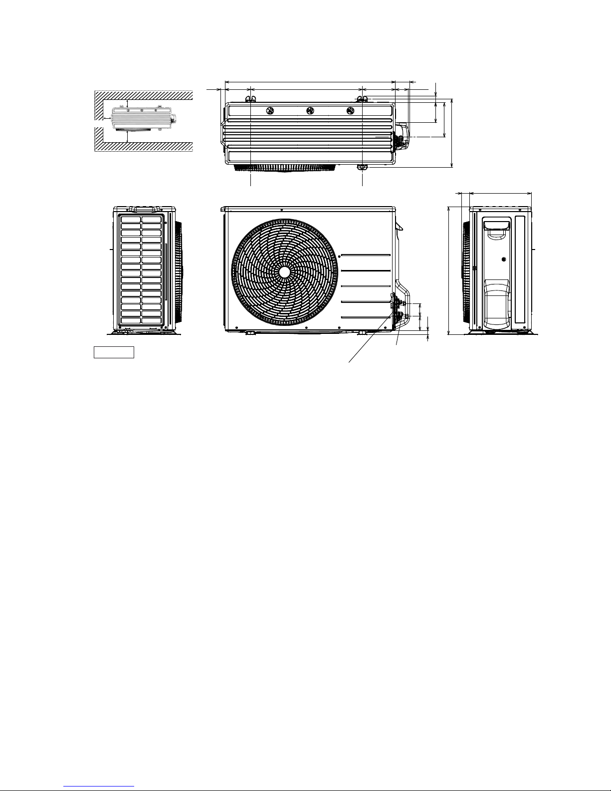
19
6.2 Outdoor Unit
<Top View>
<Front View><Side View>
<Side View>
Anchor Bolt Pitch
330 x 540
Space necessary for
installation
10cm
10cm
100cm
Unit : mm
3-way valve at Gas side
(Low Pressure)
2-way valve at Liquid si de
(High Pressure)
22 (124) (53.4)
330
622
167
97
69
(23)
61
32
540 160
824 68.5
37 299
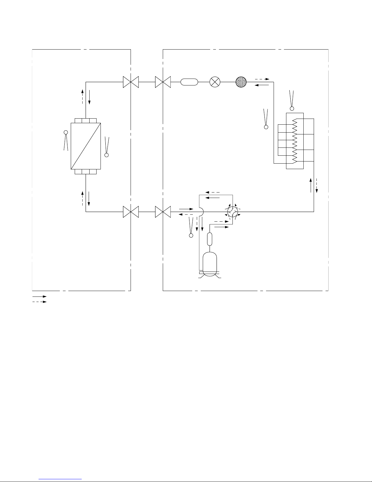
20
7. Refrigeration Cycle Diagram
INDOOR OUTDOOR
INTAKE
TEMP.
SENSOR
PIPE
TEMP.
SENSOR
TAN K
TEMP.
SENSOR
INTAKE
TEMP.
SENSOR
PIPE
TEMP.
SENSOR
LIQUID
SIDE
2-WAY
VALV E
3-WAY
VALV E
GAS
SIDE
COOLING
HEAT EXCHANGER
(EVAPORATOR)
HEAT EXCHANGER
(CONDENSER)
HEATING
COMPRESSOR
4-WAY VALVE
STRAINER
EXPANSION
VALV E
MUFFLER
MUFFLER
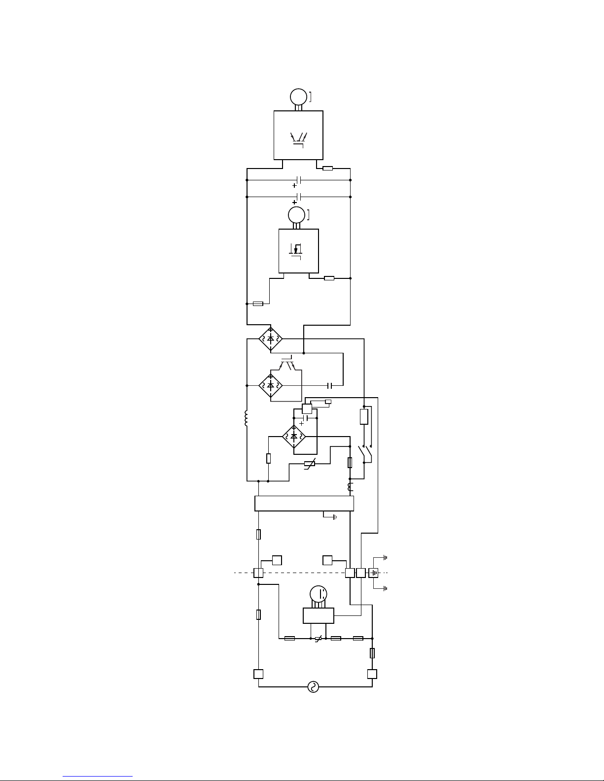
21
8. Block Diagram
8.1 Indoor Power Supply Connection
SINGLE
PHASE
POWER
SUPPLY
1Ø 230V
50Hz
SC
TEMPERATURE
FUSE
M
1
FUSE 103
FUSE 501
FUSE 500
3
1
(INDOOR UNIT) (OUTDOOR UNIT)
u
FUSE 104
PTC
2
NOISE FILTER
CT101
REACTOR
NTC
TH1
RY-PWR
RY-AC
PTC1
C103
L
N
IC19
MS
3~
MS
3~
FUSE 101
SC
4-WAYS
VALV E
u
FUSE 301
TEMPERATURE
FUSE
L
N
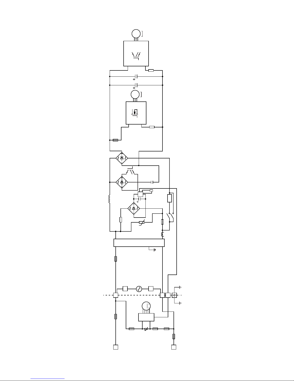
22
8.2 Outdoor Power Supply Connection
SINGLE
PHASE
POWER
SUPPLY
1Ø 230V
50Hz
SC
TEMPERATURE
FUSE
M
1
FUSE 103
FUSE 501
3
1
(INDOOR UNIT) (OUTDOO R UNIT)
u
FUSE 104
PTC
2
NOISE FILTER
CT101
REACTOR
NTC
TH1
RY-PWR
RY-AC
PTC1
C103
IC19
MS
3~
MS
3~
FUSE 101
SC
4-WAYS
VALV E
u
FUSE 301
TEMPERATURE
FUSE
L
N
FUSE 500
L
N
23
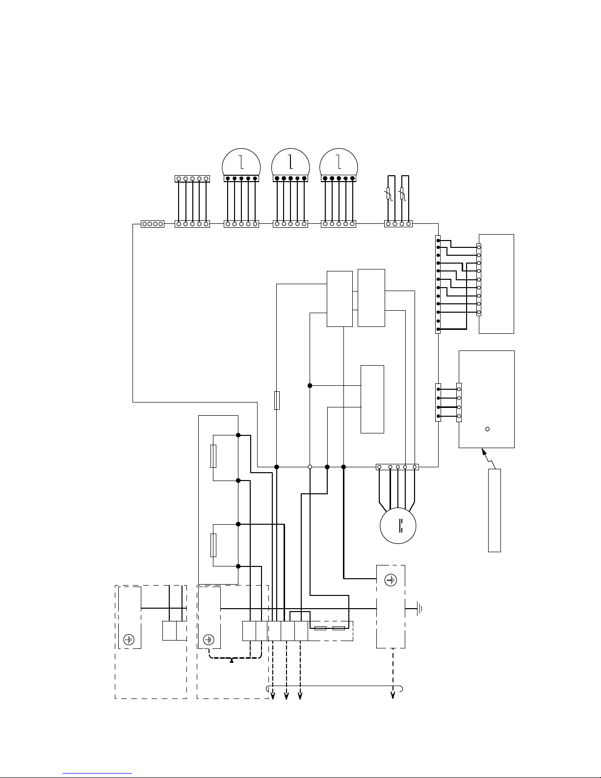
9. Wiring Connection Diagram
9.1 Indoor Unit
t
t
REMOTE CONTROLLER
ELECTRONIC CONTROLLER
(RECEIVER)
LIGHT SENSOR
CN–DISP (YLW)
COMMUNICATION
CIRCUIT
GROUNDING
TERMINAL
Y/G
EVAPORATOR
CN–STM1
(WHT)
CN–STM2
(YLW)
CN–RMT
(WHT)
4
1
CN–CNT
(WHT)
1
BR
R
O
Y
P
BR
R
O
Y
P
5
1
5
GR
W
BR
G
Y
5
1
5
1
1
5
4
1
1
M
M
5
ELECTRONIC CONTROLLER
(DISPLAY)
CN–DISP (WHT)
1
9
4
1
1
4
1346 10
12
CN−TH
(RED)
WWWW
WWWWW WW
WW
PIPING TEMP. SENSOR 1
(THERMISTOR)
SUCTION TEMP. SENSOR
(THERMISTOR)
UP DOWN
LOUVER MOTOR
(OUTER)
LEFT RIGHT
LOUVER MOTOR
CN–STM4
(BLU)
BR
R
O
Y
P
1
5
1
M
5
UP DOWN
LOUVER MOTOR
(INNER)
FAN MOTOR
M
1
7
4
CN−FM (WHT)
CN−RCV
(YLW)
CN−RCV
(WHT)
B
BLYW
R
REMARKS:B
:
BLUE P
:
PINK
BR
:
BROWN O
:
ORANGE
BL
:
BLACK Y
:
YELLOW
W
:
WHITE G
:
GREEN
R
:
RED
GR
:
GRAY
Y/G
:
YELLOW/GREEN
ELECTRONIC CONTROLLER
(MAIN)
ELECTRONIC CONTROLLER (FUSE)
Y/G
1
W
W
R
G
2
3
L
N
BRGR
ACN501
(
GRAY
)
ACN502
(
WHITE
)
ACL501
(
BROWN
)
ACL502
(
BLACK
)
BL
BL
AC303
(
WHT
)
AC306
(
BLK
)
AC304
(
RED
)
G301
(
GRN
)
FUSE301
T3.15A L250V
20A 250V
FUSE500
20A 250V
FUSE501
NOISE FILTER
CIRCUIT
RECTIFICATION
CIRCUIT
TEMP. FUSE
102°C (3A)
TEMP. FUSE
102°C (3A)
TERMINAL
BOARD
GROUNDING
TERMINAL
TO
OUTDOOR
UNIT
SINGLE PHASE
POWER SUPPLY
1
Ø
230V 50Hz
L
N
TERMINAL
BOARD
FOR OUTDOOR POWER SUPPLY CONNECTION
FOR INDOOR POWER SUPPLY CONNECTION
GROUNDING
TERMINAL
POWER
SUPPLY
NOT
CONNETED
24
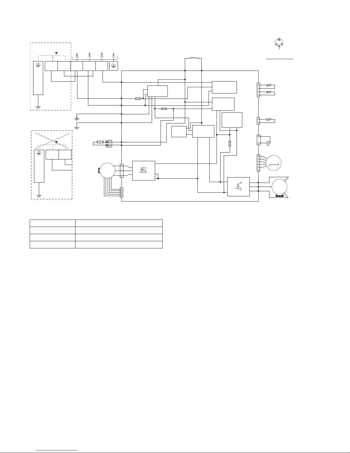
9.2 Outdoor Unit
REMARKS;
BLACK; (BLK) BLUE; (BLU)
WHITE; (WHT) RED; (RED)
YELLOW; (YLW) GRAY; (GRY)
GREEN; (GRN) BROWN; (BRW)
ORANGE;
(ORG)
YELLOW/GREEN; (YLW/GRN)
MS
3
~
MS
3
~
FAN
MO TOR
BASE PAN
HEATER
BLU
1
1
10
14
16
IC19
3
W
U
V
5
5
BLU
3
1
GRN
GRN
WHT
WHT
BLK
YLW/GRN
BLK
RED DATA (RED)
AC-WH T (WHT)
FG1 (GRN)
FG2 (GRN)
AC-BLK
(BLK )
FUSE 103
(20A 250V)
RAT2
(G RY)
RAT1
(G RY)
REAC TOR
GRY GRY
NOISE FILTER
CIRCUIT
PFC
CIRCUIT
RECTIFICATION
CIRCUIT
RECTIFICATION
CIRCUIT
COMMUNICATI O N
CIRCUIT
OUTD OOR AIR TE MP.
SEN SOR (T HERMIS T OR)
YELLOW (YLW)
BLUE(BLU) RED (RED)
(TRADEMARK)
COMPRESSOR TERMINAL
THE PARENTHESIZED LETTERS IS
INDICATED ON TERMINAL COVER.
PIPING TEMP.
SENSOR (THERMIS TOR)
CN-TH1
(WHT)
CN-TANK
(WHT)
CN-HOT
(WHT)
CN-STM
(WHT)
U(RED)
V(BLU)
W(YLW)
RED
BLU
YLW
COMPRESSOR
M
COMPRESSOR TEM P.
SENS OR (THERMIS T OR)
ELE CTRO-MA GNETIC
COIL (4-WAY VALVE)
ELECTRO-MAGNETIC COIL
(E XPA NS ION VALV E)
1
1
1
1
P
FUSE 101
T3.15A L2 50V
N
Q1
U
V
W
6
3
3
t
°
t
°
t
°
4
SWITCHING
POWER SUPPLY
CIRCUIT
FUSE 104
T3.15A L250V
ELECTRONIC CONTROLLER
TERMINAL
BOARD
(BLK ) (WHT ) (RED)
TO INDOOR UNIT
SINGLE PHASE
POWER SUPPLY
SINGLE PHASE
POWER SUPPLY
FOR OUTDOOR POWER
SUPPLY CONNECTION
FOR INDOOR POWER
SUPPLY CONNECTION
1
(BLK)2(WHT)
L
GROUNDING TERMINAL
N
3
(RED)
HT2 (BLU)
ACN2 (BLU)
CN-MTR2
(WHT )
CN-MTR1
(WHT)
YLW/GRN
BLK
L
GROUNDING TERMINAL
N
Resistance of Compressor Windings
CONNECTION 9RD132XAB21
U - V 1.897Ω
U - W 1.907Ω
V - W 1.882Ω
Winding resistance at 20°C.
25
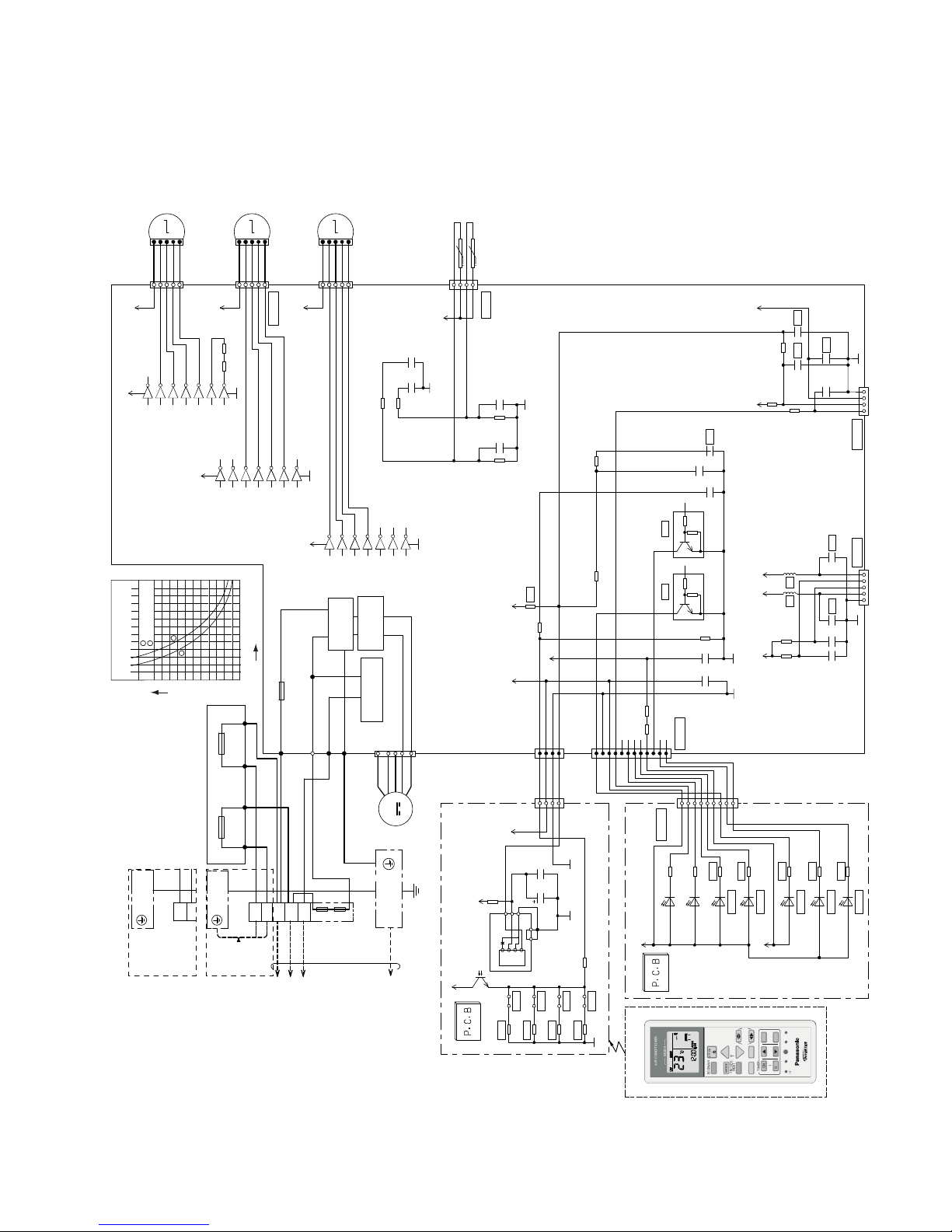
10. Electronic Circuit Diagram
10.1 Indoor Unit
CLOCK
MODE
AIR CONDITIONER
OFF/ON
SET CHECK RESET
AC
RC
ON
OFF
SET
CANCEL
123
TIMER
ECONAVI
+8/10°C
HEAT
MODE
TEMP
FAN SPEED
AIR SWING
POWERFUL/QUIET
+8/10°C
HEAT
COMMUNICATION
CIRCUIT
GROUNDING
TERMINAL
Y/G
EVAPORATOR
FAN MOTOR
M
1
1
123456789
101112
234
54321 1234
7
4
CN−FM (WHT)
BBLY
W
R
ELECTRONIC CONTROLLER
(MAIN)
ELECTRONIC CONTROLLER (FUSE)
Y/G
1
W
W
R
G
2
3
L
N
BRGR
ACN501
(
GRAY
)
ACN502
(
WHITE
)
ACL501
(
BROWN
)
ACL502
(
BLACK
)
BL
BL
AC303
(
WHT
)
AC306
(
BLK
)
AC304
(
RED
)
G301
(
GRN
)
FUSE301
T3.15A L250V
20A 250V
FUSE500
20A 250V
FUSE501
NOISE FILTER
CIRCUIT
RECTIFICATION
CIRCUIT
TEMP. FUSE
102°C (3A)
TEMP. FUSE
102°C (3A)
TERMINAL
BOARD
GROUNDING
TERMINAL
TO
OUTDOOR
UNIT
SINGLE PHASE
POWER SUPPLY
1
Ø
230V 50Hz
L
N
TERMINAL
BOARD
FOR OUTDOOR POWER SUPPLY CONNECTION
FOR INDOOR POWER SUPPLY CONNECTION
GROUNDING
TERMINAL
POWER
SUPPLY
NOT
CONNETED
BR
R
O
Y
P
1
M
5
UP DOWN
LOUVER MOTOR
(INNER)
CN–STM4
(BLU)
12345
16
12V
1514131211
10
1923456
7
8
GND
VCC
12V
IC06
BR
R
O
Y
P
1
M
5
LEFT RIGHT
LOUVER MOTOR
*CN–STM2
(YLW)
12345
16
12V
1514131211
10
1923456
7
8
GND
VCC IC05
12V
12V
BR
R
O
Y
P
1
M
5
UP DOWN
LOUVER MOTOR
(OUTER)
CN–STM1
(WHT)
12345
16
12V
1514131211
10
R47 R46
1923456
7
8
GND
VCC
IC03
987654321
ELECTRONIC CONTROLLER
(DISPLAY)
5V_
PCB301
*CN–DISP
(WHT)
*R303
*LED303
*LED304
*LED305
*LED306
*LED307
*R304
*R305
*R306
*R307
R301
R302
POWER
LED301
LED302
TIMER
(green)
(green)
(orange)
QUIET
(orange)
POWERFUL
(orange)
ECONAVI
(green)
+8/10°C HEAT
(blue)
Deice
12V
ELECTRONIC CONTROLLER
(RECEIVER)
CN–RCV
(WHT)
PCB201
IC201
*R210
*R214
*SEN201
*JP201
*JP202
*JP203
*JP204
*R211
*R212
*R213
5V_
GND-A
GND-A
C201 C202
R209
GND-A
c
1
432
1
2
3
54
Vout
Vcc
GND
GNDGND
e
5V_
5V_
REMOTE CONTROLLER
*CN–DISP
(YLW)
*CN–RCV
(YLW)
R91 R92
R64
R40 R39
R58
R90 R82
R37
R85
R54
C1
C52 C51
C45
C38
C14
C3
5V
12V
*Q11
*C56
*L5*L6
*C57
*R89
*Q09
e
c
b
e
c
b
5V
*C15
*C48
*C49
*C47
*CN–CNT *CN–RM T
5V 5V12V
5V 5V
123
4
*CN–TH
(RED)
C27C25
C54 C55
R61
R87
R88
R62
PIPING TEMP. SENSOR 1
(THERMISTOR)
SUCTION TEMP. SENSOR(THERMISTOR)
t
t
5V
706050
Resistan ce (kΩ)
Temperature(ºC)
Sensor (Thermistor)
Characteristics
403020
10
-10 0 10 20 30 40 50
0
Pipe Temp. Sensor
IntakeAir Temp. Sensor
112
2
26
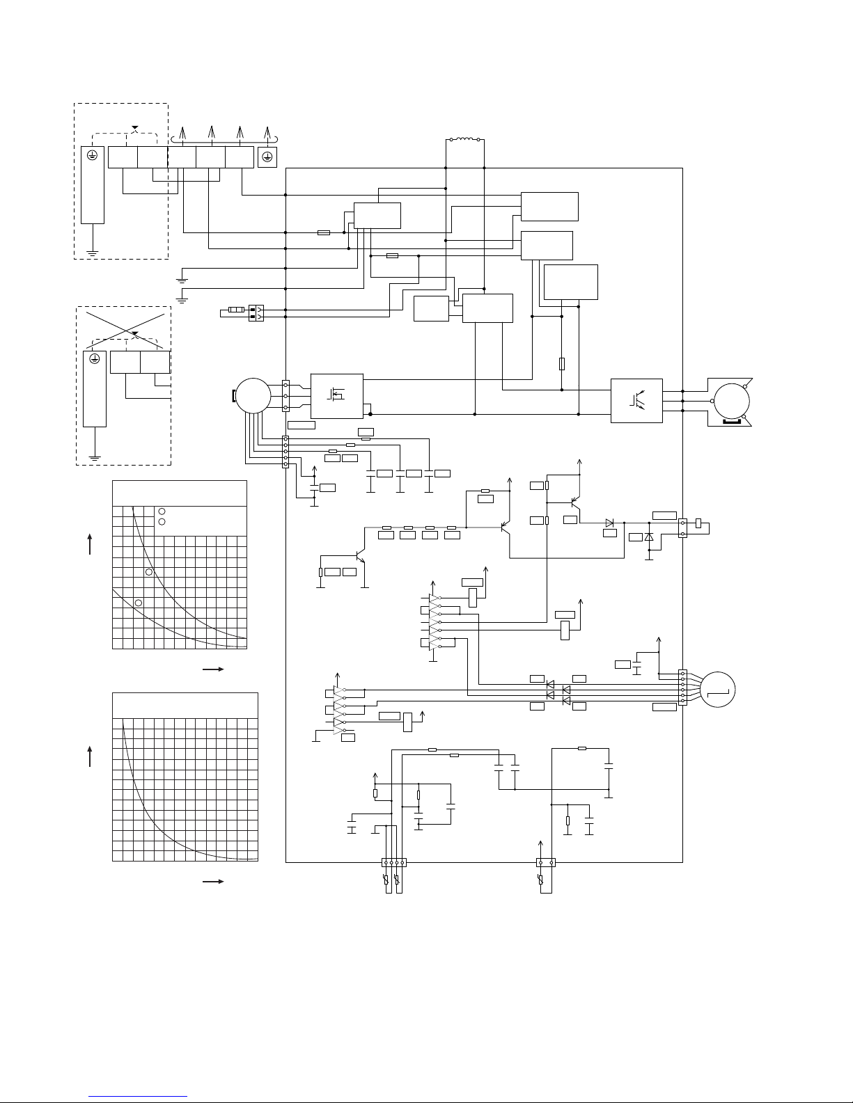
10.2 Outdoor Unit
MS
3
~
MS
3
~
FAN
MO TOR
BASE PAN
HEATER
BLU
1
1
2
3
4
10
14
16
3
W
U
V
5
5
BLU
3
1
GRN
GRN
WHT
WHT
BLK
YLW/GRN
BLK
DATA (RED)RED
AC-WHT (WHT)
FG1 (GRN)
FG2 (GRN)
FUSE 103
(20A 250V)
RAT2
(GR Y)
RAT1
(G RY)
REACTOR
GRY GRY
NOISE FI LTER
CIRCUIT
PFC
CIRCUI T
RECTIFICATION
CIRCUIT
RECTIFICATI ON
CIRCUI T
COMMUNICATION
CIRCUIT
U(RED)
V(BLU)
W(YLW)
RED
BLU
YLW
COMPRESSOR
ELE CTRO-MAGN ETIC COIL
(EXPANSION VALVE)
P
FUSE 101
T3.15A L250V
N
Q1
U
V
W
SWITCHING
POWER SUPPLY
CIRCUIT
FUSE 104
T3.15A L250V
ELECTRONIC CONTROLLER
(BLK ) (WHT ) (R ED)
TO INDOOR UNIT
SINGLE PHASE
POWER SUPPLY
SINGLE PHASE
POWER SUPPLY
FOR OUTDOOR POWER
SUPPLY CONNECTION
FOR INDOOR POWER
SUPPLY CONNECTION
1
(BLK)2(WHT)
L
GROUNDING TERMINAL
N
3
(RED)
HT2 (BLU)
ACN2 (BLU)
YLW/GRN
BLK
L
GROUNDING TERMINAL
N
*CN-MTR1
*CN-STM
*CN-HOT
IC19
5V
G2
+
G2 G2
*C178
*C186 *C188G2*C187
*R313 *R312
*R311
CN-MTR2
(WHT)
AC-BLK
(BLK)
TERMINAL
BOARD
4V
e
c
b
*D23
*D20
*R33
*R32
*Q24
*Q26
G2
15V
e
c
b
c
e
b
*R260
*RY-H T1
*RY-H T2
*RY-F M
*R284
*R211
*R278 *R277 *R 259
*C174
R47
R43
R11
R12
C88
C10
C9
R42
C64
C69
R1
C5
C63
G6G6
13V
13V
13V
IC4
VCC
GND
161
9
15
13V
14
13
12
11
10
2
3
4
5
6
7
8
G2
G2
*D73
*IC5
*D75
*D74
*D76
13V
IC5
VCC
161
6
5
4
3
2
1
31
4321
1
3
9
16
15
14
13
12
11
2
3
4
5
6
G2
13V
M
ELECTRO-MAGNETIC
COIL (4-WAY VALVE)
t
°
t°t
°
COMP TEMP. SENSOR
(50kΩ 3950)
OUTDOOR AIR TEMP. SENSOR
(15kΩ 3950)
PIPING TEMP. SENSOR1
(4.96kΩ 3800)
CN-TANKCN-TH1
5V
G2
G2G2
5V
+
G2
G2
G2
Sensor (Thermistor)
Characteristics
70
60
50
40
30
20
10
0
-10 0 10
Temperature (
o
C)
Resistance (kΩ)
20 30 40 50
1
2
1
2
Outdoor Air Sensor
Outdoor Heat Exchanger
Sensor
Compressor Temp. Sensor
(Thermistor) Characteristics
70
60
50
40
30
20
10
0
20 40 60
Temperature (
o
C)
Resistance (kΩ)
80 100 120 140
27
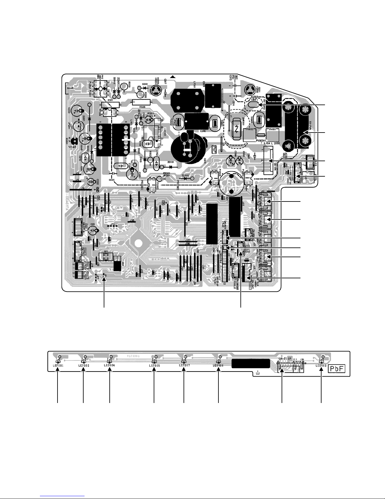
11. Printed Circuit Board
11.1 Indoor Unit
11.1.1 Main Printed Circuit Board
AC303
RY-PW
R
CN-STM1
CN-STM2
CN-STM4
CN-RCV
CN-DISP
CN-CNT
CN-TH
CN-FM
JP1 (Random Auto Restart enable/disable) CN-RMT
11.1.2 Indicator Printed Circuit Board
LED301 LED302 LED304 LED305 LED307 LED306 CN-DISP LED303
28
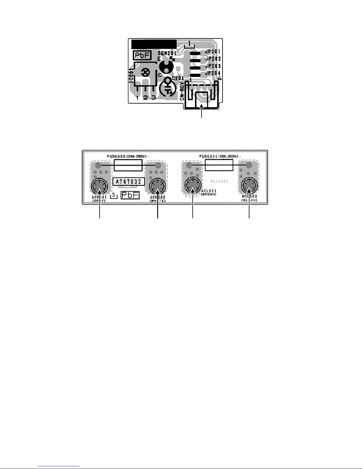
11.1.3 Receiver Printed Circuit Board
CN-RCV
11.1.4 Fuse Printed Circuit Board
ACL501ACN501 ACL502ACN502
29
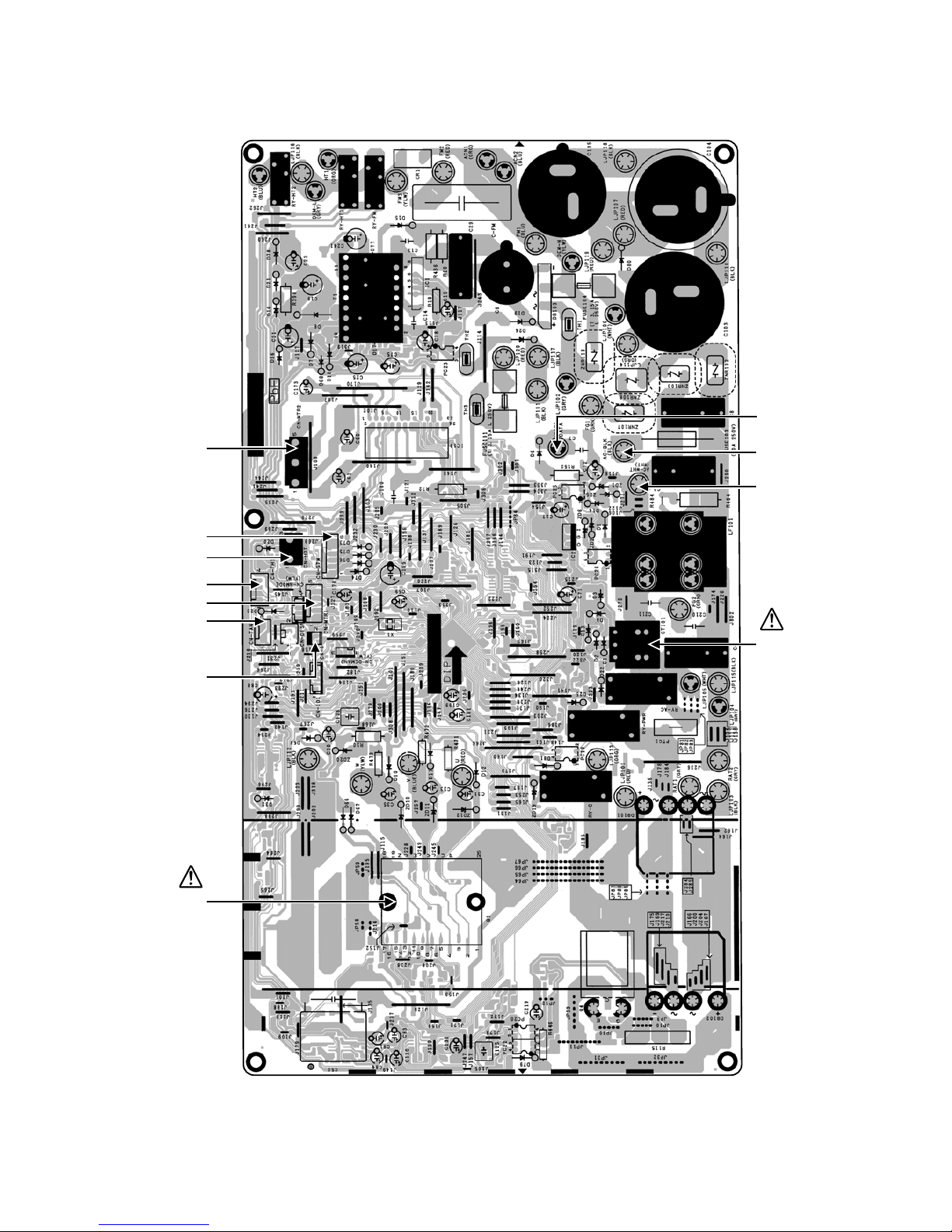
11.2 Outdoor Unit
11.2.1 Main Printed Circuit Board
CN-TANK
CN-MTR1
CN-S
CN-HOT
CN-STM
CN-MTR2
DATA
AC-BLK
AC-WHT
CN-TH1
CURRENT
TRANSFORMER
(CT)
POWER
TRANSISTOR
(IPM)
30
12. Installation Instruction
12.1 Select The Best Location
12.1.1 Indoor Unit
Do not install the unit in excessive oil fume area
such as kitchen, workshop and etc.
There should not be any heat source or steam
near the unit.
There should not be any obstacles blocking the air
circulation.
A place where air circulation in the room is good.
A place where drainage can be easily done.
A place where noise prevention is taken into
consideration.
Do not install the unit near the door way.
Ensure the spaces indicated by arrows from the
wall, ceiling, fence or other obstacles.
Recommended installation height for indoor unit
shall be at least 2.5 m.
12.1.2 Outdoor Unit
If an awning is built over the unit to prevent direct
sunlight or rain, be careful that heat radiation from
the condenser is not obstructed.
There should not be any animal or plant which
could be affected by hot air discharged.
Keep the spaces indicated by arrows from wall,
ceiling, fence or other obstacles.
Do not place any obstacles which may cause a
short circuit of the discharged air.
If piping length is over the [piping length for
additional gas], additional refrigerant should be
added as shown in the table.
Model
Horse
Powe r
(HP)
Piping size
Std.
Length
(m)
Max.
Elevation
(m)
Min.
Piping
Length
(m)
Max.
Piping
Length
(m)
Additional
Refrigerant
(g/m)
Piping
Length
for add.
gas (m)
Gas Liquid
HZ9***,
AZ9***
1.0HP
9.52mm
(3/8")
6.35mm
(1/4")
5
10 20
20
10
3207.5
HZ12*** 5.7
0
23PH5.1
Example: For HZ9***
If the unit is installed at 10 m distance, the quantity of
additional refrigerant should be 50 g …. (10-7.5) m ×
20 g/m =50 g.
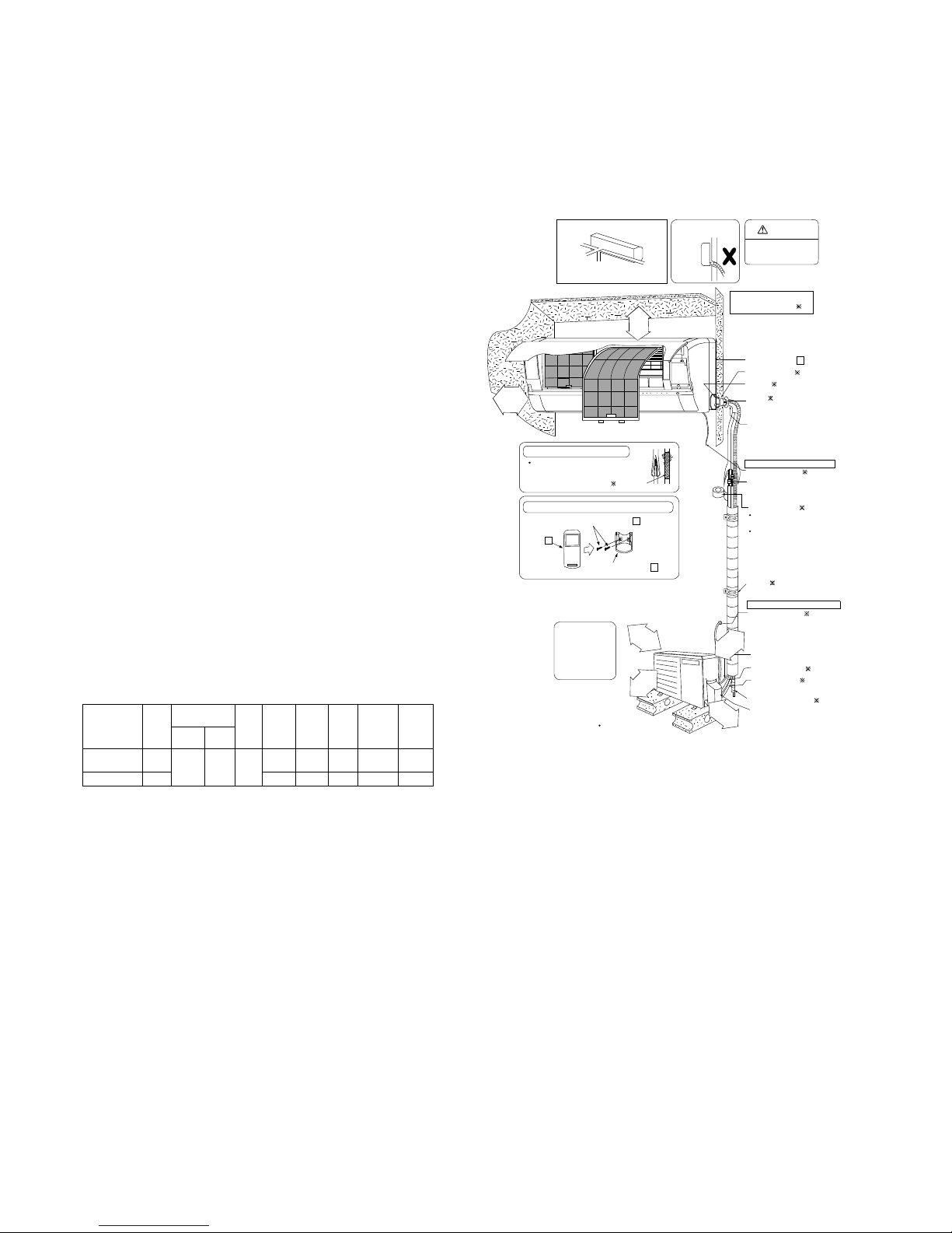
12.1.3 Indoor/Outdoor Unit Installation
Diagram
Vinyl tape
Remote con trol holder fixing s crews
6
Remote control holder
5
Remote
control
3
This illustration is for
explanation purposes only.
The indoor unit will actually face a different way.
1
0
0
mm
o
r
mo
r
e
1
0
0
0
m
m
o
r
m
or
e
1
0
0
mm
o
r
m
o
re
3
0
0
m
m
o
r
m
o
r
e
It is advisable to
avoid more than 2
blockage directions.
For better ventilation
& multiple-outdoor
installation, please
consult aut horized
dealer/ specialist.
Saddle
Power supply c ord
Additional drain hose
Control Board cover
Gas side piping
Connection cable
Vinyl tape (wide)
Apply after carrying
out a dr ainage test.
To carry out the
drainage test,
remove the air fi lters
and pour wat er into
the heat exchanger.
Liquid side piping
Piping direction
Attention not to bend
up drain hose
Right
Right
Rear
Right
bottom
Left
(Front side)
Carry out insulation after
checking for gas leaks and
secure with vinyl tape.
Attaching the remote control holder to the wall
Insulation of piping connections
( )
( )
( )
( )
( )
( )
WARNING
Flare connection
only at outside
of building
Installation plate
1
Sleeve
Bushing-Sleeve
Bend the pipe as
closely on t he wall as
possible, but be careful
that it doesn’t break.
Putty
(Gum Type Sealer)
Installation parts you
should purchase
( )
( )
( )
( )
Flare connection
only at outside
of building
50 mm
or more
65 mm
or more
(Left and right are identical)
Power supply cord
( )
In case of indoor power supply
In case of outdoor power supply
 Loading...