

Panasonic CS-E9SD3UAW, CS-E12SD3UAW, CS-E18SD3UAW, CU-E9SD3UA, CU-E12SD3UA service manual
...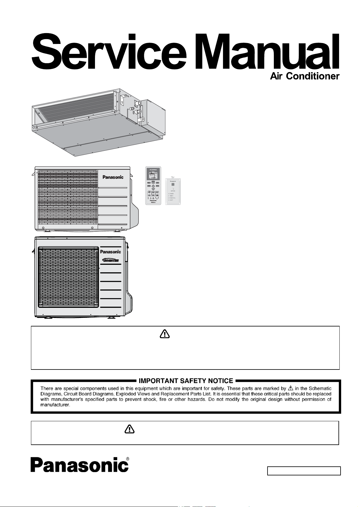
Order No: PAPAMY1604052CE
Indoor Unit Outdoor Unit
CS-E9SD3UAW
CS-E12SD3UAW
CS-E18SD3UAW
CU-E9SD3UA
CU-E12SD3UA
CU-E18SD3UA
Destination
USA
This service information is designed for experienced repair technicians only and is not designed for use by the general public.
It does not contain warnings or cautions to advise non-technical individuals of potential dangers in attempting to service a product.
Products powered by electricity should be serviced or repaired only by experienced professional technicians. Any attempt to service
or repair the product or products dealt with in this service information by anyone else could result in serious injury or death.
PRECAUTION OF LOW TEMPERATURE
In order to avoid frostbite, be assured of no refrigerant leakage during the installation or repairing of refrigerant circuit.
WARNING
© Panasonic Corporation 2016

TABLE OF CONTENTS
PAGE PAGE
1. Safety Precautions ............................................. 3
2. Specifications ..................................................... 5
3. Features ............................................................. 14
4. Location of Controls and Components .......... 15
4.1 Indoor Unit .................................................. 15
4.2 Outdoor Unit ............................................... 15
4.3 Remote Control .......................................... 15
5. Dimensions ....................................................... 16
5.1 Indoor Unit .................................................. 16
5.2 Outdoor Unit ............................................... 17
6. Refrigeration Cycle Diagram ........................... 18
6.1 CS-E9SD3UAW CU-E9SD3UA .................. 18
6.2 CS-E12SD3UAW CU-E12SD3UA .............. 19
6.3 CS-E18SD3UAW CU-E18SD3UA .............. 20
7. Block Diagram .................................................. 21
7.1 CS-E9SD3UAW CU-E9SD3UA
CS-E12SD3UAW CU-E12SD3UA .............. 21
7.2 CS-E18SD3UAW CU-E18SD3UA .............. 22
8. Wiring Connection Diagram ............................ 23
8.1 Indoor Unit .................................................. 23
8.2 Outdoor Unit ............................................... 24
9. Electronic Circuit Diagram .............................. 26
9.1 Indoor Unit .................................................. 26
9.2 Outdoor Unit ............................................... 27
10. Printed Circuit Board ....................................... 29
10.1 Indoor Unit .................................................. 29
10.2 Outdoor Unit ............................................... 30
11. Installation Instruction ..................................... 33
11.1 Indoor Unit .................................................. 35
11.2 Outdoor Unit ............................................... 43
12. Operation and Control ..................................... 48
12.1 Basic Function ............................................ 48
12.2 Quiet Operation (Cooling Mode/Cooling
Area of Soft Dry Mode) ............................... 51
12.3 Powerful Mode Operation ........................... 52
12.4 Timer Control .............................................. 52
12.5 Auto Restart Control ................................... 52
12.6 Indication Panel .......................................... 52
12.7 Electric Heater Control 1 ............................ 53
12.8 Electric Heater Control 2 ............................ 54
14.1 TEST RUN OPERATION (FOR PUMP
DOWN/SERVICING PURPOSE) ...............60
14.2 Auto OFF/ON Button ..................................61
14.3 Cooling Only Operation (Single connection
Only, Multi connection please refer to Multi
outdoor manual) .........................................62
14.4 Remote Controller Room Temperature
Thermoshift Control ....................................63
15. Troubleshooting Guide ....................................67
15.1 Refrigeration Cycle System ........................67
15.2 Relationship Between the Condition of the
Air Conditioner and Pressure and Electric
Current ........................................................68
15.3 Breakdown Self Diagnosis Function ...........69
15.4 Error Codes Table ......................................70
15.5 Self-diagnosis Method ................................72
16. Disassembly and Assembly Instructions ......96
16.1 Indoor Electronic Controller, Blower Fan,
Fan Motor & Drain Motor Removal
16.2 Outdoor Electronic Controller Removal
17. Technical Data ............................................... 101
17.1 Technical data provided are based on the
17.2 Technical data provided are based on the
17.3 Fan Performance ..................................... 107
18. Service Data ................................................... 110
18.1 Cool Mode Outdoor Air Temperature
18.2 Heat Mode Outdoor Air Temperature
18.3 Piping Length Correction Factor .............. 116
19. Exploded View and Replacement Parts
19.1 Indoor Unit ............................................... 118
19.2 Outdoor Unit ............................................ 120
Procedure. ..................................................96
Procedure ...................................................99
air conditioner running under free
frequency. ................................................ 101
air conditioner running under rated
frequency. ................................................ 104
Characteristic ........................................... 110
Characteristic ........................................... 113
List .................................................................. 118
13. Protection Control ............................................ 55
13.1 Protection Control For All Operations ......... 55
13.2 Protection Control For Cooling & Soft Dry
Operation .................................................... 56
13.3 Protection Control for Heating
Operation .................................................... 58
14. Servicing Mode ................................................. 60
2
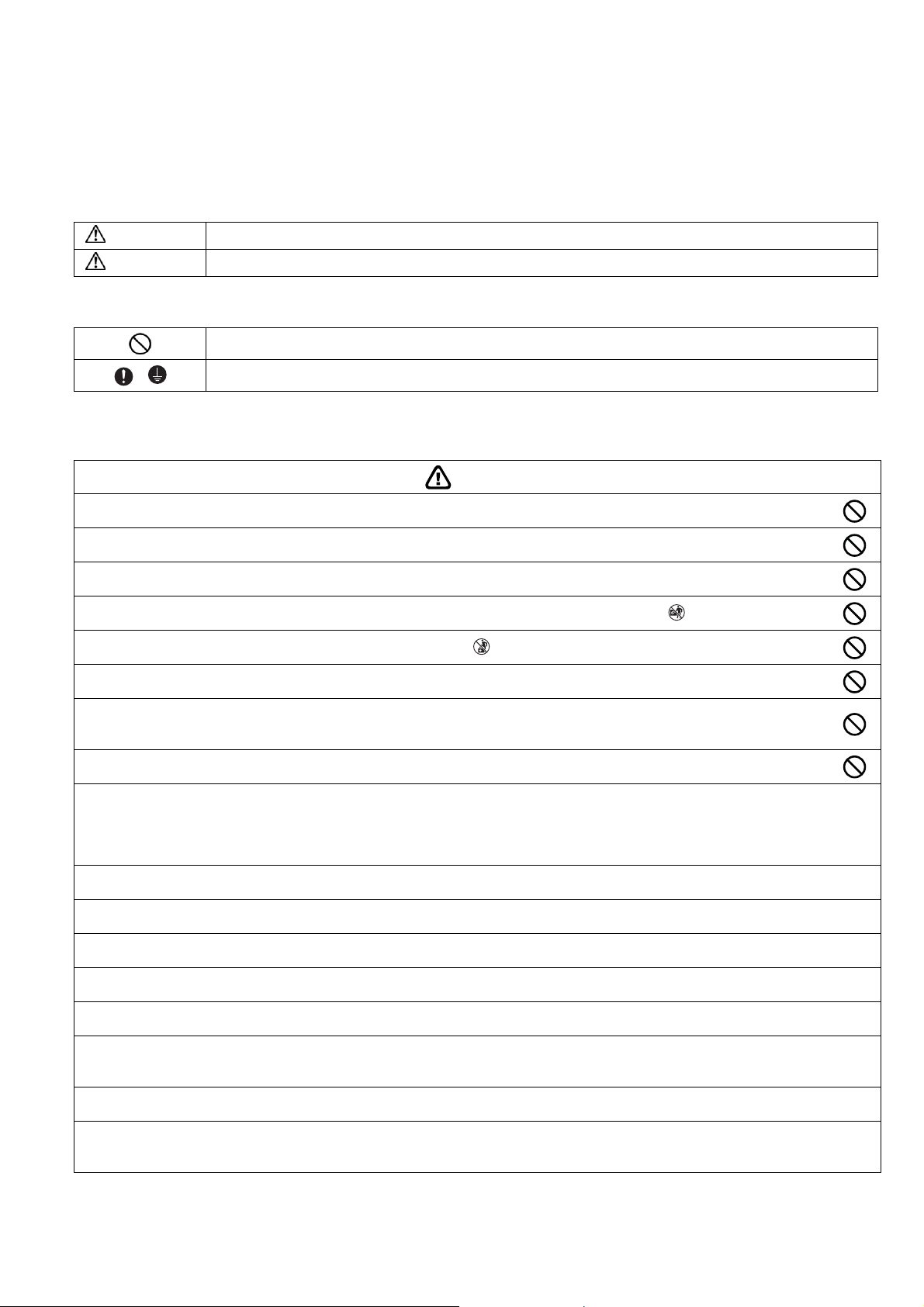
1. Safety Precautions
Read the following “SAFETY PRECAUTIONS” carefully before installation.
Electrical work must be installed by a licensed electrician. Be sure to use the correct rating of the power plug and main circuit
for the model to be installed.
The caution items stated here must be followed because these important contents are related to safety. The meaning of each
indication used is as below. Incorrect installation due to ignoring of the instruction will cause harm or damage, and the
seriousness is classified by the following indications.
WARNING
CAUTION
The items to be followed are classified by the symbols:
Carry out test running to confirm that no abnormality occurs after the installation. Then, explain to user the operation, care
and maintenance as stated in instructions. Please remind the customer to keep the operating instructions for future reference.
This indication shows the possibility of causing death or serious injury.
This indication shows the possibility of causing injury or damage to properties only.
Symbol with white background denotes item that is PROHIBITED.
Symbol with dark background denotes item that must be carried out.
WARNING
Do not install outdoor unit near handrail of veranda. When installing air-conditioner unit on veranda of a high rise building, child
1.
may climb up to outdoor unit and cross over the handrail causing an accident.
Do not use unspecified cord, modified cord, joint cord or extension cord for power supply cord. Do not share the single outlet
2.
with other electrical appliances. Poor contact, poor insulation or over current will cause electrical shock or fire.
3. Do not tie up the power supply cord into a bundle by band. Abnormal temperature rise on power supply cord may happen.
4.
Do not insert your fingers or other objects into the unit, high speed rotating fan may cause injury.
5.
Do not sit or step on the unit, you may fall down accidentally.
6. Keep plastic bag (packaging material) away from small children, it may cling to nose and mouth and prevent breathing.
When installing or relocating air conditioner, do not let any substance other than the specified refrigerant, eg. air etc mix into
7.
refrigeration cycle (piping). Mixing of air etc will cause abnormal high pressure in refrigeration cycle and result in explosion,
injury etc.
8. Do not add or replace refrigerant other than specified type. It may cause product damage, burst and injury etc.
For R410A model, use piping, flare nut and tools which is specified for R410A refrigerant. Using of existing (R22) piping, flare nut
and tools may cause abnormally high pressure in the refrigerant cycle (piping), and possibly result in explosion and injury.
9.
Thickness for copper pipes used with R410A must be more than 1/32" (0.8 mm). Never use copper pipes thinner than
1/32" (0.8 mm).
It is desirable that the amount of residual oil less than 0.0008 oz/ft (40 mg/10 m).
Engage authorized dealer or specialist for installation. If installation done by the user is incorrect, it will cause water leakage, electrical
10.
shock or fire.
11. Install according to this installation instructions strictly. If installation is defective, it will cause water leakage, electrical shock or fire.
Use the attached accessories parts and specified parts for installation. Otherwise, it will cause the set to fall, water leakage, fire or
12.
electrical shock.
Install at a strong and firm location which is able to withstand the set’s weight. If the strength is not enough or installation is not properly
13.
done, the set will drop and cause injury.
For installation work, follow all electrical, building, plumbing, local codes, regulations and these installation instructions. If electrical circuit
14.
capacity is not enough or a defect is found in electrical work, it will cause electrical shock or fire.
Do not use spliced wires for indoor/outdoor connection cable. Use the specified indoor/outdoor connection cable, refer to instruction
15.
CONNECT THE CABLE TO THE INDOOR/OUTDOOR UNIT and connect tightly for indoor/outdoor connection. Clamp the cable so that
no external force will have impact on the terminal. If connection or fixing is not perfect, it will cause heat-up or fire at the connection.
Wire routing must be properly arranged so that control board cover is fixed properly. If control board cover is not fixed perfectly, it will
16.
cause fire or electrical shock.
This equipment must installed with an Earth Leakage Circuit Breaker (ELCB) or Ground Fault Current Interrupter (GFCI) or Appliance
17.
Leakage Current Interrupter (ALCI) that has been certified by an NRTL Certified Testing Agency and that is suitable for the voltages and
amperages involved. Otherwise, if may cause electrical shock and fire in case of equipment breakdown.
3
During installation, install the refrigerant piping properly before running the compressor. Operation of compressor without fixing
18.
refrigeration piping and valves at opened condition will cause suck-in of air, abnormal high pressure in refrigeration cycle and result in
explosion, injury etc.
During pump down operation, stop the compressor before removing the refrigeration piping. Removal of refrigeration piping while
19.
compressor is operating and valves are opened will cause suck-in of air, abnormal high pressure in refrigeration cycle and result in
explosion, injury etc.
Tighten the flare nut with torque wrench according to specified method. If the flare nut is over-tightened, after a long period, the flare
20.
may break and cause refrigerant gas leakage.
After completion of installation, confirm there is no leakage of refrigerant gas. It may generate toxic gas when the refrigerant comes into
21.
contact with fire.
22. Ventilate if there is refrigerant gas leakage during operation. It may cause toxic gas when the refrigerant comes into contact with fire.
This equipment must be properly earthed. Earth line must not be connected to gas pipe, water pipe, earth of lightning rod and telephone.
23.
Otherwise, it may cause electrical shock in case of equipment breakdown or insulation breakdown.
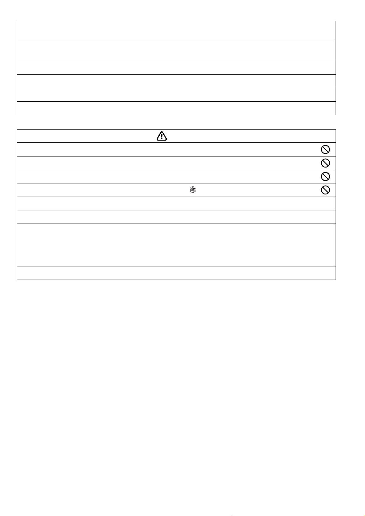
CAUTION
Do not install the unit at place where leakage of flammable gas may occur. In case gas leaks and accumulates at surrounding
1.
of the unit, it may cause fire.
Do not release refrigerant during piping work for installation, re-installation and during repairing a refrigeration parts. Take care
2.
of the liquid refrigerant, it may cause frostbite.
3. Do not install this appliance in a laundry room or other location where water may drip from the ceiling, etc.
4.
Do not touch the sharp aluminium fin, sharp parts may cause injury.
Carry out drainage piping as mentioned in installation instructions. If drainage is not perfect, water may enter the room and damage the
5.
furniture.
6. Select an installation location which is easy for maintenance.
Power supply connection to the room air conditioner.
Power supply cord shall be UL listed or CSA approved 3 conductor with minimum AWG14 (E9SD3UAW, E12SD3UAW) and AWG12
(E18SD3UAW) wires.
7.
Power supply point should be in an easily accessible place for power disconnection in case of emergency.
In some countries, permanent connection of this air conditioner to the power supply is prohibited.
Fix power supply connection to a circuit breaker for permanent connection.
Use NRTL approved fuse or circuit breaker (rating refers to name plate) for permanent connection.
Installation work.
8.
It may take two people to carry out the installation work.
4
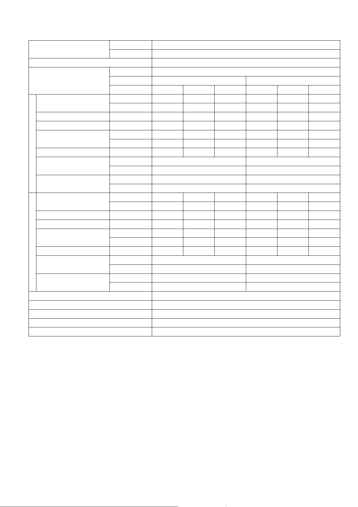
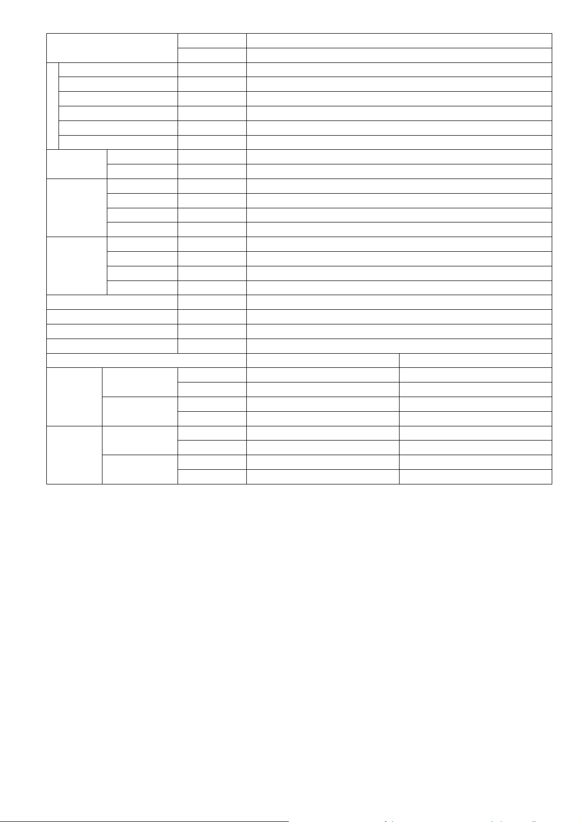
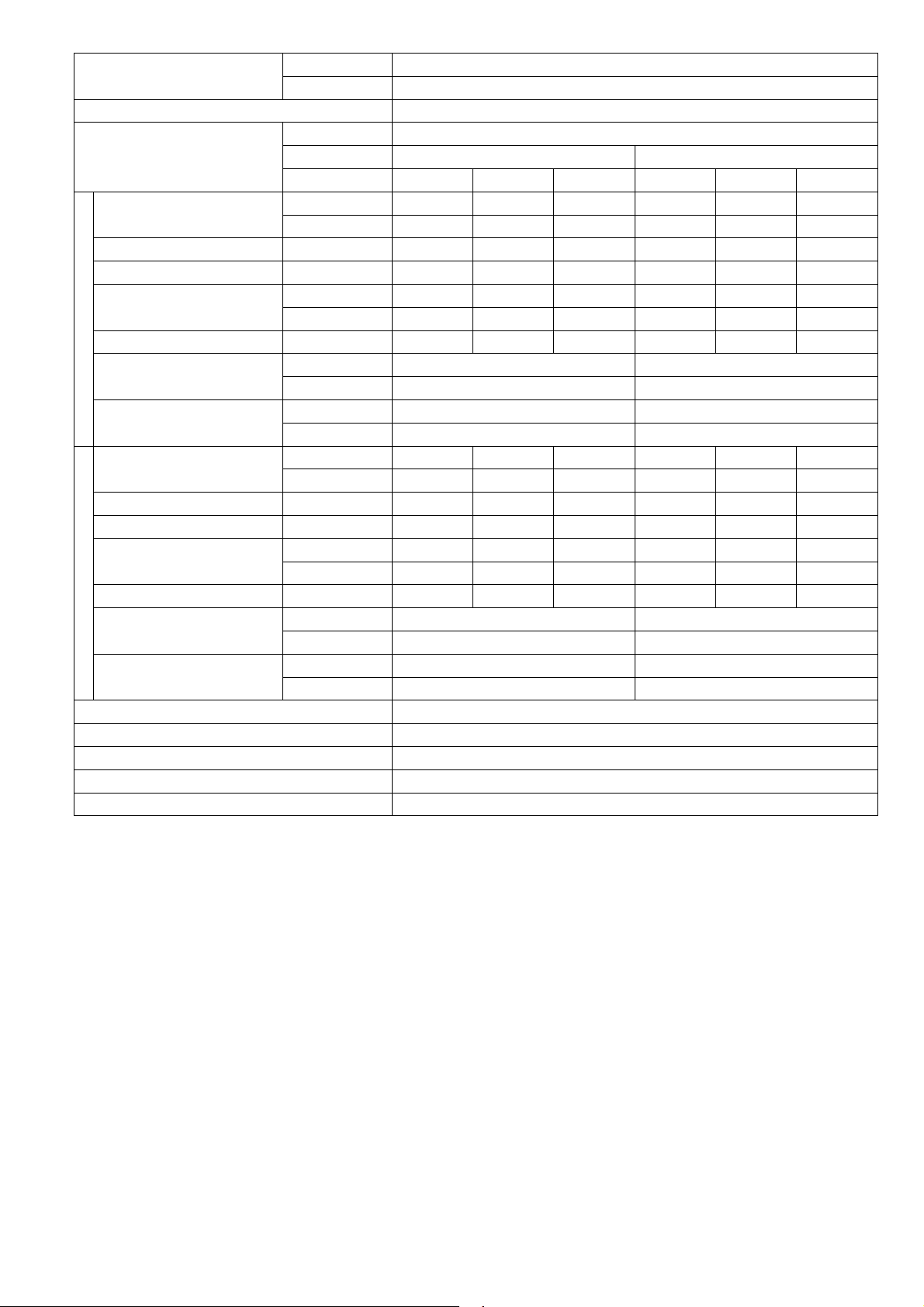
2. Specifications
MODEL
Performance Test Condition ARI
Power Supply
Capacity
Running Current A - 3.6 - - 3.2 -
Input Power W 250 690 850 250 690 850
EER
Cooling
Heating
Power Factor % - 92 - - 94 -
Indoor Noise (H / L / QLo)
Outdoor Noise (H / L / QLo)
Capacity
Running Current A - 5.7 - - 5.1 -
Input Power W 200 1.12k 1.50k 200 1.12k 1.50k
COP
Power Factor % - 96 - - 97 -
Indoor Noise (H / L / QLo)
Outdoor Noise (H / L / QLo)
Min Circuit Ampacity 15.00
Max. Overcurrent Protection 15.00
Max Current (A) / Max Input Power (W) 7.0 / 1.57k
Starting Current (A) 5.70
SEER/HSPF 20.50 / 10.00
INDOOR CS-E9SD3UAW
OUTDOOR CU-E9SD3UA
Phase, Hz Single, 60
V 208 230
Min. Mid. Max. Min. Mid. Max.
kW 1.20 2.64 3.00 1.20 2.64 3.00
BTU/h 4100 9000 10200 4100 9000 10200
W/W 4.80 3.82 3.53 4.80 3.82 3.53
BTU/hW 16.40 13.00 12.00 16.40 13.00 12.00
dB-A 35 / 28 / 25 35 / 28 / 25
Power Level dB 51 / - / - 51 / - / -
dB-A 48 / - / - 48 / - / -
Power Level dB 63 / - / - 63 / - / -
kW 1.20 3.51 4.14 1.20 3.51 4.14
BTU/h 4100 12000 14100 4100 12000 14100
W/W 6.00 3.12 2.76 6.00 3.12 2.76
BTU/hW 20.50 10.70 9.40 20.50 10.70 9.40
dB-A 35 / 28 / 25 35 / 28 / 25
Power Level dB 51 / - / - 51 / - / -
dB-A 50 / - / - 50 / - / -
Power Level dB 65 / - / - 65 / - / -
5

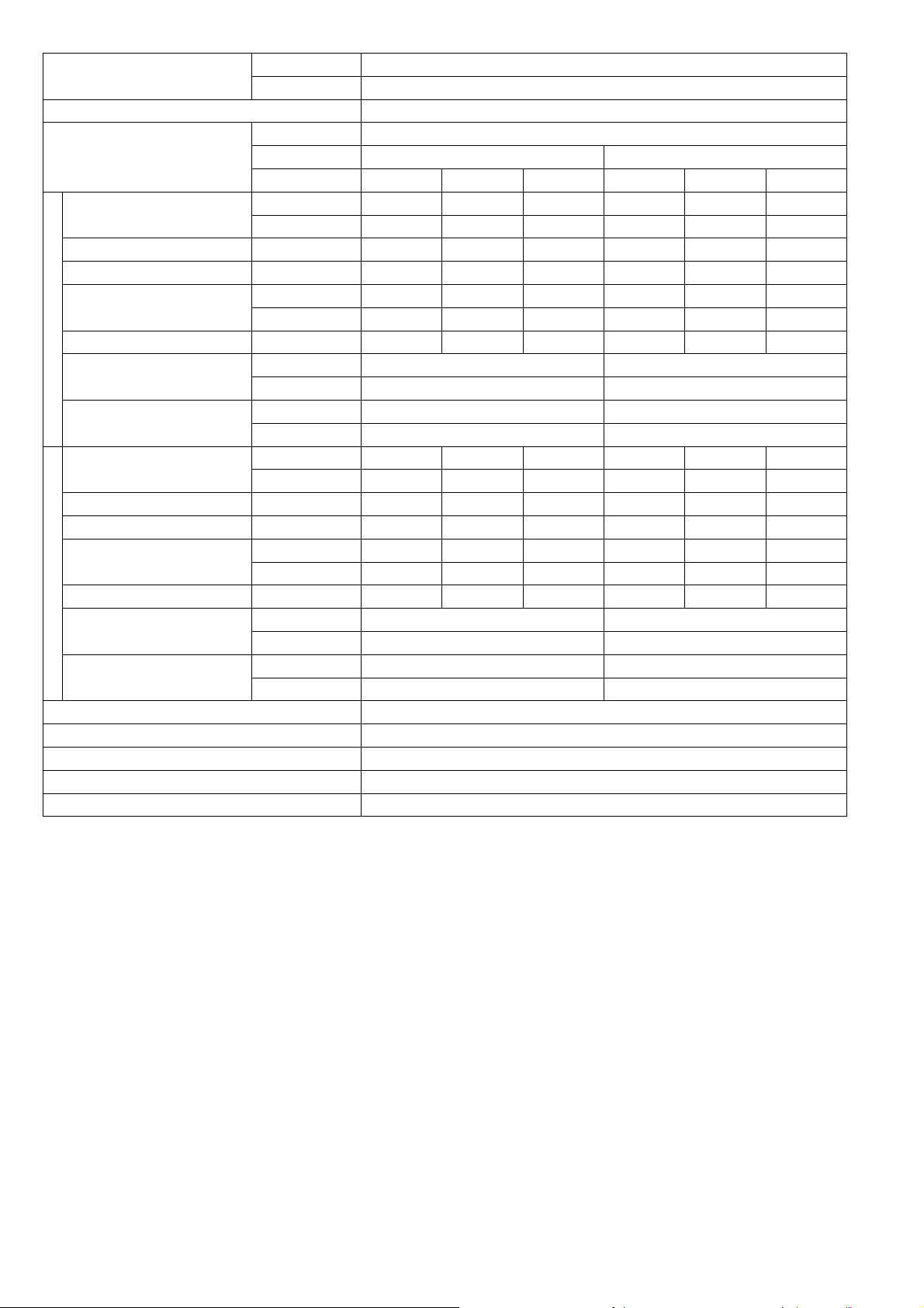
MODEL
INDOOR
OUTDOOR CU-E9SD3UA
CS-E9SD3U
Type Hermetic Motor / Rotary
Compressor
Motor Type Brushless (4-poles)
Output Power 700
Type Sirocco
Material GFZ010A / GF20
Motor Type DC Motor (8-poles)
Output Power W 51
Cool rpm
Heat rpm 800
Cool rpm 940
Heat rpm 880
Cool rpm
1120
Heat rpm 1090
Cool rpm
1300
Heat rpm 1300
Cool rpm
Heat rpm
1380
1380
Indoor Fan
Speed
QLo
Lo
Me
Hi
SHi
Type Propeller Fan
Material PP
Motor Type DC Motor (8-poles)
Output Power W 40
Outdoor Fan
Speed Hi
Cool rpm 830
Heat rpm 780
Moisture Removal L/h (Pt/h) 0.6 (1.3)
3
QLo
Lo
Indoor Airflow
Me
Hi
SHi
Outdoor Airflow Hi
Cool m
Heat m3/min (ft3/min) 8.50 (300)
Cool m
Heat m3/min (ft3/min) 9.30 (328)
Cool m
Heat m3/min (ft3/min) 11.40 (403)
Cool m
Heat m3/min (ft3/min) 13.50 (475)
Cool m
Heat m3/min (ft3/min) 14.30 (505)
Cool m
Heat m3/min (ft3/min) 31.0 (1095)
/min (ft3/min) 9.30 (328)
3
/min (ft3/min) 9.90 (350)
3
/min (ft3/min) 11.70 (413)
3
/min (ft3/min) 13.50 (475)
3
/min (ft3/min) 14.30 (505)
3
/min (ft3/min) 31.0 (1095)
Control Device Expansion Valve
Refrigeration
Cycle
Refrigerant Oil cm
3
FV50S (320)
Refrigerant Type g (oz) R410A, 980 (34.6)
Height (I/D / O/D) mm (inch) 200 (7-7/8) / 542 (21-11/32)
Dimension
Width (I/D / O/D) mm (inch) 750 (29-17/32) / 780 (30-23/32)
Depth (I/D / O/D) mm (inch) 640 (25-7/32) / 289 (11-13/32)
Weight Net (I/D / O/D) kg (lb) 19 (42) / 37 (82)
AW
880
6
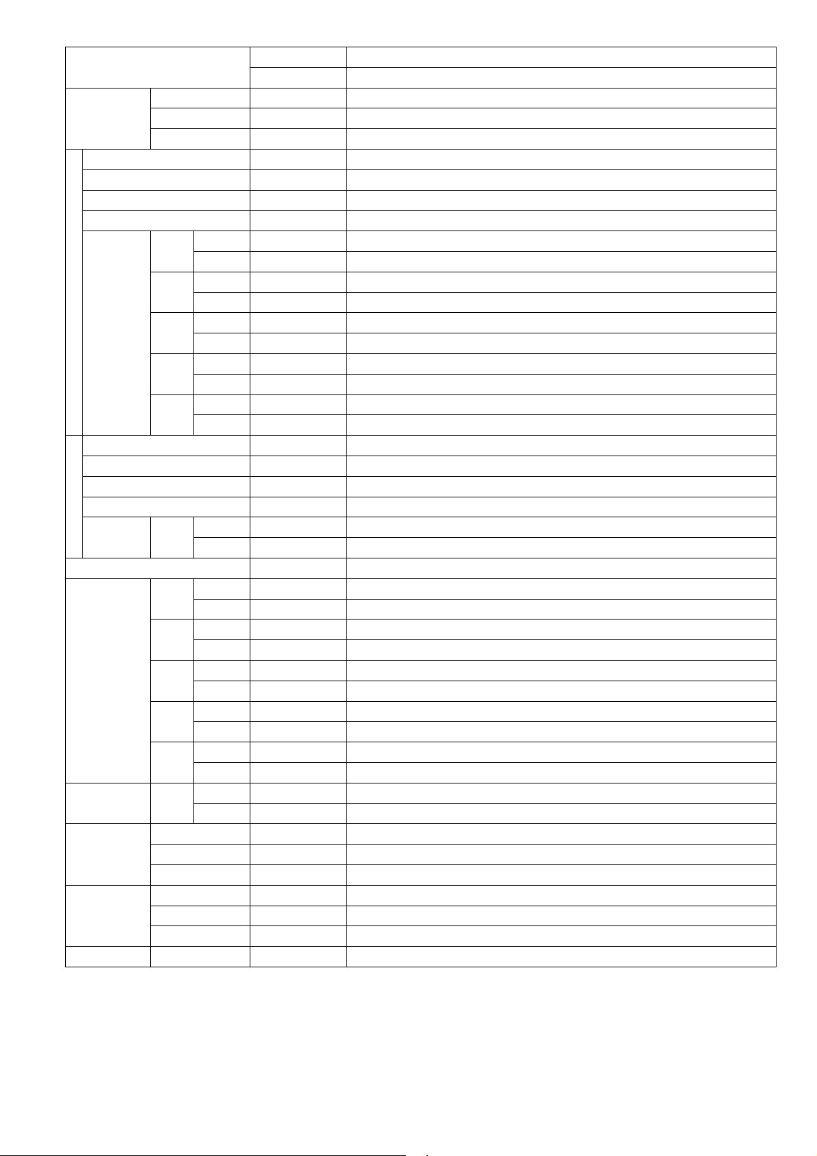
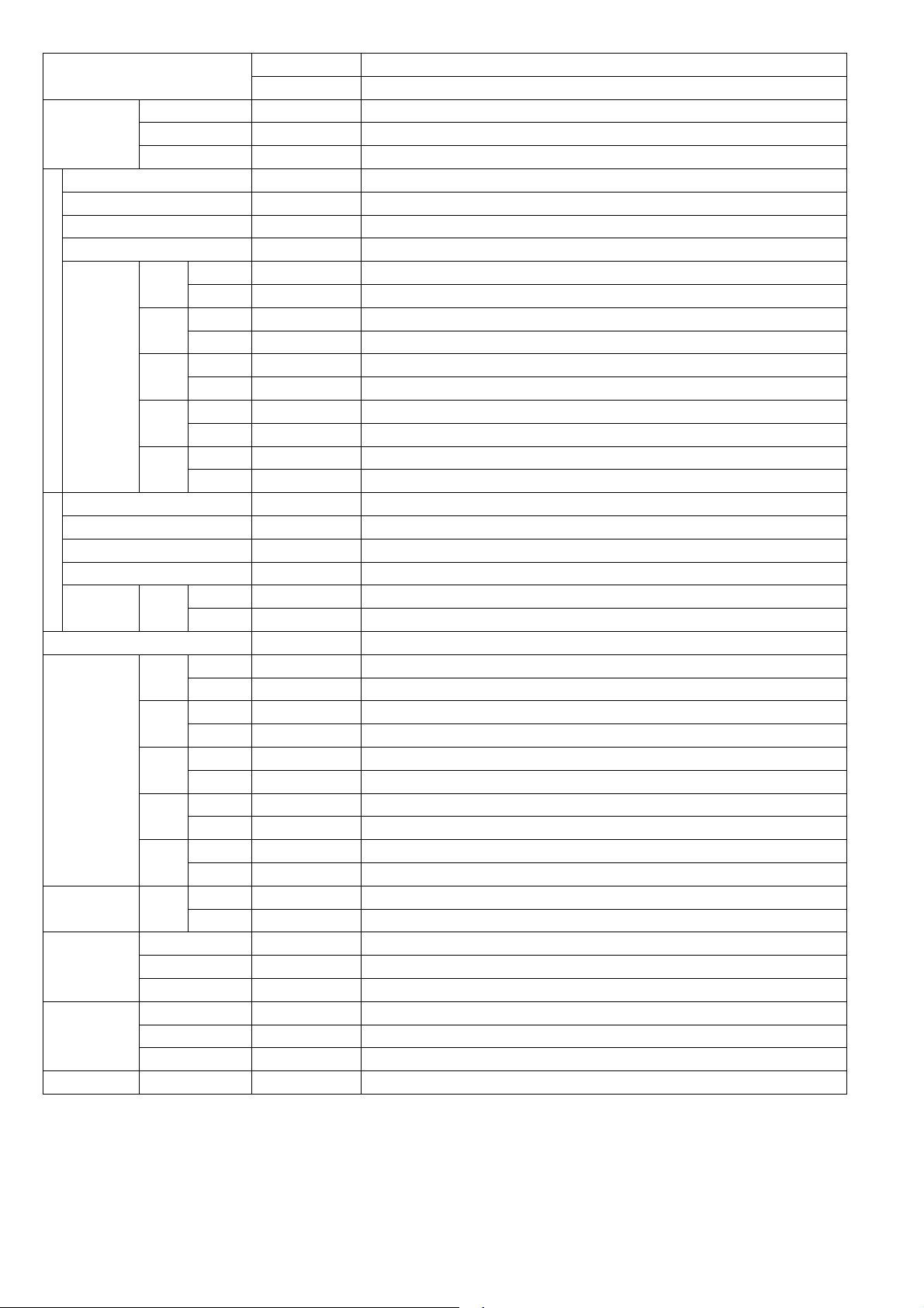
MODEL
Pipe Diameter (Liquid / Gas) mm (inch) 6.35 (1/4) / 9.52 (3/8)
Standard Length m (ft) 7.5 (24.6)
Length Range (min - max) m (ft) 3 (9.8) ~ 20 (65.6)
I/D & O/D Height Different m (ft) 15 (49.2)
Piping
Additional Gas Amount g/m (oz/ft) 20 (0.2)
Length for Additional Gas m (ft) 7.5 (24.6)
Drain Hose
Indoor Heat
Exchanger
Outdoor Heat
Exchanger
Power Supply Cord A Nil
Protection Device Electronic Control
Indoor
Operation
Range
Outdoor
Operation
Range
Inner Diameter mm/inch 16 / 0.63
Length mm/inch 117.5 / 4.63
Fin Material Aluminium (Pre Coat)
Fin Type Slit Fin
Row x Stage x FPI 3 x 12 x 18
Size (W x H x L) mm 590 x 282 x 38.1
Fin Material Aluminium (Blue Coat)
Fin Type Corrugated Fin
Row x Stage x FPI 2 x 24 x 17
Size (W x H x L) mm 36.4 x 504 x 713:684
Power Supply Outdoor Power Supply
Thermostat Electronic Control
Cooling
Heating
Cooling
Heating
INDOOR
OUTDOOR CU-E9SD3UA
Dry Bulb Wet Bulb
Maximum °C/°F 32 / 89.6 23 / 73.4
Minimum °C/°F 16 / 60.8 11 / 51.8
Maximum °C/°F 30 / 86.0
Minimum °C/°F 16 / 60.8 - / -
Maximum °C/°F 46 / 114.8 26 / 78.8
Minimum °C/°F -17.8 / 0 - / -
Maximum °C/°F 24 / 75.2 18 / 64.4
Minimum °C/°F -20 / -4 -21 / -5.8
CS-E9SD3U
AW
- / -
1.
Cooling capacities are based on indoor temperature of 27°C Dry Bulb (80.6°F Dry Bulb), 19.0°C Wet Bulb (66.2°F Wet Bulb) and outdo
temperatu
2.
Heating capacities are based on indoor temperature of 20°C Dry Bulb (68°F Dry Bulb) and outdoor air temperature of 7°C Dry Bulb
(44.6°F Dry Bulb), 6°C Wet Bulb (42.8°F Wet Bulb)
3 Heating low temperature capacity, Input Power and COP measured at 230 V, indoor temperature 20°C (68°F), outdoor 2/1°C (35°F/33.8°F)
4 Heating extreme low temperature capacity, Input Power and COP measured at 230 V indoor temperature 20°C (68°F), outdoor -7/-8°C
(19.4°F/17.6°F)
5.
Standby power consumption ≤0.7W (when switched OFF by remote control, except under self protection control).
Specifications are subjected to change without notice for further improvement.
6.
re of 35°C Dry Bulb (95°F Dry Bulb), 24°C Wet Bulb (75.2°F Wet Bulb)
or air
7
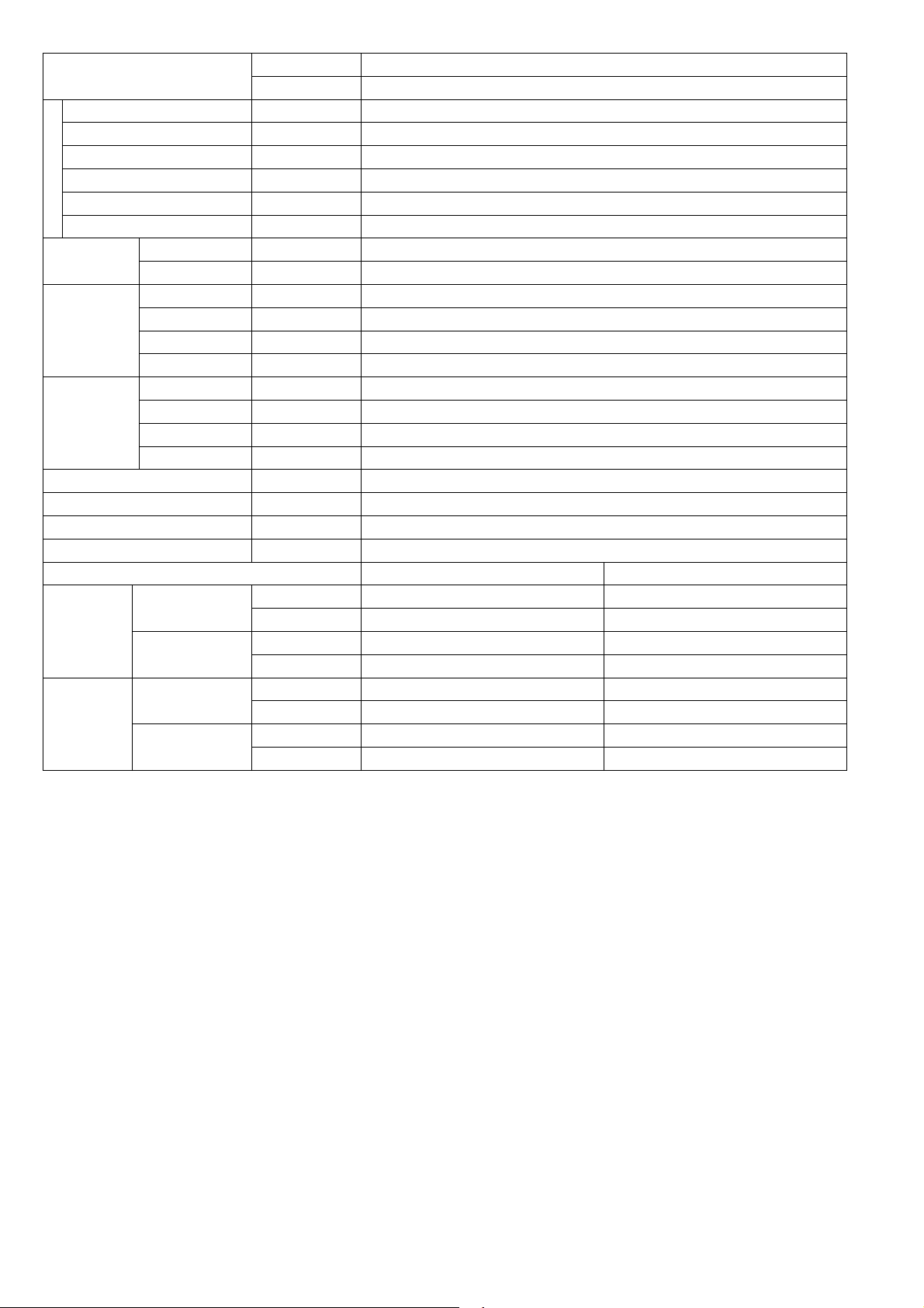
MODEL
Performance Test Condition ARI
Power Supply
Capacity
Running Current A - 4.7 - - 4.2 -
Input Power W 250 920 1.15k 250 920 1.15k
EER
Cooling
Heating
Power Factor % - 94 - - 95 -
Indoor Noise (H / L / QLo)
Outdoor Noise (H / L / QLo)
Capacity
Running Current A - 6.3 - - 5.6 -
Input Power W 200 1.25k 1.71k 200 1.25k 1.71k
COP
Power Factor % - 95 - - 97 -
Indoor Noise (H / L / QLo)
Outdoor Noise (H / L / QLo)
Min Circuit Ampacity 15.00
Max. Overcurrent Protection 15.00
Max Current (A) / Max Input Power (W) 7.8 / 1.71k
Starting Current (A) 6.30
SEER/HSPF 20.00 / 10.00
INDOOR
OUTDOOR CU-E12SD3UA
Phase, Hz Single, 60
V 208 230
Min. Mid. Max. Min. Mid. Max.
kW 1.20 3.36 3.90 1.20 3.36 3.90
BTU/h 4100 11500 13300 4100 4100 13300
W/W 4.80 3.64 3.39 4.80 3.64 3.39
BTU/hW 16.40 12.50 11.55 16.40 12.50 11.55
dB-A 35 / 28 / 25 35 / 28 / 25
Power Level dB 51 / - / - 51 / - / -
dB-A 49 / - / - 49 / - / -
Power Level dB 64 / - / - 64 / - / -
kW 1.20 4.05 4.77 1.20 4.05 4.77
BTU/h 4100 13800 16300 4100 13800 16300
W/W 6.00 3.24 2.79 6.00 3.24 2.79
BTU/hW 20.50 11.00 9.50 20.50 11.00 9.50
dB-A 35 / 28 / 25 35 / 28 / 25
Power Level dB 51 / - / - 51 / - / -
dB-A 51 / - / - 51 / - / -
Power Level dB 66 / - / - 66 / - / -
CS-E12SD3UAW
8
MODEL
INDOOR
OUTDOOR CU-E12SD3UA
CS-E12SD3UAW
Type Hermetic Motor / Rotary
Compressor
Motor Type Brushless (4-poles)
Output Power 700
Type Sirocco
Material GFZ010A / GF20
Motor Type DC Motor (8-poles)
Output Power W 51
Cool rpm
Heat rpm 800
Cool rpm 940
Heat rpm 880
Cool rpm
1120
Heat rpm 1090
Cool rpm
1300
Heat rpm 1300
Cool rpm
Heat rpm
1430
1430
Indoor Fan
Speed
QLo
Lo
Me
Hi
SHi
Type Propeller Fan
Material PP
Motor Type DC Motor (8-poles)
Output Power W 40
Outdoor Fan
Speed Hi
Cool rpm 830
Heat rpm 820
Moisture Removal L/h (Pt/h) 0.8 (1.7)
3
QLo
Lo
Indoor Airflow
Me
Hi
SHi
Outdoor Airflow Hi
Cool m
Heat m3/min (ft3/min) 8.50 (300)
Cool m
Heat m3/min (ft3/min) 9.30 (328)
Cool m
Heat m3/min (ft3/min) 11.40 (403)
Cool m
Heat m3/min (ft3/min) 13.50 (475)
Cool m
Heat m3/min (ft3/min) 14.80 (523)
Cool m
Heat m3/min (ft3/min) 31.2 (1100)
/min (ft3/min) 9.30 (328)
3
/min (ft3/min) 9.90 (350)
3
/min (ft3/min) 11.70 (413)
3
/min (ft3/min) 13.50 (475)
3
/min (ft3/min) 14.80 (523)
3
/min (ft3/min) 31.2 (1100)
Control Device Expansion Valve
Refrigeration
Cycle
Refrigerant Oil cm
3
FV50S (320)
Refrigerant Type g (oz) R410A, 1.08k (38.1)
Height (I/D / O/D) mm (inch) 200 (7-7/8) / 542 (21-11/32)
Dimension
Width (I/D / O/D) mm (inch) 750 (29-17/32) / 780 (30-23/32)
Depth (I/D / O/D) mm (inch) 640 (25-7/32) / 289 (11-13/32)
Weight Net (I/D / O/D) kg (lb) 19 (42) / 37 (82)
880
9
MODEL
Pipe Diameter (Liquid / Gas) mm (inch) 6.35 (1/4) / 12.70 (1/2)
Standard Length m (ft) 7.5 (24.6)
Length Range (min - max) m (ft) 3 (9.8) ~ 20 (65.6)
I/D & O/D Height Different m (ft) 15 (49.2)
Piping
Additional Gas Amount g/m (oz/ft) 20 (0.2)
Length for Additional Gas m (ft) 7.5 (24.6)
Drain Hose
Indoor Heat
Exchanger
Outdoor Heat
Exchanger
Power Supply Cord A Nil
Protection Device Electronic Control
Indoor
Operation
Range
Outdoor
Operation
Range
1. Cooling capacities are based on indoor temperature of 27°C Dry Bulb (80.6°F Dry Bulb), 19.0°C Wet Bulb (66.2°F Wet Bulb) and outdoor air
temperature of 35°C Dry Bulb (95°F Dry Bulb), 24°C Wet Bulb (75.2°F Wet Bulb)
2. Heating capacities are based on indoor temperature of 20°C Dry Bulb (68°F Dry Bulb) and outdoor air temperature of 7°C Dry Bulb
(44.6°F Dry Bulb), 6°C Wet Bulb (42.8°F Wet Bulb)
3 Heating low temperature capacity, Input Power and COP measured at 230 V, indoor temperature 20°C (68°F), outdoor 2/1°C (35°F/33.8°F)
4 Heating extreme low temperature capacity, Input Power and COP measured at 230 V indoor temperature 20°C (68°F), outdoor -7/-8°C
(19.4°F/17.6°F)
5. Standby power consumption ≤0.7W (when switched OFF by remote control, except under self protection control).
6. Specifications are subjected to change without notice for further improvement.
Inner Diameter mm/inch 16 / 0.63
Length mm/inch 117.5 / 4.63
Fin Material Aluminium (Pre Coat)
Fin Type Slit Fin
Row x Stage x FPI 3 x 12 x 18
Size (W x H x L) mm 590 x 282 x 38.1
Fin Material Aluminium (Blue Coat)
Fin Type Corrugated Fin
Row x Stage x FPI 2 x 24 x 17
Size (W x H x L) mm 36.4 x 504 x 824:794
Power Supply Outdoor Power Supply
Thermostat Electronic Control
Dry Bulb Wet Bulb
Cooling
Heating
Cooling
Heating
INDOOR CS-E12SD3UAW
OUTDOOR CU-E12SD3UA
Maximum °C/°F 32 / 89.6 23 / 73.4
Minimum °C/°F 16 / 60.8 11 / 51.8
Maximum °C/°F 30 / 86.0 - / -
Minimum °C/°F 16 / 60.8 - / -
Maximum °C/°F 46 / 114.8 26 / 78.8
Minimum °C/°F -17.8 / 0 - / -
Maximum °C/°F 24 / 75.2 18 / 64.4
Minimum °C/°F -20 / -4 -21 / -5.8
10
MODEL
Performance Test Condition ARI
Power Supply
Capacity
Running Current A - 8.5 - - 7.6 -
Input Power W 430 1.58k 1.82k 430 1.58k 1.82k
EER
Cooling
Heating
Power Factor % - 89 - - 90 -
Indoor Noise (H / L / QLo)
Outdoor Noise (H / L / QLo)
Capacity
Running Current A - 9.8 - - 8.7 -
Input Power W 380 1.83k 2.18k 380 1.83k 2.18k
COP
Power Factor % - 90 - - 91 -
Indoor Noise (H / L / QLo)
Outdoor Noise (H / L / QLo)
Min Circuit Ampacity 20.0
Max. Overcurrent Protection 25.0
Max Current (A) / Max Input Power (W) 13.7 / 3.06k
Starting Current (A) 9.80
INDOOR CS-E18SD3UAW
OUTDOOR CU-E18SD3UA
Phase, Hz Single, 60
V 208 230
Min. Mid. Max. Min. Mid. Max.
kW 1.70 5.04 5.70 1.70 5.04 5.70
BTU/h 5800 17200 19400 5800 17200 19400
W/W 3.95 3.18 3.13 3.95 3.18 3.13
BTU/hW 13.45 10.85 10.65 13.45 10.85 10.65
dB-A 41 / 30 / 27 41 / 30 / 27
Power Level dB 57 / - / - 57 / - / -
dB-A 49 / - / - 49 / - / -
Power Level dB 63 / - / - 63 / - / -
kW 1.70 6.09 7.10 1.70 6.09 7.10
BTU/h 5800 20800 24200 5800 20800 24200
W/W 4.47 3.32 3.26 4.47 3.32 3.26
BTU/hW 15.25 11.35 11.10 15.25 11.35 11.10
dB-A 41 / 32 / 29 41 / 32 / 29
Power Level dB 57 / - / - 57 / - / -
dB-A 51 / - / - 51 / - / -
Power Level dB 65 / - / - 65 / - / -
SEER/HSPF 16.50 / 8.50
11
MODEL
INDOOR CS-E18SD3UAW
OUTDOOR CU-E18SD3UA
Type Hermetic Motor / Rotary
Compressor
Motor Type Brushless (4-poles)
Output Power 1.70k
Type Sirocco
Material GFZ010A / GF20
Motor Type DC Motor (8-poles)
Output Power W 51
Cool rpm 920
Heat rpm 920
Cool rpm 980
Heat rpm 1000
Cool rpm 1230
Heat rpm 1240
Cool rpm 1480
Heat rpm 1480
Cool rpm 1530
Heat rpm 1530
Indoor Fan
Speed
QLo
Lo
Me
Hi
SHi
Type Propeller Fan
Material PP
Motor Type DC Motor (8-poles)
Output Power W 60
Outdoor Fan
Speed Hi
Cool rpm 700
Heat rpm 700
Moisture Removal L/h (Pt/h) 2.2 (4.6)
3
/min (ft3/min) 9.70 (342)
3
/min (ft3/min) 10.30 (364)
3
/min (ft3/min) 12.80 (452)
3
/min (ft3/min) 15.30 (540)
3
/min (ft3/min) 15.80 (558)
3
/min (ft3/min) 54.5 (1925)
QLo
Lo
Indoor Airflow
Me
Hi
SHi
Outdoor Airflow Hi
Cool m
Heat m3/min (ft3/min) 9.70 (342)
Cool m
Heat m3/min (ft3/min) 10.30 (364)
Cool m
Heat m3/min (ft3/min) 12.80 (452)
Cool m
Heat m3/min (ft3/min) 15.30 (540)
Cool m
Heat m3/min (ft3/min) 15.80 (558)
Cool m
Heat m3/min (ft3/min) 54.5 (1925)
Control Device Expansion Valve
Refrigeration
Cycle
Refrigerant Oil cm3 FV50S (800)
Refrigerant Type g (oz) R410A, 1.60k (56.5)
Height (I/D / O/D) mm (inch) 200 (7-7/8) / 795 (31-5/16)
Dimension
Width (I/D / O/D) mm (inch) 750 (29-17/32) / 875 (34-15/32)
Depth (I/D / O/D) mm (inch) 640 (25-7/32) / 320 (12-5/8)
Weight Net (I/D / O/D) kg (lb) 19 (42) / 60 (132)
12

MODEL
Pipe Diameter (Liquid / Gas) mm (inch) 6.35 (1/4) / 12.70 (1/2)
Standard Length m (ft) 7.5 (24.6)
Length Range (min - max) m (ft) 3 (9.8) ~ 30.5 (100.0)
I/D & O/D Height Different m (ft) 15 (49.2)
Piping
Additional Gas Amount g/m (oz/ft) 25 (0.3)
Length for Additional Gas m (ft) 10 (32.8)
Drain Hose
Indoor Heat
Exchanger
Outdoor Heat
Exchanger
Power Supply Cord A Nil
Protection Device Electronic Control
Indoor
Operation
Range
Outdoor
Operation
Range
1. Cooling capacities are based on indoor temperature of 27°C Dry Bulb (80.6°F Dry Bulb), 19.0°C Wet Bulb (66.2°F Wet Bulb) and outdoor air
temperature of 35°C Dry Bulb (95°F Dry Bulb), 24°C Wet Bulb (75.2°F Wet Bulb)
2. Heating capacities are based on indoor temperature of 20°C Dry Bulb (68°F Dry Bulb) and outdoor air temperature of 7°C Dry Bulb
(44.6°F Dry Bulb), 6°C Wet Bulb (42.8°F Wet Bulb)
3 Heating low temperature capacity, Input Power and COP measured at 230 V, indoor temperature 20°C (68°F), outdoor 2/1°C (35°F/33.8°F)
4 Heating extreme low temperature capacity, Input Power and COP measured at 230 V indoor temperature 20°C (68°F), outdoor -7/-8°C
(19.4°F/17.6°F)
5. Standby power consumption ≤0.7W (when switched OFF by remote control, except under self protection control).
6. Specifications are subjected to change without notice for further improvement.
Inner Diameter mm/inch 16 / 0.63
Length mm/inch 117.5 / 4.63
Fin Material Aluminium (Pre Coat)
Fin Type Slit Fin
Row x Stage x FPI 3 x 12 x 18
Size (W x H x L) mm 590 x 282 x 38.1
Fin Material Aluminium (Blue Coat)
Fin Type Corrugated Fin
Row x Stage x FPI 2 x 36 x 19
Size (W x H x L) mm 36.4 x 756 x 869:897
Power Supply Outdoor Power Supply
Thermostat Electronic Control
Dry Bulb Wet Bulb
Cooling
Heating
Cooling
Heating
INDOOR CS-E18SD3UAW
OUTDOOR CU-E18SD3UA
Maximum °C/°F 32 / 89.6 23 / 73.4
Minimum °C/°F 16 / 60.8 11 / 51.8
Maximum °C/°F 30 / 86.0 - / -
Minimum °C/°F 16 / 60.8 - / -
Maximum °C/°F 46 / 114.8 26 / 78.8
Minimum °C/°F -17.8 / 0 - / -
Maximum °C/°F 24 / 75.2 18 / 64.4
Minimum °C/°F -20 / -4 -21 / -5.8
13

3. Features
Inverter Technology
o Wider output power range
o Energy saving
o Quick Cooling
o Quick Heating
o More precise temperature control
Environment Protection
o Non-ozone depletion substances refrigerant (R410A)
Long Installation Piping
o Long piping up to 20 meter (E9SD3UA/E12SD3UA)
o Long piping up to 30.5 meter (E18SD3UA)
Easy to use remote control
Quality Improvement
o Random auto restart after power failure for safety restart operation
o Gas leakage protection
o Prevent compressor reverse cycle
o Inner protector to protect compressor
o Noise prevention during soft dry operation
Operation Improvement
o Quiet mode to reduce the indoor unit operating sound
o Powerful mode to reach the desired room temperature quickly
o 24-hour timer setting
Serviceability Improvement
o Breakdown Self Diagnosis function
14
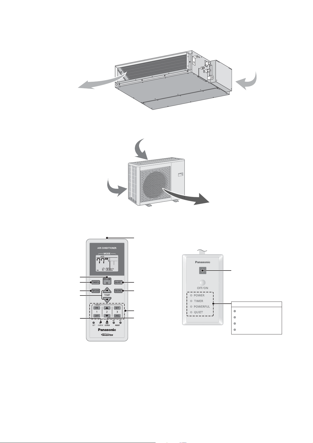
4. Location of Controls and Components
A
A
4.1 Indoor Unit
ir outlet
Air inlet
4.2 Outdoor Unit
ir inlet (side)
4.3 Remote Control
Air inlet (rear)
Air outlet
Transmitter
Remote control receiver
Powerful operation
Temperature setting
OFF/ON
Operation mode
Check
Quiet operation
Fan speed selection
Timer setting
Clock setting
Indicator
POWER
TIMER
POWERFUL
QUIET
(Green)
(Orange)
(Orange)
(Orange)
15

5. Dimensions
5.1 Indoor Unit
<Front View>
145 (5 - 11/16)
(AIR OUTLET DUCT FLANGE)
<Bottom View>
26 (1 - 1/32)
5 - Ø 3.1 HOLE
(AIR OUTLET DUCT FLANGE)
692 (27 - 1/4)
160 X 4 = 640
96 (3 - 25/32)
2 - Ø 3.1 HOLE
27 (1 - 1/16)
WATER INLET
28 (1-3/32)
<Side View>
84 (3-5/16)
81 (3-3/16)
30 (1-3/16)
10 (3/8)
143 (5-5/8)
80 (3-1/8)
238 (9 - 3/8)
44
(1 - 23/32)
640 (25 - 3/16)
564 (22 - 3/16)
<Back View>
(AIR INLET)
126 (4 - 31/32)
AIR FILTER
40
(1-9/16)
23 (1 - 3/32)
155 ( 6 - 3/32)
120 (4 - 23/32)
750 (29 - 17/32)
824 (32 - 7/16)
904 (35 - 9/16)
680 (26 - 25/32)
(AIR INLET)
14 (17/32)
14 (17/32) 14 (17/32)
194 ( 7 - 5/8)
120 (4 - 23/32)33 (1 - 5/16)
DRAIN PORT (UPPER & LOWER)
150 (5 7/8)
200 ( 7- 7/8)
<Remote Control>
59 (2-5/16)
144.5 (5-11/16)
18 (11/16)
<Remote Control Holder>
87 (3-13/32)
23 (7/8)
23 (7/8) 23 (7/8)
14 (17/32)
220 (8 - 21/32) 220 (8 - 21/32)132 (5 - 3/16) 132 (5 - 3/16)
63.68 (2-1/2)
Unit : mm/inch
16
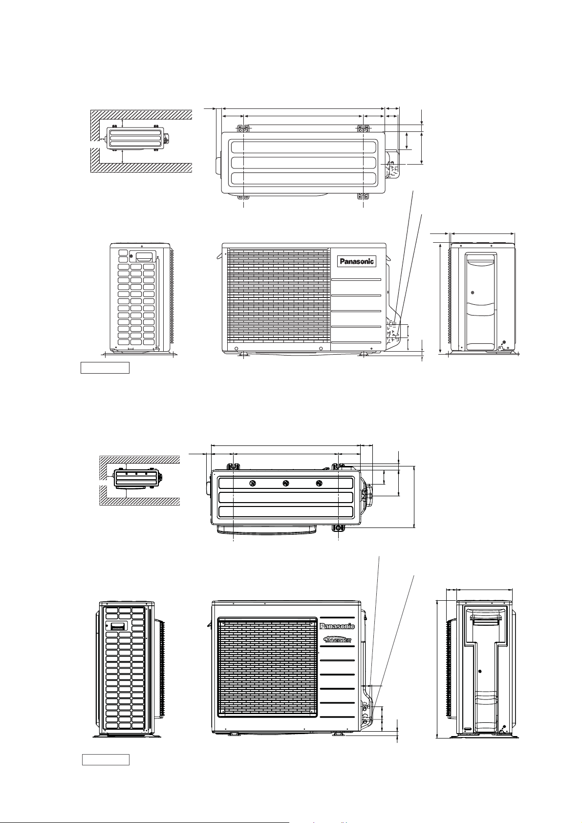
5.2 Outdoor Unit
5.2.1 CU-E9SD3UA CU-E12SD3UA
Space necessary for
installation
10 cm
24.4
(15/16)
<Top View>
(104.7)
(4-3/32)
780 (30-23/32)
570 (22-7/16)
104.9
(4-1/8)
67.6
(2-21/32)
60.5
(2-3/8)
34.5
(1-11/32)
10 cm
100 cm
Anchor Bolt Pitch
320 x 570
Unit : mm/inch
5.2.2 CU-E18SD3UA
Space necessary for
installation
10 cm
10 cm
100 cm
27.5
(1-1/16)
<Front View><Side View>
<Top View>
(131)
(5-5/32)
875 (34-15/32)
613 (24-1/8)
84.8
(3-5/16)
155 (6-3/32)
2-way valve at Liquid side
(High Pressure)
3-way valve at Gas side
(Low Pressure)
<Side View>
289 (11-13/32)
542 (21-11/32)
61.6
69.6
(2-13/32)
(18)
(2-23/32)
11.5 (7/16)
(11/16)
70
(2-3/4)
131
(5-5/32)
82
38
(3-7/32)
152
(1-1/2)
(5-31/32)
Anchor Bolt Pitch
360.5 x 613
Unit: mm/inch
360.5 (14-3/16)
2-way valve at Liquid side
(High Pressure)
3-way valve at Gas side
(Low Pressure)
<Front View><Side View>
64 (2-1/2)
75
(2-15/16)
(25)
(31-32)
70
(2-3/4)
<Side View>
59
(2-5/16)
795 (31-5/16)
320 (12-5/8)
17
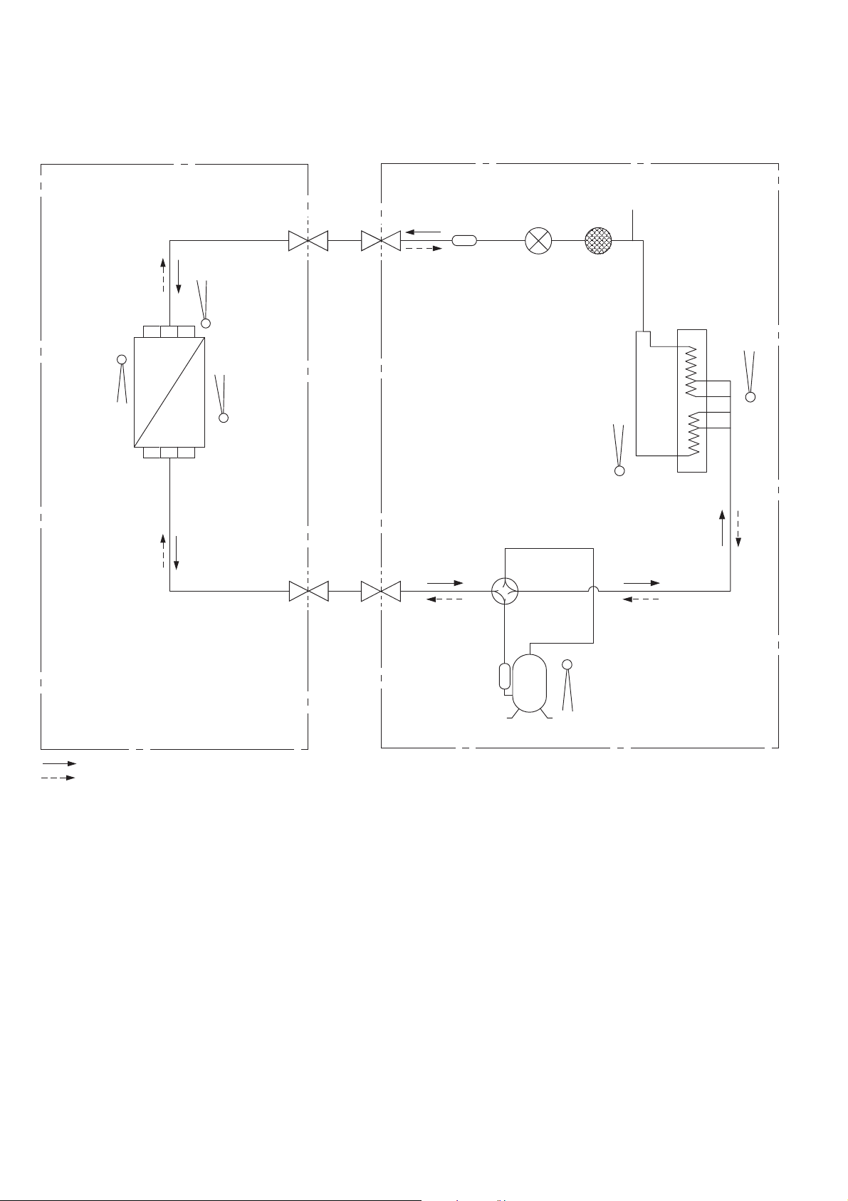
6. Refrigeration Cycle Diagram
6.1 CS-E9SD3UAW CU-E9SD3UA
INDOOR
LIQUID
SIDE
2-WAY
VALV E
INTAKE
TEMP.
SENSOR
HEAT EXCHANGER
(EVAPORATOR)
PIPE
TEMP.
SENSOR 1
PIPE
(INLET)
TEMP.
SENSOR 2
DISCHARGE
MUFFLER
EXPANSION
VALV E
SENSOR
OUTDOOR
PROCESS
TUBE
STRAINER
PIPE
TEMP.
CONDENSER
AIR
TEMP.
SENSOR
COOLING
HEATING
GAS
SIDE
3-WAY
VALV E
4-WAYS VALVE
DISCHARGE
MUFFLER
COMPRESSOR
TEMP. SENSOR
COMPRESSOR
18
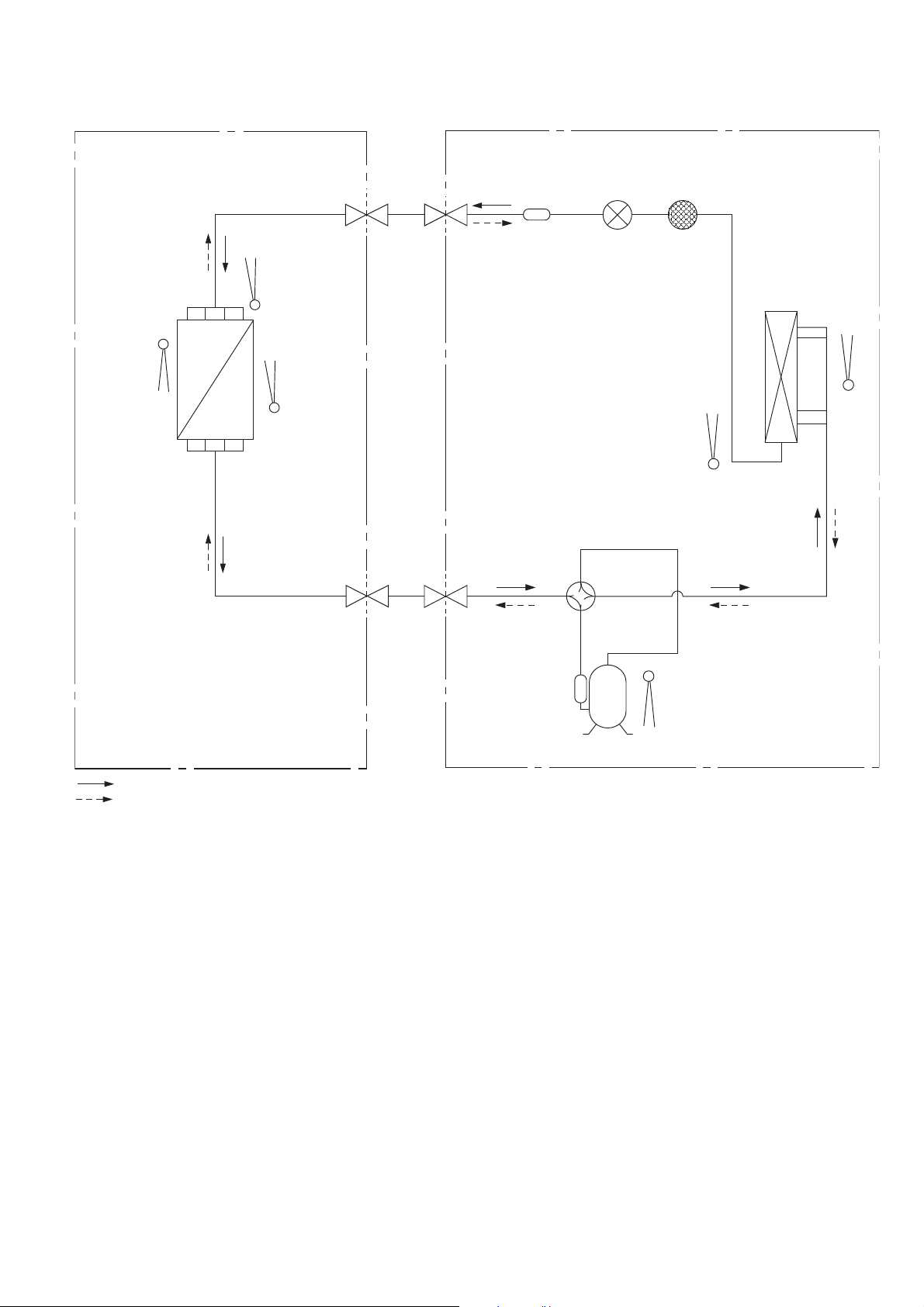
6.2 CS-E12SD3UAW CU-E12SD3UA
INDOOR
OUTDOOR
INTAKE
TEMP.
SENSOR
HEAT EXCHANGER
(EVAPORATOR)
PIPE
TEMP.
SENSOR 1
PIPE
(INLET)
TEMP.
SENSOR 2
LIQUID
SIDE
2-WAY
VALV E
GAS
SIDE
3-WAY
VALV E
DISCHARGE
MUFFLER
4-WAYS VALVE
EXPANSION
VALV E
STRAINER
PIPE
TEMP.
SENSOR
CONDENSER
AIR
TEMP.
SENSOR
COOLING
HEATING
DISCHARGE
MUFFLER
COMPRESSOR
TEMP. SENSOR
COMPRESSOR
19
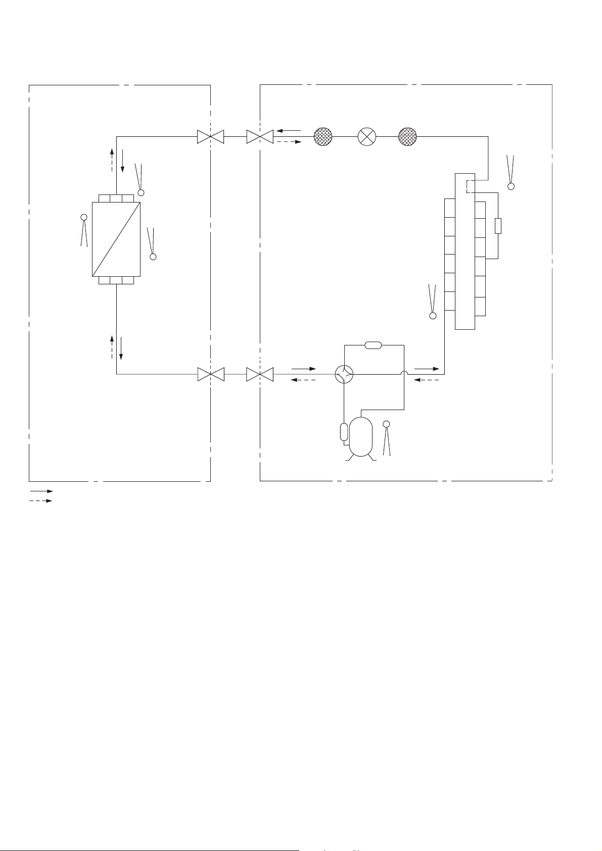
6.3 CS-E18SD3UAW CU-E18SD3UA
INDOOR
OUTDOOR
INTAKE
TEMP.
SENSOR
HEAT EXCHANGER
(EVAPORATOR)
PIPE
TEMP.
SENSOR 1
PIPE
(INLET)
TEMP.
SENSOR 2
LIQUID
SIDE
2-WAY
VALV E
GAS
SIDE
3-WAY
VALV E
4-WAYS VALVE
EXPANSION
VALV E
DISCHARGE
MUFFLER
STRAINERRECEIVER
PIPE
TEMP.
SENSOR
AIR
TEMP.
SENSOR
DISTRIBUTOR
COOLING
HEATING
COMPRESSOR
TEMP. SENSOR
COMPRESSOR
20
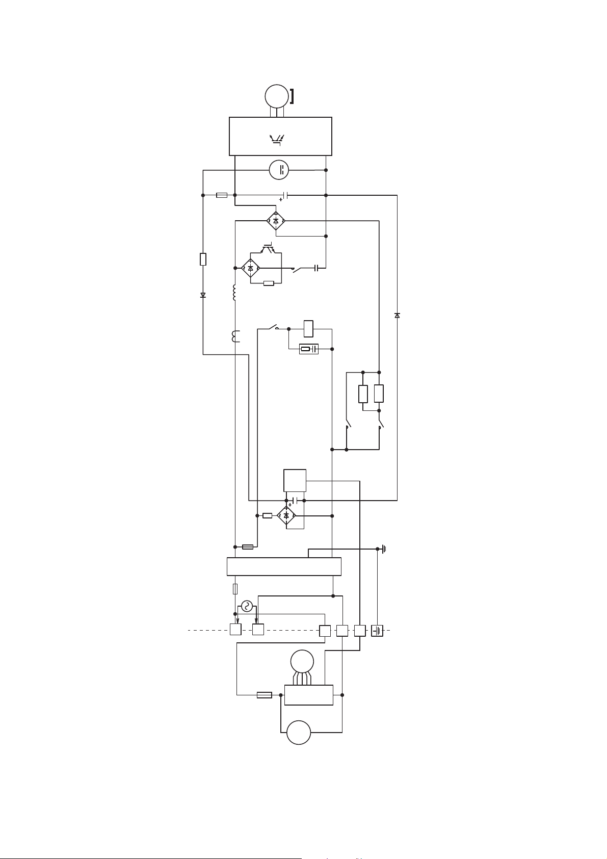
7. Block Diagram
7.1 CS-E9SD3UAW CU-E9SD3UA CS-E12SD3UAW CU-E12SD3UA
3 ~
MS
COMPRESSOR
Q1
PTC
PTC2
REACTOR
PTC
PTC1
DB101
DB102
NTC
TH2
M
EXPANSION
VALV E
DB103
FUSE103
FAN MOTOR
M
C101
RY-C
SC
U
4-WAYS
VALV E
RY-AC1
RY-PWR
FUSE102
FUSE101
1
Indoor Unit Outdoor Unit
SINGLE
PHASE
POWER
FUSE
SUPPLY
21
NOISE FILTER
60Hz
1 Ø 208/230V
FM
SC
DM
CT102
2
3
7.2 CS-E18SD3UAW CU-E18SD3UA
3 ~
MS
U
V
W
COMPRESSOR
NTC
TH2
FUSE1
REACTOR
CT400
P
M
DB3
Q1
DB1
RY-HOT
N
RY-C
4-WAYS VALVE
CR3
PTC1
RY-PWR2
PTC2
RY-AC
FUSE2
FUSE3
SINGLE PHASE
POWER SUPPLY
AC208 - 230V
60Hz
L1
Indoor Unit Outdoor Unit
L2
TH1
NTC
FUSE
DB2
SC
NOISE FILTER
2
1
3
FM
SC
DM
22
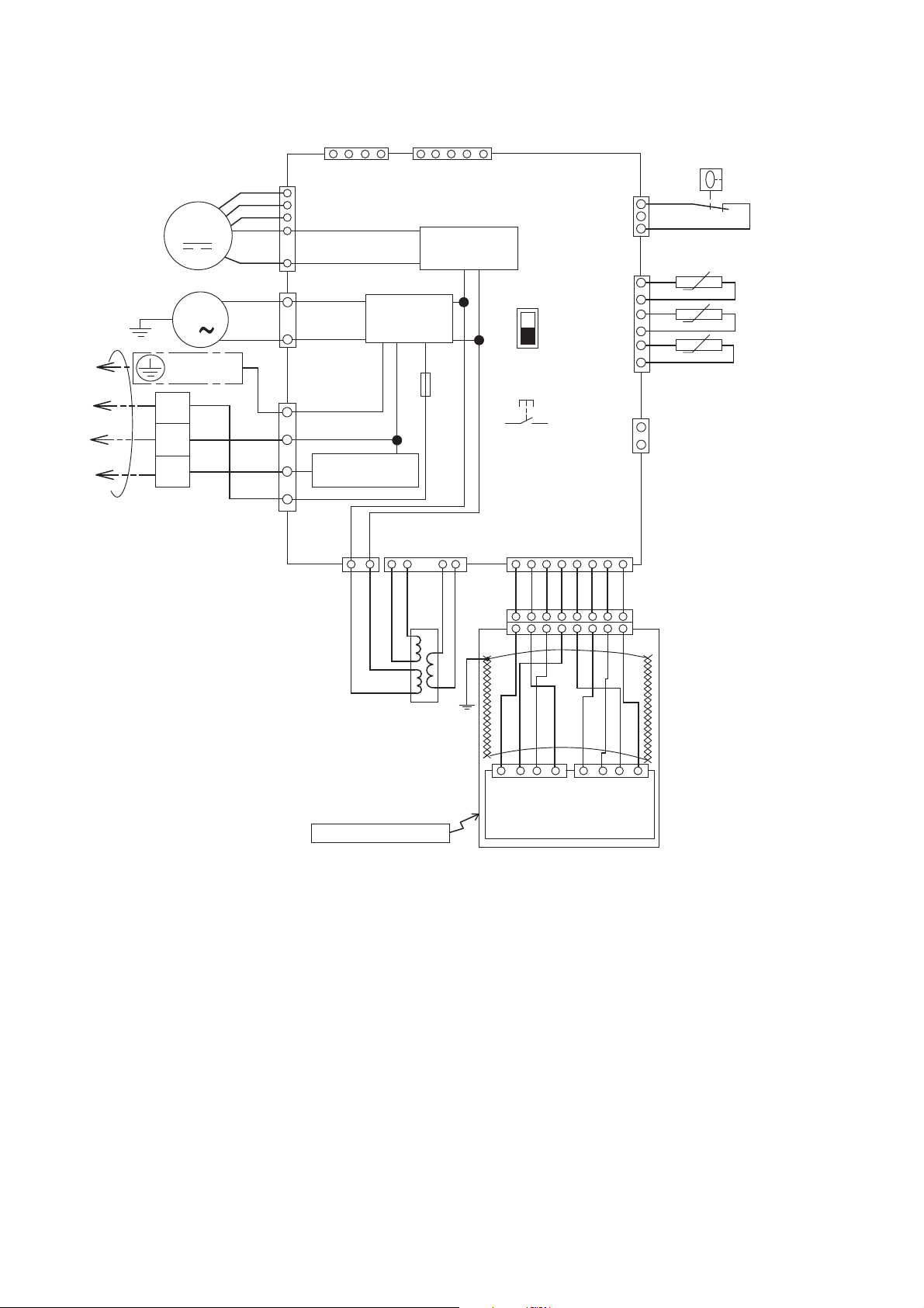
8. Wiring Connection Diagram
8.1 Indoor Unit
DRAIN PUMP
Y/G
GROUNDING
TERMINAL
1
2
TO OUTDOOR UNIT
3
TERMINAL
BOARD
MOTOR
M
M
1
BL
W
R
Y
B
W
BL
R
Y
Y
G
141
HAJEM-A
(WHITE)
7
CN-FM
6
(WHITE)
5
4
1
3
CN-DRMTR1
(BLUE)
1
1
CN-AC (WHITE)
3
5
COMMUNICATION
NOISE FILTER
CIRCUIT
CIRCUIT
7
CN-T1
(BLUE)
4
BL BL
CN-T2 (WHITE)
6
1 1 2 3 4
O O R R
CN-CNT
(WHITE)
RECTIFICATION
CIRCUIT
FUSE
T3.15A L250V
2
5
5
ELECTRONIC
CONTROLLER
SW2
SW1
DRAIN TEST
1
G
CN-DISP (WHITE)
BR R O Y P B V GR
1 2 3 4 5 6 7 8
BL
1 2 3 4
CN-FSW
(GREEN)
CN-TH
(WHITE)
CN-HT
(WHITE)
5 6 7 8
5 6 7 8
BL
1
3
BL
BL
6
BL
t˚
BL
BL
t˚
BL
BL
1
2
1
t˚
BL
FLOAT
SWITCH
INDOOR PIPE TEMPERATURE
SENSOR 2
INDOOR PIPE TEMPERATURE
SENSOR 1
INDOOR AIR TEMPERATURE
SENSOR
REMARKS
B: BLUE P:PINK
BR: BROWN O: ORANGE
BL: BLACK Y: YELLOW
W: WHITE GR: GRAY
R: RED G: GREEN
V: VIOLET Y/G: YELLOW/GREEN
TRANSFORMER
REMOTE CONTROLLER
BL
YBR GRRO VW
1 2 3 4 1 2 3 4
CN-DISP2
(WHITE)
CN-DISP1
(YELLOW)
DISPLAY & RECEIVER
23
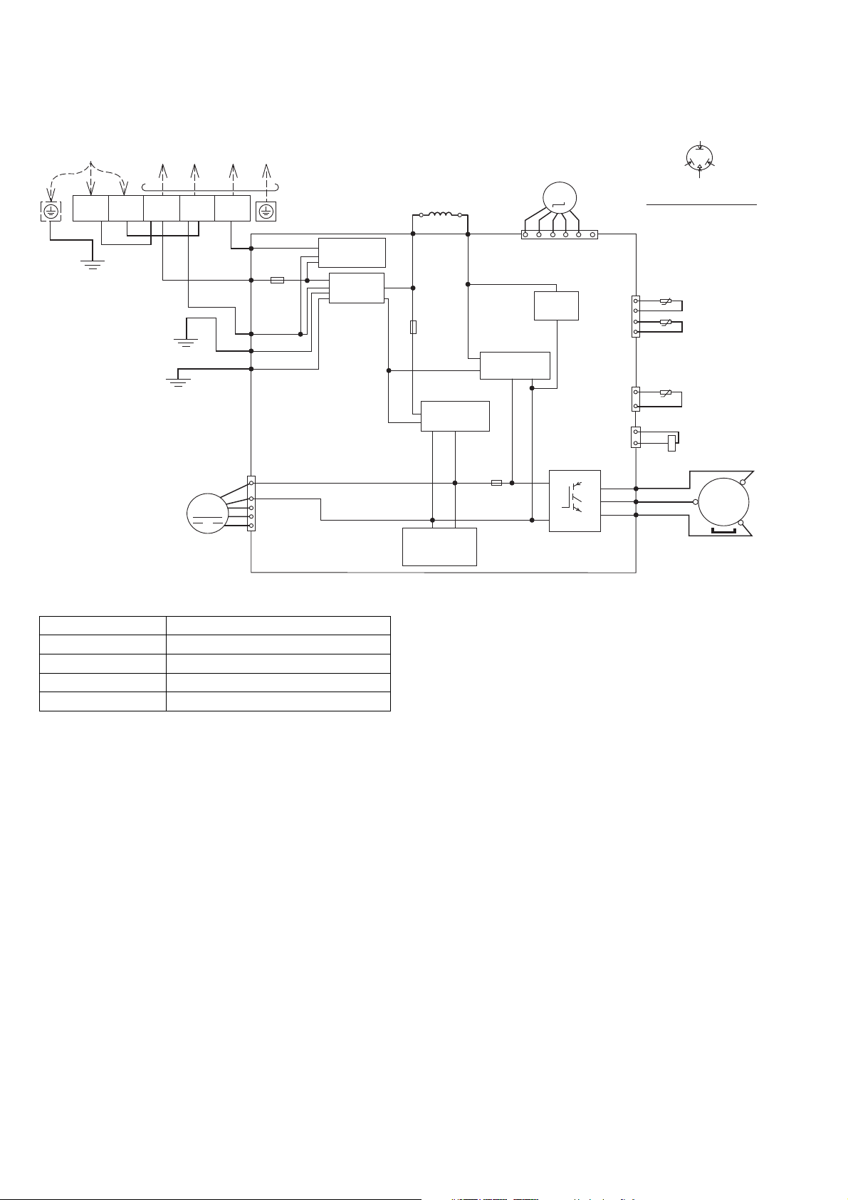
8.2 Outdoor Unit
8.2.1 CU-E9SD3UA CU-E12SD3UA
SINGLE PHASE
POWER SUPPLY
L2
L1
YLW/GRN
REMARKS
BLK: BLACK
BLU: BLUE
WHT: WHITE
RED : RED
YLW : YELLOW
GRY : GRAY
GRN: GREEN
BRW: BROWN
ORG: ORANGE
YLW/GRN: YELLOW/GREEN
BLK
TO INDOOR UNIT
1
(BLACK)2(WHITE)
BLK
WHT
GRN
MOTOR
WHT
GRN
FAN
M
3
(RED)
RED
TERMINAL BOARD
DATA (RED)
AC-BLK
(BLK)
FUSE101
20A 250V
AC-WHT
(WHT)
FG1 (GRN)
LJP101 (GRN)
1
4
CN-DCFM
(WHT)
7
COMMUNICATION
CIRCUIT
NOISE FILTER
CIRCUIT
REACTOR
GRY GRY
RAT2
(GRY)
FUSE102
RECTIFICATION
SWITCHING
POWER SUPPLY
CIRCUIT
RAT1
(GRY)
T3.15A L250V
CIRCUIT
T3.15A L250V
ELECTRO-MAGNETIC
COIL (EXPANSION VALVE)
M
1
RECTIFICATION
CIRCUIT
FUSE103
CN-STM
(WHT)
CIRCUIT
PFC
P
N
6
CN-TANK
(WHT)
CN-HOT
(WHT)
Q1
CN-TH
(WHT)
U
V
W
ELECTRONIC CONTROLLER
(RED)
(BLU)
(YLW)
1
2
3
4
1
3
1
2
Resistance of Compressor Windings
MODEL CU-E9SD3UA/CU-E12SD3UA
CONNECTION 5RS102XHA21
U-V 1.741 Ω
U-W 1.765 Ω
V-W 1.711 Ω
Note: Resistance at 68°F of ambient temperature.
YELLOW (YEL)
BLUE (BLU)
(TRADEMARK)
COMPRESSOR TERMINAL
THE PARENTHESIZED LETTERS IS
INDICATED ON TERMINAL COVER
AIR TEMP. SENSOR
(THERMISTOR)
t˚
t˚
PIPING TEMP. SENSOR
(THERMISTOR)
COMPRESSOR TEMP. SENSOR
(THERMISTOR)
t˚
YLW
YLW
RED
BLU
YLW
RED (RED)
ELECTRO-MAGNETIC
COIL (4-WAY VALVE)
MS
3~
COMPRESSOR
24
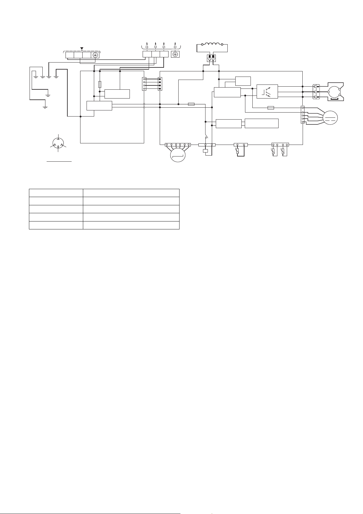
8.2.2 CU-E18SD3UA
SINGLE PHASE POWER SUPPLY
BLK
CIRCUIT
COM3
(RED)
TERMINAL
BOARD
CN-COM
(YELLOW)
CN-BLK
(BLACK)
CN-WHT
(WHITE)
GRN
L1 L2
RED
(RED)
YLW/GRN
GRN
YLW/GRN
YELLOW (YEL)
BLUE
(BLU)
(TRADEMARK)
COMP. TERMINAL
THE PARENTHESIZED LETTERS IS
INDICATED ON THE TERMINAL COVER
WHT
ACN1
(WHITE)
NOISE FILTER
CIRCUIT
FG1 (GREEN)
ELECTRONIC CONTROLLER
(NOISE FILTER)
TERMINAL
BOARD
WHT
BLK
ACL1
(BLACK)
FUSE3
(25A, 250V)
COMMUNICATION
Resistance of Compressor Windings
MODEL CU-E18SD3UA
CONNECTION 5KD240XAF21
U-V 0.720 Ω
U-W 0.726 Ω
V-W 0.708 Ω
Note: Resistance at 68°F of ambient temperature.
1
WHT
1
WHT
WHT
WHT
4
WHT
TO INDOOR UNIT
23
RED
1
CN-COM
(YELLOW)
4
AC-BLK
(BLACK)
BLK
AC-WHT
(WHITE)
6
ELECTRO-MAGNETIC COIL
(EXPANSION VALVE)
(T3.15A L250V)
CN-EV
(WHITE)
M
REACTOR
GRY
2
GRY
L2-1
(GRAY)
FUSE2
RY-HOT
1
1
ELECTRO-MAGNETIC
COIL (4-WAY VALVE)
1
12
BLK
L2-0
(BLACK)
RECTIFICATION
CIRCUIT
RECTIFICATION
CIRCUIT
CN-HOT
(BLUE)
BLK
PFC
CIRCUIT
CN-TANK
(WHITE)
33
t˚
COMP. TEMP.
SENSOR
(THERMISTOR)
ELECTRONIC CONTROLLER (MAIN)
Q10
P
N
FUSE1
(T3.15A L250V)
SWITCHING POWER
SUPPLY CIRCUIT
1
PIPING TEMP.
SENSOR
(THERMISTOR)
(RED)
U
(BLUE)
V
(YELLOW)
W
(WHITE)
CN-TH1
(WHITE)
41
t˚ t˚
OUTDOOR AIR
TEMP. SENSOR
(THERMISTOR)
REMARKS
BLU: BLUE BRW: BROWN
ORG: ORANGE BLK: BLACK
YLW: YELLOW WHT: WHITE
GRY: GRAY RED: RED
GRN: GREEN
YLW/GRN: YELLOW/GREEN
COMPRESSOR
3
RED
BLU
YLW
RED
BLK
WHT
BLU
YLW
11
3
RED
BLU
YLW
FAN MOTOR
CN-FM
U
V
W
1
4
7
MS
3
~
M
25
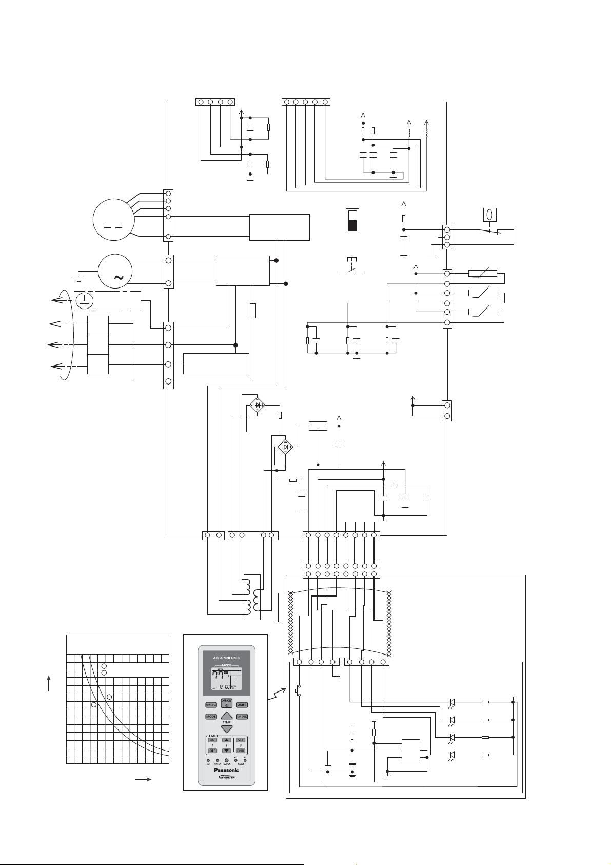
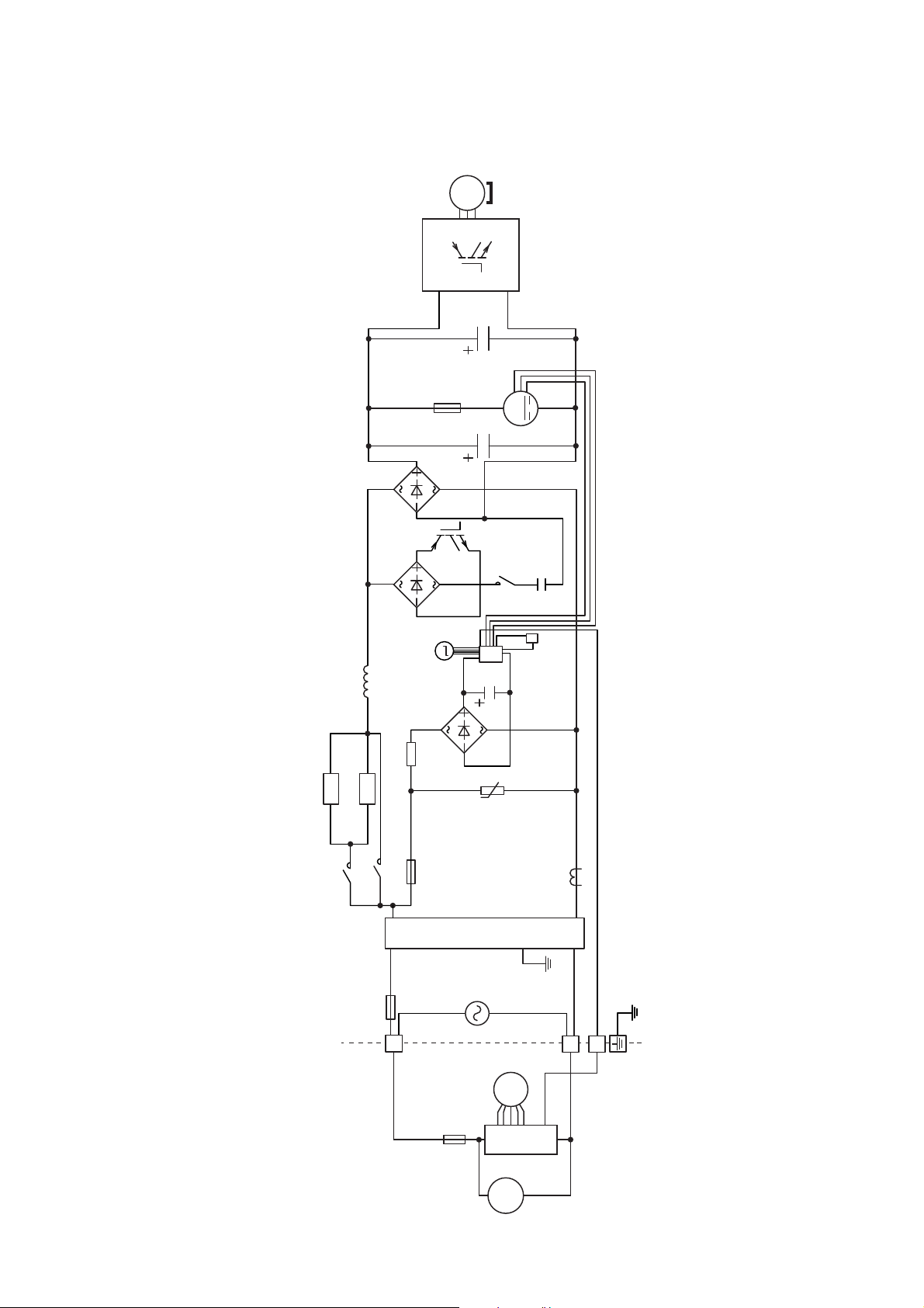
9. Electronic Circuit Diagram
9.1 Indoor Unit
5V
NOISE FILTER
CIRCUIT
FUSE
S1WB(A)60
6
1 1 2 3 4
5
O O R R
DRAIN PUMP
Y/G
GROUNDING
TERMINAL
1
2
TO OUTDOOR UNIT
3
TERMINAL
BOARD
MOTOR
M
M
1
BL
W
14
HAJEM-A
(WHITE)
Y
7
B
W
BL
R
Y
Y
R
G
CN-FM
6
(WHITE)
5
4
1
3
CN-DRMTR1
(BLUE)
1
1
CN-AC (WHITE)
3
5
COMMUNICATION
CIRCUIT
7
CN-T1
4
(BLUE)
BL BL
1
KB
R20
C32
10k
0.01u
KB
R56
C38
10k
0.01u
RECTIFICATION
CIRCUIT
T3.15A L250V
15.0k
R74
22k
DB3
1/4W
S1WB(A)60
R75
5.1k
KB
C46
0.1u
25V
CN-T2
(WHITE)
2
1
BL
G
CN-CNT
(WHITE)
1000p
R90
10k
KB
C52
50V
5V
5
SW2
SW1
DRAIN TEST
R62
1%
KB
C30
1u
10V
R63
20.0k
1%
KB
C31
1u
10V
ELECTRONIC
CONTROLLER
IC5
NJM7812FA
DB2
BR R O Y P B V GR
1 2 3 4 5 6 7 8
1 2 3 4
12V
i
o
12V
g
C8
NONE
CN-DISP
(WHITE)
5 6 7 8
5 6 7 8
R82
10k
C66
1000p
50V
R89
20.0k
1%
KB
12V
5V
L6
L5
C56
5V
CN-FSW
R65
(GREEN)
KB
C51
1u
10V
10k
1000p
KB
C35
50V
5V
CN-TH
(WHITE)
12V
1
3
CN-HT
(WHITE)
2
BL
FLOAT
SWITCH
BL
6
BL
BL
t˚
BL
BL
t˚
BL
BL
1
t˚
INDOOR PIPE
TEMPERATURE
SENSOR 2
INDOOR PIPE
TEMPERATURE
SENSOR 1
INDOOR AIR
TEMPERATURE
SENSOR
1
5V
R32
10k
KB
C17
0.01u
KB
C22
3300p
C34
0.1u
16V
KB
BL
70
60
50
40
30
Resistance (kΩ)
20
10
0
14 32 50
Sensor (Thermistor)
Characteristics
1
Pipe Temp. Sensor
2
Intake Air Temp. Sensor
1
2
68 86 104 122
o
Temperature (
F)
TRANSFORMER
REMOTE CONTROLLER
BL
YBR GRRO VW
1 2 3 4 1 2 3 4
SW201
5V
CN-DISP2
(WHITE)
C202
0.1uF
5V
R202
47
C201
+
47uF
6.3V
26
5V
R201
10k
CN-DISP1
(YELLOW)
IC201
GP1UM262RK
VOUT
1
VCC
235
GND
DISPLAY & RECEIVER
LED202
POWER GREEN
LED203
TIMER ORANGE
LED204
POWERFUL ORANGE
LED205
4
QUIET ORANGE
R2 0
R3 0
R4 0
R5 0
5V
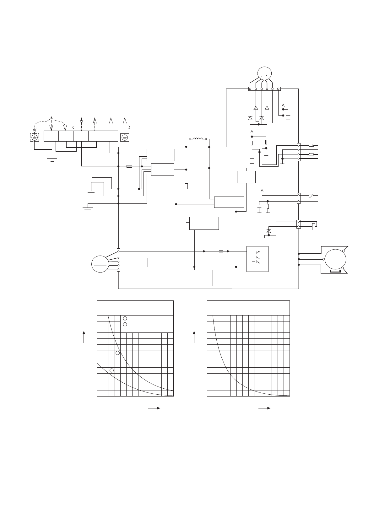
9.2 Outdoor Unit
9.2.1 CU-E9SD3UA CU-E12SD3UA
SINGLE PHASE
POWER SUPPLY
L1
YLW/GRN
L2
BLK
TO INDOOR UNIT
1
(BLACK)2(WHITE)
WHT
BLK
GRN
WHT
FAN
MOTOR
GRN
M
3
(RED)
RED
TERMINAL BOARD
DATA (RED)
AC-BLK
(BLK)
FUSE101
20A 250V
AC-WHT
(WHT)
FG1 (GRN)
LJP101 (GRN)
1
4
CN-DCFM
(WHT)
7
COMMUNICATION
CIRCUIT
NOISE FILTER
CIRCUIT
REACTOR
GRY
RAT2
(GRY)
FUSE102
RECTIFICATION
SWITCHING
POWER SUPPLY
CIRCUIT
GRY
RAT1
(GRY)
T3.15A L250V
RECTIFICATION
CIRCUIT
FUSE103
T3.15A L250V
ELECTRO-MAGNETIC
COIL (EXPANSION VALVE)
M
CN-STM
16
(WHT)
D28
D27
D29
5V
G2
R11
15.8k
1%
C6
1u
KB
CIRCUIT
10V
PFC
CIRCUIT
G2
G2
5V
C3
1u
KB
10V
G2
G2
D9
G2
Q1
P
U
V
W
N
ELECTRONIC CONTROLLER
D26
R12
15.0k
1%
C7
1u
KB
10V
4.99k
R1
1%
(RED)
(BLU)
(YLW)
13V
G2
CN-TH
(WHT)
G2
CN-TANK
(WHT)
CN-HOT
(WHT)
C80
AIR TEMP. SENSOR
(THERMISTOR)
t˚
1
2
t˚
3
4
PIPING TEMP. SENSOR
(THERMISTOR)
1
t˚
3
1
YLW
2
YLW
RED
BLU
YLW
COMPRESSOR
TEMP. SENSOR
(THERMISTOR)
ELECTRO-MAGNETIC
COIL (4-WAY VALVE)
MS
3~
COMPRESSOR
70
60
50
40
30
0
14 32 50
2
Resistance (kΩ)
20
10
Sensor (Thermistor)
Characteristics
1
Outdoor Air Sensor
2
Outdoor Heat Exchanger
Sensor
1
68 86 104 122
o
Temperature (
F)
Compressor Temp. Sensor
(Thermistor) Characteristics
70
60
50
40
30
Resistance (kΩ)
20
10
0
68 104 140
Temperature (
176 212 248 284
o
F)
27
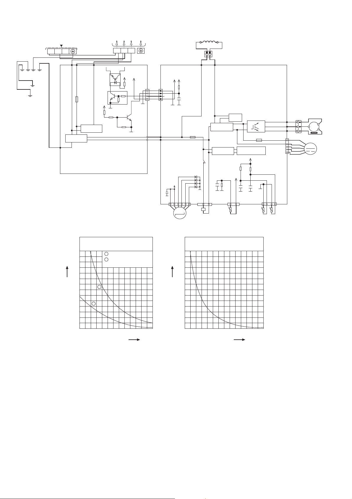
9.2.2 CU-E18SD3UA
SINGLE PHASE POWER SUPPLY
TERMINAL
BLK
WHT
COM3
(RED)
PC8
EL816X
(X)
Q25
0.1A
50V
RT1N432C
5V
R425
20.0k
1/10W
CIRCUIT
ELECTRONIC CONTROLLER
(NOISE FILTER)
BOARD
GRN
YLW/GRN
YLW/GRN
GRN
L1 L2
WHT
ACN1
(WHITE)
NOISE FILTER
FG1 (GREEN)
CIRCUIT
TERMINAL
BOARD
BLK
ACL1
(BLACK)
FUSE3
(25A, 250V)
COMMUNICATION
G1
R426
5.6k
1/10W
3
2
c
e
TO INDOOR UNIT
1
23
RED
4
5V
R422
680
1
1/10W
4.7k
b
10k
Q26
b
0.2A
50V
2SC3052
R427
47k
1/10W
5V
c
e
G1
CN-COM
(YELLOW)
G1
CN-BLK
(BLACK)
CN-WHT
(WHITE)
REACTOR
1
12
BLK
L2-0
(BLACK)
RECTIFICATION
CIRCUIT
RECTIFICATION
CIRCUIT
KB
C49
1u
6.3V
G5
G5
CN-HOT
(BLUE)
BLK
ELECTRONIC CONTROLLER (MAIN)
PFC
Q10
CIRCUIT
R410
4.99k
1/10W
1%
33
t˚
COMP. TEMP.
SENSOR
(THERMISTOR)
P
N
(T3.15A L250V)
SWITCHING POWER
SUPPLY CIRCUIT
5V
R101
15.8k
1/10W
1%
5V
KB
C46
1u
6.3V
G5
G5
CN-TANK
(WHITE)
1
FUSE1
R100
15.0k
1/10W
1%
KB
C45
1u
6.3V
PIPING TEMP.
(THERMISTOR)
(RED)
U
V
W
G5
41
t˚ t˚
SENSOR
U
V
(BLUE)
(YELLOW)
CN-FM
(WHITE)
CN-TH1
(WHITE)
OUTDOOR AIR
TEMP. SENSOR
(THERMISTOR)
COMPRESSOR
3
3
RED
RED
BLU
BLU
MS
3
YLW
FAN MOTOR
M
~
YLW
W
11
1
RED
4
BLK
WHT
BLU
7
YLW
GRY
2
GRY
L2-1
(GRAY)
5V
5V
CN-COM
(YELLOW)
1
WHT
WHT
WHT
WHT
4
AC-BLK
(BLACK)
BLK
WHT
AC-WHT
(WHITE)
C84
R159
1
4
10k
KB
C63
1000p
50V
G5
G6
(T3.15A L250V)
13V
G2
M
ELECTRO-MAGNETIC COIL
(EXPANSION VALVE)
FUSE2
RY-HOT
D33
D34
D35
D36
G2
CN-EV
(WHITE)
116
ELECTRO-MAGNETIC
COIL (4-WAY VALVE)
70
60
50
40
30
Resistance (kΩ)
20
2
10
0
14 32 50
Sensor (Thermistor)
Characteristics
1
Outdoor Air Sensor
2
Outdoor Heat Exchanger
Sensor
1
68 86 104 122
Temperature (
o
F)
70
60
50
40
30
Resistance (kΩ)
20
10
0
68 104 140
Compressor Temp. Sensor
(Thermistor) Characteristics
176 212 248 284
Temperature (
o
F)
28
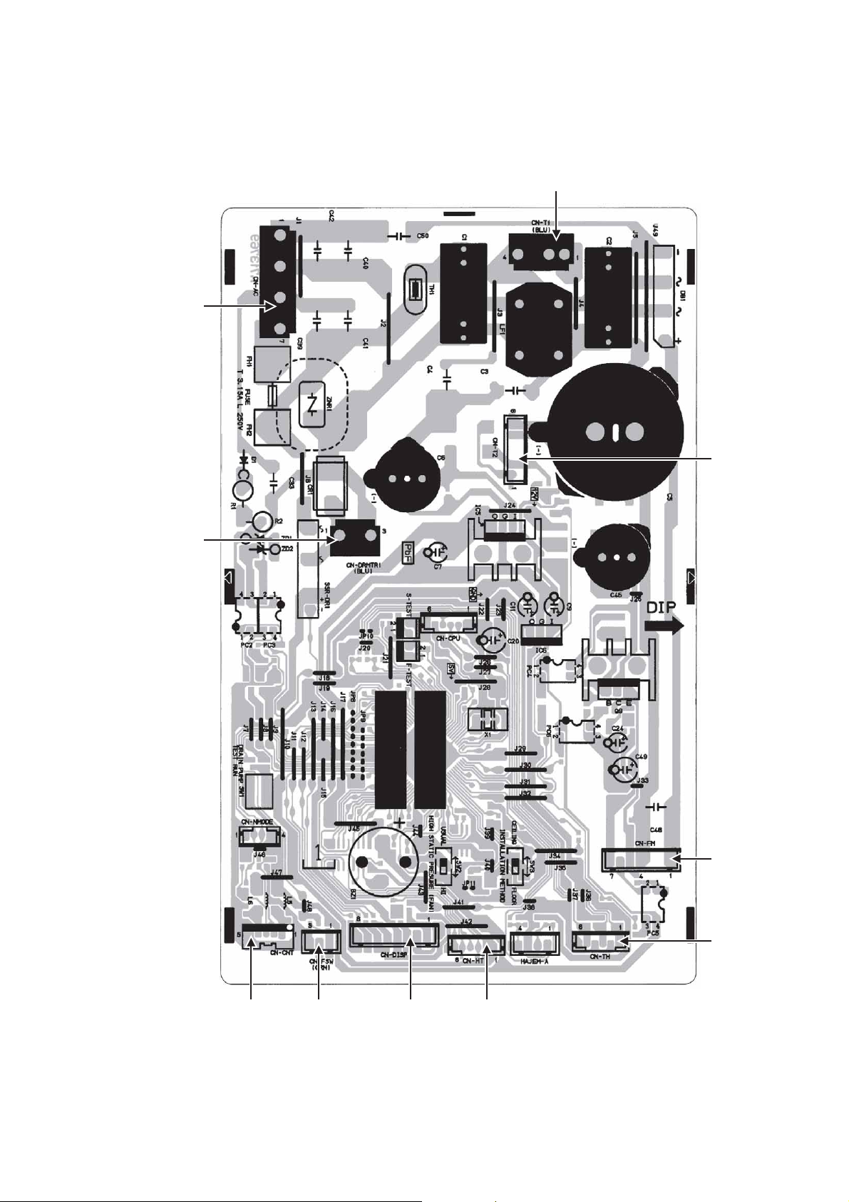
10. Printed Circuit Board
10.1 Indoor Unit
10.1.1 Main Printed Circuit Board
CN-AC
CN-T1
CN-T2
CN-DRMTR1
CN-FM
CN-TH
CN-DISP CN-HTCN-FSWCN-CNT
29
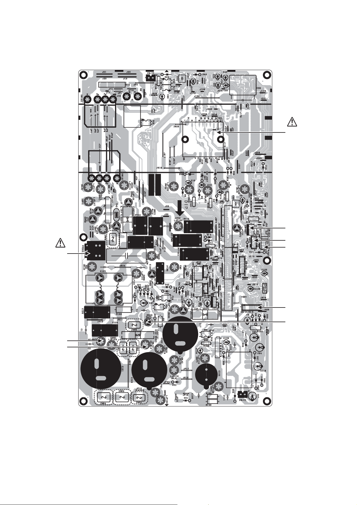
10.2 Outdoor Unit
10.2.1 Main Printed Circuit Board
10.2.1.1 CU-E9SD3UA CU-E12SD3UA
POWER
TRANSISTOR
(IPM)
CURRENT
TRANSFORMER
(CT)
AC-WHT
AC-BLK
CN-HOT
CN-TH
CN-TANK
CN-DCFM
DATA
30
 Loading...