

Page 1
Order No. MAC0706002A2
Air Conditioner
CS-CE7GKEW CU-CE7GKE
CS-CE9GKEW CU-CE9GKE
CS-CE12GKEW CU-CE12GKE
Please file and use this manual together with the service manual for Model No. CS-E9GKEW-5 / CUE9GKE-5, CS-E12GKEW-5 / CU-E12GKE-5, Order No. MAC0612063C2.
TABLE OF CONTENTS
PAGE PAGE
1 Specifications -----------------------------------------------------2
1.1. CS-CE7GKEW CU-CE7GKE--------------------------2
1.2. CS-CE9GKEW CU-CE9GKE--------------------------4
1.3. CS-CE12GKEW CU-CE12GKE----------------------- 6
2 Technical Dat a----------------------------------------------------- 8
2.1. Operation Characteristics--------------------------------8
2.2. Sensible Capacity Chart--------------------------------20
3 Exploded View and Replacement Parts List-----------21
3.1. Indoor Unit------------------------------------------------- 21
3.2. Outdoor Unit----------------------------------------------- 23
©
2007 Panasonic HA Air-Conditioning (M) Sdn. Bhd.
(11969-T). All rights reserved. Unauthorized copying
and distribution is a violation of law.
Page 2
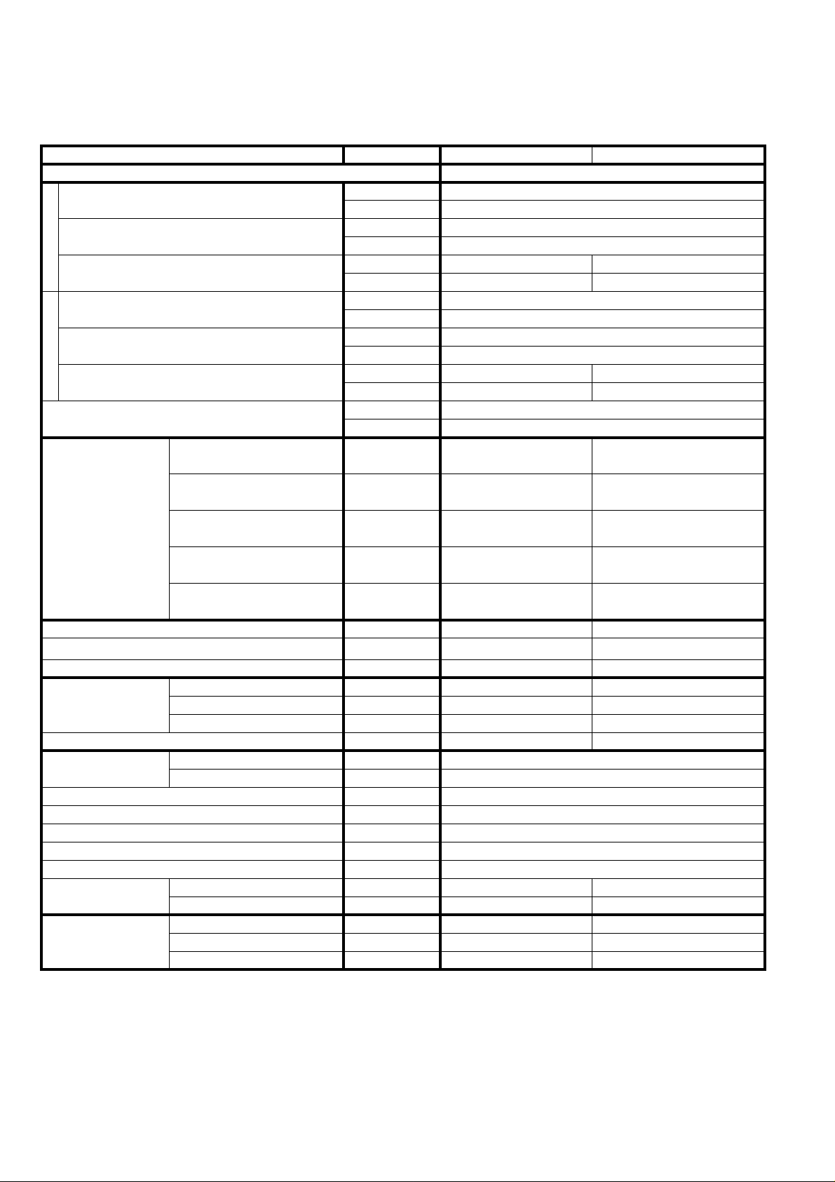
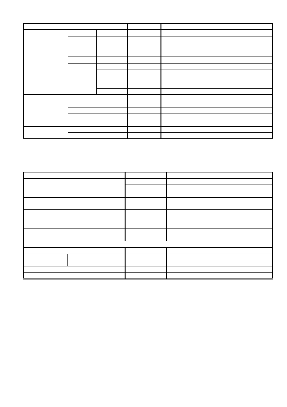
1 Specifications
1.1. CS-CE7GKEW CU-CE7GKE
ITEM UNIT INDOOR UNIT OUTDOOR UNIT
Performance Test Condition EUROVENT
C
Capacity
O
O
EER
L
I
N
Noise Level
G
H
Capacity
E
A
COP
T
I
N
Noise Level
G
Moisture Removal
Q-Lo
Lo
Air Volume
Refrigeration Control Device — Check Valve & Capillary Tube
Refrigeration Oil
Refrigerant (R410A) g (oz) — 790 (27.9)
Dimension
Net Weight kg (lbs) 9 (20) 33 (73)
Pipe Diameter
Standard Length m (ft) 7.5 (24.6)
Pipe Length Range m (ft) 3 (9.8) ~ 15 (49.2)
Height Difference m (ft) 15 (49.2)
Additional Gas Amount g/m (oz/ft) 20 (0.2)
Refrigeration Charge Less m (ft) 7.5 (24.6)
Drain Hose
Compressor
Me
Hi
SHi
Height mm (inch) 280 (11-1/32) 540 (21-1/4)
Width mm (inch) 799 (31-15/32) 780 (30-23/32)
Depth mm (inch) 183 (7-7/32) 289 (11-3/8)
Gas mm (inch) 9.52 (3/8)
Liquid mm (inch) 6.35 (1/4)
Inner Diameter mm 16 —
Length mm 650 —
Type — Hermetic Motor
Motor Type — Brushless (6-pole)
Rated Output W — 650
kW 2.05 (0.70 ~ 2.40)
kCal/h 1760 (600 ~ 2060)
W/W 4.27 (4.12 ~ 4.07)
kCal/hW 3.67 (3.53 ~ 3.49)
dB (A) High 37, Low 24, Q-Lo 21 High 45
Power level dB High 48, Low 35, Q-Lo 32 58
kW 2.80 (0.70 ~ 4.00)
kCal/h 2410 (600 ~ 3440)
W/W 4.31 (4.38 ~ 3.92)
kCal/hW 3.71 (3.75 ~ 3.37)
dB (A) High 38, Low 25, Q-Lo 22 High 46
Power level dB High 49, Low 36, Q-Lo 33 59
l/h 1.3
pt/h 2.7
3
m
/min (ft3/min)
3
m
/min (ft3/min)
3
m
/min (ft3/min)
3
m
/min (ft3/min)
3
m
/min (ft3/min)
cm
3
Cooling; 4.6 (160)
Heating; 5.1 (180)
Cooling; 6.3 (220)
Heating; 6.5 (230)
Cooling; 7.2 (250)
Heating; 7.7 (270)
Cooling; 9.8 (350)
Heating; 10.3 (360)
Cooling; 10.1 (360)
Heating; 10.7 (380)
— RB68A or Freol Alpha68M (320)
Cooling; 28.8 (1020)
—
—
—
—
2
Page 3
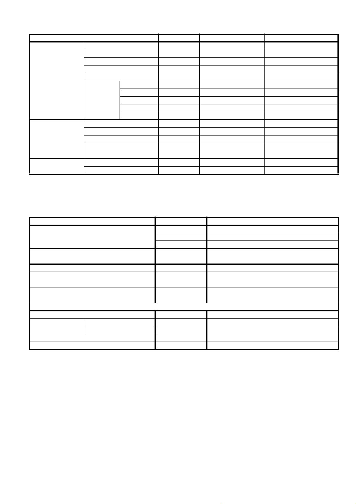
ITEM UNIT INDOOR UNIT OUTDOOR UNIT
Type Cross-Flow Fan Propeller Fan
Material ASG20K1 PP
Motor Type Transistor (8-pole) Induction (6-pole)
Input Power W — 62
Fan
Heat Exchanger
Air Filter
Output Power W 30 25
Q-Lo (Cool/Heat) rpm 740 / 790 —
Lo (Cool/Heat) rpm 790 / 840 —
Fan Speed
Fin Material Aluminium (Pre Coat) Aluminium
Fin Type Slit Fin Corrugated Fin
Row x Stage x FPI 2 x 15 x 19 2 x 24 x 17
Size (W x H x L) mm 610 x 315 x 25.4
Material Polypropelene —
Type One-Touch —
Me (Cool/Heat) rpm 1010 / 1070 —
Hi (Cool/Heat) rpm 1230 / 1300 750 / SHi (Cool/Heat) rpm 1270 /1340 —
36.4 x 504 x 713
684
1. Cooling capacities are based on indoor temperature of 27°C D.B. (80.6°F D.B.), 19.0°C W.B. (66.2°F W.B.) and outdoor air
temperature of 35°C D.B. (95°F D.B.), 24°C W .B. (75.2°F W.B.)
2. Heating capacities are based on indoor temperature of 20°C D.B. (68°F D.B.) and out door air temperature of 7°C D.B. (44.6°F
D.B.), 6°C W.B. (42.8°F W.B.)
Item Unit
ø Single
Power Source (Phase, Voltage, Cycle)
Input Power W
Starting Current A 3.1
Running Current A
Power Factor %
Power factor means total figure of compressor, indoor fan motor and outdoor fan motor.
*Maximum over current protection A 4.8
Power Cord
Thermostat Electronic Control
Protection Device Electronic Control
Number of core —
Length m —
V 230
Hz 50
Cooling; 480 (170 ~ 590)
Heating; 650 (160 ~ 1020)
Cooling; 2.3
Heating; 3.1
Cooling; 91
Heating; 91
Note
• Specifications are subject to change without notice for further improvement.
3
Page 4
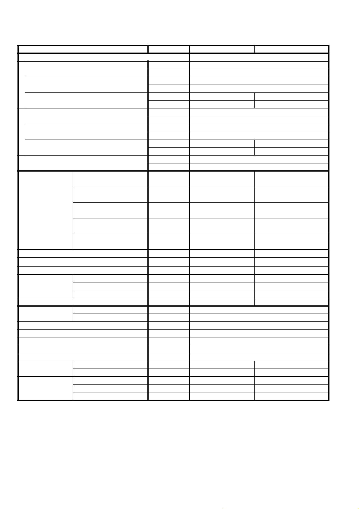
1.2. CS-CE9GKEW CU-CE9GKE
ITEM UNIT INDOOR UNIT OUTDOOR UNIT
Performance Test Condition EUROVENT
C
Capacity
O
O
EER
L
I
N
Noise Level
G
H
Capacity
E
A
COP
T
I
N
Noise Level
G
Moisture Removal
Q-Lo
Lo
Air Volume
Me
Hi
SHi
Refrigeration Control Device — Check Valve & Capillary Tube
Refrigeration Oil
Refrigerant (R410A) g (oz) — 965 (34.1)
Height mm (inch) 280 (11-1/32) 540 (21-1/4)
Dimension
Width mm (inch) 799 (31-15/32) 780 (30-23/32)
Depth mm (inch) 183 (7-7/32) 289 (11-3/8)
Net Weight kg (lbs) 9 (20) 34 (75)
Pipe Diameter
Gas mm (inch) 9.52 (3/8)
Liquid mm (inch) 6.35 (1/4)
Standard Length m (ft) 7.5 (24.6)
Pipe Length Range m (ft) 3 (9.8) ~ 15 (49.2)
Height Difference m (ft) 15 (49.2)
Additional Gas Amount g/m (oz/ft) 20 (0.2)
Refrigeration Charge Less m (ft) 7.5 (24.6)
Drain Hose
Inner Diameter mm 16 —
Length mm 650 —
Type — Hermetic Motor
Compressor
Motor Type — Brushless (6-pole)
Rated Output W — 700
kW 2.60 (0.80 ~ 3.00)
kCal/h 2240 (690 ~ 2580)
W/W 4.41 (4.57 ~ 4.00)
kCal/hW 3.80 (3.94 ~ 3.44)
dB (A) High 39, Low 25, Q-Lo 21 High 46
Power level dB High 50, Low 36, Q-Lo 32 59
kW 3.60 (0.80 ~ 5.00)
kCal/h 3100 (690 ~ 4300)
W/W 4.31 (4.85 ~ 3.73)
kCal/hW 3.71 (4.18 ~ 3.21)
dB (A) High 40, Low 27, Q-Lo 24 High 47
Power level dB High 51, Low 38, Q-Lo 35 60
l/h 1.6
pt/h 3.4
3
m
/min (ft3/min)
3
m
/min (ft3/min)
3
m
/min (ft3/min)
3
m
/min (ft3/min)
3
m
/min (ft3/min)
cm
3
Cooling; 4.9 (170)
Heating; 6.1 (220)
Cooling; 6.6 (230)
Heating; 7.1 (250)
Cooling; 7.8 (280)
Heating; 8.6 (300)
Cooling; 10.4 (370)
Heating; 11.0 (390)
Cooling; 10.7 (380)
Heating; 11.4 (400)
— RB68A or Freol Alpha68M (320)
Cooling; 29.8 (1050)
—
—
—
—
4
Page 5
ITEM UNIT INDOOR UNIT OUTDOOR UNIT
Type Cross-Flow Fan Propeller Fan
Material ASG20K1 PP
Motor Type Transistor (8-pole) Induction (6-pole)
Input Power W — 65
Fan
Heat Exchanger
Air Filter
Output Power W 30 25
Q-Lo (Cool/Heat) rpm 770 / 890 —
Lo (Cool/Heat) rpm 830 / 940 —
Fan Speed
Fin Material Aluminium (Pre Coat) Aluminium
Fin Type Slit Fin Corrugated Fin
Row x Stage x FPI 2 x 15 x 19 2 x 24 x 17
Size (W x H x L) mm 610 x 315 x 25.4
Material Polypropelene —
Type One-Touch —
Me (Cool/Heat) rpm 1070 / 1170 —
Hi (Cool/Heat) rpm 1310 / 1420 770 / —
SHi (Cool/Heat) rpm 1350 / 1460 —
36.4 x 504 x 713
684
1. Cooling capacities are based on indoor temperature of 27°C D.B. (80.6°F D.B.), 19.0°C W.B. (66.2°F W.B.) and outdoor air
temperature of 35°C D.B. (95°F D.B.), 24°C W .B. (75.2°F W.B.)
2. Heating capacities are based on indoor temperature of 20°C D.B. (68°F D.B.) and out door air temperature of 7°C D.B. (44.6°F
D.B.), 6°C W.B. (42.8°F W.B.)
Item Unit
ø Single
Power Source (Phase, Voltage, Cycle)
Input Power W
Starting Current A 3.9
Running Current A
Power Factor %
Power factor means total figure of compressor, indoor fan motor and outdoor fan motor.
*Maximum over current protection A 5.9
Power Cord
Thermostat Electronic Control
Protection Device Electronic Control
Number of core —
Length m —
V 230
Hz 50
Cooling; 590 (175 ~ 750)
Heating; 835 (165 ~ 1340)
Cooling; 2.8
Heating; 3.9
Cooling; 92
Heating; 93
Note
• Specifications are subject to change without notice for further improvement.
5
Page 6

1.3. CS-CE12GKEW CU-CE12GKE
ITEM UNIT INDOOR UNIT OUTDOOR UNIT
Performance Test Condition EUROVENT
C
Capacity
O
O
EER
L
I
N
Noise Level
G
H
Capacity
E
A
COP
T
I
N
Noise Level
G
Moisture Removal
Q-Lo
Lo
Air Volume
Me
Hi
SHi
Refrigeration Control Device — Check Valve & Capillary Tube
Refrigeration Oil
Refrigerant (R410A) g (oz) — 980 (34.6)
Height mm (inch) 280 (11-1/32) 540 (21-1/4)
Dimension
Width mm (inch) 799 (31-15/32) 780 (30-23/32)
Depth mm (inch) 183 (7-7/32) 289 (11-3/8)
Net Weight kg (lbs) 9 (20) 35 (77)
Pipe Diameter
Gas mm (inch) 12.7 (1/2)
Liquid mm (inch) 6.35 (1/4)
Standard Length m (ft) 7.5 (24.6)
Pipe Length Range m (ft) 3 (9.8) ~ 15 (49.2)
Height Difference m (ft) 15 (49.2)
Additional Gas Amount g/m (oz/ft) 20 (0.2)
Refrigeration Charge Less m (ft) 7.5 (24.6)
Drain Hose
Inner Diameter mm 16 —
Length mm 650 —
Type — Hermetic Motor
Compressor
Motor Type — Brushless (6-pole)
Rated Output W — 700
kW 3.50 (0.80 ~ 4.00)
kCal/h 3010 (690 ~ 3440)
W/W 3.83 (4.32 ~ 3.39)
kCal/hW 3.29 (3.73 ~ 2.92)
dB (A) High 42, Low 28, Q-Lo 21 High 48
Power level dB High 53, Low 39, Q-Lo 32 61
kW 4.80 (0.80 ~ 6.50)
kCal/h 4130 (690 ~ 5590)
W/W 3.81 (4.57 ~ 3.44)
kCal/hW 3.28 (3.94 ~ 2.96)
dB (A) High 42, Low 33, Q-Lo 30 High 50
Power level dB High 53, Low 44, Q-Lo 41 63
l/h 2.0
pt/h 4.2
3
m
/min (ft3/min)
3
m
/min (ft3/min)
3
m
/min (ft3/min)
3
m
/min (ft3/min)
3
m
/min (ft3/min)
cm
3
Cooling; 5.0 (180)
Heating; 8.0 (280)
Cooling; 7.0 (250)
Heating; 8.5 (300)
Cooling; 8.7 (310)
Heating; 9.9 (350)
Cooling; 11.2 (400)
Heating; 11.7 (410)
Cooling; 11.5 (410)
Heating; 12.1 (430)
— RB68A or Freol Alpha68M (320)
Cooling; 31.0 (1090)
—
—
—
—
6
Page 7
ITEM UNIT INDOOR UNIT OUTDOOR UNIT
Type Cross-Flow Fan Propeller Fan
Material ASG20K1 PP
Motor Type Transistor (8-pole) Induction (6-pole)
Input Power W — 70
Fan
Heat Exchanger
Air Filter
Output Power W 30 30
Q-Lo (Cool/Heat) rpm 780 / 1090 —
Lo (Cool/Heat) rpm 920 / 1150 —
Fan Speed
Fin Material Aluminium (Pre Coat) Aluminium
Fin Type Slit Fin Corrugated Fin
Row x Stage x FPI 2 x 15 x 21 2 x 24 x 17
Size (W x H x L) mm 610 x 315 x 25.4
Material Polypropelene —
Type One-Touch —
Me (Cool/Heat) rpm 1175 / 1325 —
Hi (Cool/Heat) rpm 1430 / 1500 830 / —
SHi (Cool/Heat) rpm 1470 / 1540 —
36.4 x 504 x 713
684
1. Cooling capacities are based on indoor temperature of 27°C D.B. (80.6°F D.B.), 19.0°C W.B. (66.2°F W.B.) and outdoor air
temperature of 35°C D.B. (95°F D.B.), 24°C W .B. (75.2°F W.B.)
2. Heating capacities are based on indoor temperature of 20°C D.B. (68°F D.B.) and out door air temperature of 7°C D.B. (44.6°F
D.B.), 6°C W.B. (42.8°F W.B.)
Item Unit
ø Single
Power Source (Phase, Voltage, Cycle)
Input Power W
Starting Current A 5.8
Running Current A
Power Factor %
Power factor means total figure of compressor, indoor fan motor and outdoor fan motor.
*Maximum over current protection A 8.7
Power Cord
Thermostat Electronic Control
Protection Device Electronic Control
Number of core —
Length m —
V 230
Hz 50
Cooling; 915 (185 ~ 1180)
Heating; 1260 (175 ~ 1890)
Cooling; 4.2
Heating; 5.8
Cooling; 95
Heating; 95
Note
• Specifications are subject to change without notice for further improvement.
7
Page 8

2 Technical Data
2.1. Operation Characteristics
2.1.1. CS-CE7GKEW CU-CE7GKE
8
Page 9

91011
Page 10

Page 11

Page 12

2.1.2. CS-CE9GKEW CU-CE9GKE
12
Page 13

131415
Page 14

Page 15

Page 16

2.1.3. CS-CE12GKEW CU-CE12GKE
16
Page 17

171819
Page 18

Page 19

Page 20

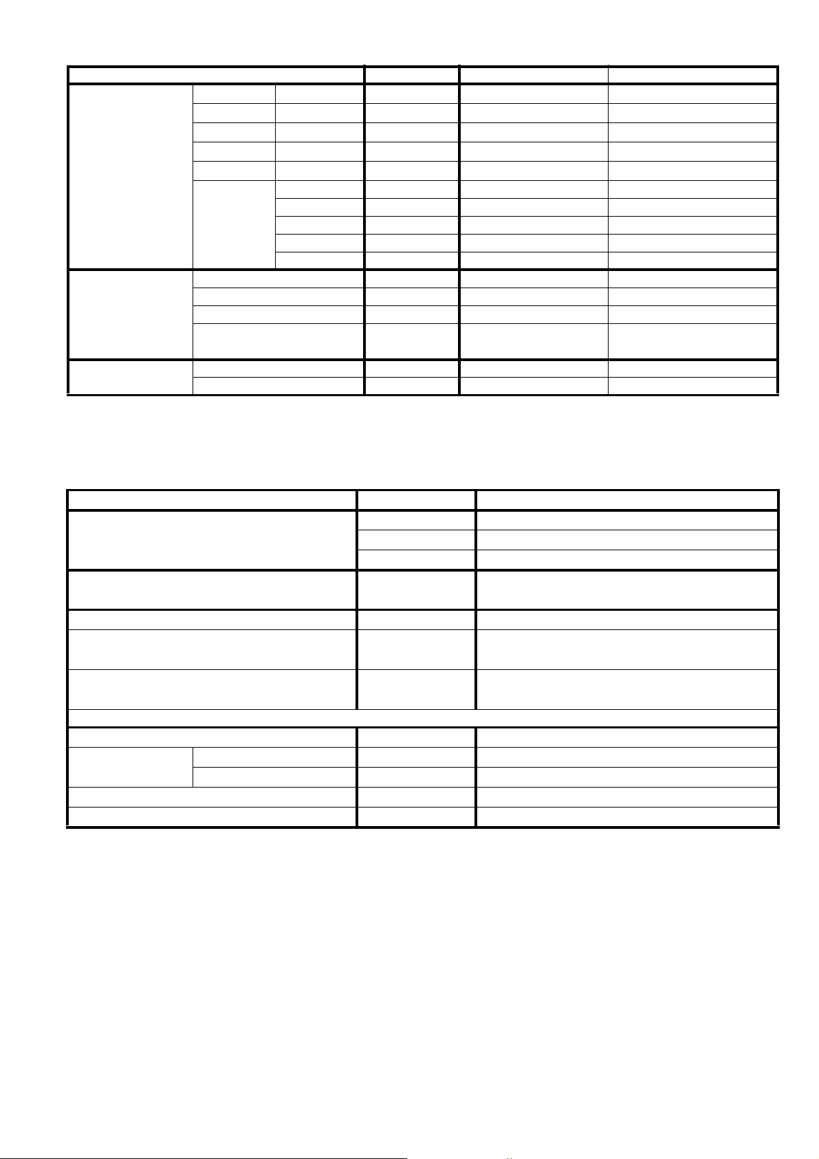
2.2. Sensible Capacity Chart
O CS-CE7GKEW CU-CE7GKE
230V Outdoor Temp. (°C)
Indoor wet
bulb temp.
17.0°C 2.03 1.54 0.44 1.90 1.48 0.47 1.77 1.42 0.51 1.61 1.35 0.55
19.0°C 2.05 0.48
19.5°C 2.23 1.61 0.45 2.09 1.55 0.48 1.94 1.49 0.52 1.77 1.42 0.56
22.0°C 2.43 1.67 0.46 2.27 1.61 0.49 2.12 1.55 0.52 1.92 1.48 0.57
TCSHCIPTCSHCIPTCSHCIPTCSHCIP
O CS-CE9GKEW CU-CE9GKE
230V Outdoor Temp. (°C)
Indoor wet
bulb temp.
17.0°C 2.58 1.96 0.54 2.41 1.88 0.58 2.24 1.80 0.62 2.04 1.71 0.67
19.0°C 2.60 0.59
19.5°C 2.83 2.05 0.55 2.65 1.97 0.59 2.46 1.89 0.63 2.24 1.80 0.68
22.0°C 3.09 2.12 0.56 2.88 2.04 0.60 2.68 1.97 0.64 2.44 1.88 0.70
TCSHCIPTCSHCIPTCSHCIPTCSHCIP
30 35 40 46
30 35 40 46
O CS-CE12GKEW CU-CE12GKE
230V Outdoor Temp. (°C)
Indoor wet
bulb temp.
17.0°C 3.47 2.63 0.84 3.24 2.52 0.91 3.02 2.43 0.97 2.74 2.30 1.05
19.0°C 3.50 0.92
19.5°C 3.81 2.76 0.86 3.56 2.65 0.92 3.31 2.55 0.99 3.01 2.43 1.07
22.0°C 4.15 2.86 0.87 3.88 2.75 0.94 3.61 2.65 1.01 3.28 2.53 1.08
Total Cooling Capacity (kW)
-
TC
Sensible Heat Capacity (kW)
-
SHC
Input Power (kW)
-
IP
Indoor 27°C/19°C
Outdoor 35°C/24°C
TCSHCIPTCSHCIPTCSHCIPTCSHCIP
30 35 40 46
20
Page 21

3 Exploded View and Replacement Parts List
3.1. Indoor Unit
Note
The above exploded view is for the purpose of parts disassembly and replacement.
The non-numbered parts are not kept as standard service parts.
21
Page 22

REF. NO. PART NAME & DESCRIPTION QTY. CS-CE7GKEW CS-CE9GKEW CS-CE12GKEW REMARKS
1 CHASSY COMPLETE 1 CWD50C1513 ←←
2 FAN MOTOR 1 ARW61F8P30AC ←←O
3 CROSS FLOW FAN COMPLETE 1 CWH02C1045 ←←
4 BEARING ASSY 1 CWH64K007 ←←
5 SCREW - CROSS FLOW FAN 1 CWH551146 ←←
6 EVAPORATOR 1 CWB30C2099 ← CWB30C2115
7 FLARE NUT (1/4”) 1 CWT251030 ←←
8 FLARE NUT (3/8”) (1/2”) 1 CWT251031 ← CWT251032
9 CLIP FOR SENSOR 1 CWH32143 ←←
10 DISCHARGE GRILLE COMPLETE 1 CWE20C2621 ←←
11 VERTICAL VANE 12 CWE241157 ←←
12 CONNECTING BAR 1 CWE261092 ←←
13 CONNECTING BAR 2 CWE261071 ←←
14 CONNECTING BAR 1 CWE261091 ←←
15 AIR SWING MOTOR 1 CWA981091 ←←O
17 CAP - DRAIN TRAY 1 CWH521096 ←←
18 HORIZONTAL VANE COMPLETE 1 CWE24C1176 ←←
19 BACK COVER CHASSIS 1 CWD932454 ←←
20 CONTROL BOARD CASING 1 CWH102321 ←←
21 TERMINAL BOARD COMPLETE 1 CWA28C2305 ←←O
23 ELECTRONIC CONTROLLER - MAIN 1 CWA73C2532 CWA73C2533 CWA73C2534 O
24 ELECTRONIC CONTROLLER - POWER 1 CWA744567 ←←O
25 SENSOR COMPLETE 1 CWA50C2122 ←←O
26 CONTROL BOARD FRONT COVER 1 CWH131207 ←←
27 INDICATOR COMPLETE 1 CWE39C1168 ←←O
28 INDICATOR HOLDER 1 CWD932744 ←←
29 INDICATOR HOLDER 1 CWD932745 ←←
30 CONTROL BOARD FRONT COVER CO. 1 CWH13C1171 ←←
31 REMOTE CONTROL COMPLETE 1 CWA75C3006 ←←O
32 FRONT GRILLE COMPLETE 1 CWE11C3676 ←←O
33 INTAKE GRILLE COMPLETE 1 CWE22C1344 ←←
34 GRILLE DOOR 1 CWE14C1010 ←←
35 E-ION FILTER 2 CWD00K1001 ←←
36 SCREW - FRONT GRILLE 2 XTT4+16CFJ ←←
37 CAP - FRONT GRILLE 2 CWH521109 ←←
38 DRAIN HOSE 1 CWH851063 ←←
39 INSTALLATION PLATE 1 CWH361067 ←←
40 BAG COMPLETE - INSTALLATION SCREW 1 CWH82C067 ←←
41 FULCRUM 1 CWH621049 ←←
42 E-ION AIR PURIFYING SYSTEM 1 CWH14C5332 ←←O
43 ION - GENERATOR 1 CWH94C0014 ←←O
(NOTE)
• All parts are supplied from PHAAM, Malaysia (Vendor Code: 061).
• “O” marked parts are recommended to be kept in stock.
22
Page 23

3.2. Outdoor Unit
Note
The above exploded view is for the purpose of parts disassembly and replacement.
The non-numbered parts are not kept as standard service parts.
23
Page 24

REF. NO. PART NAME & DESCRIPTION QTY. CU-CE7GKE CU-CE9GKE CU-CE12GKE REMARKS
1 CHASSY ASS’Y 1 CWD50K2073 ←←
2 SOUND PROOF MATERIAL 1 CWG302314 ←←
3 FAN MOTOR BRACKET 1 CWD541030 ←←
4 SCREW - FAN MOTOR BRACKET 2 CWH551198 ←←
5 FAN MOTOR 1 CWA951536 CWA951553 CWA951542 O
6 SCREW - FAN MOTOR MOUNT 3 CWH55252J ←←
7 PROPELLER FAN ASS’Y 1 CWH03K1010 ←←
8 NUT - PROPELLER FAN 1 CWH56053J ←←
9 COMPRESSOR 1 5RS092XCD01 5RS102XBC01 ← O
10 ANTI - VIBRATION BUSHING 3 CWH50077 ←←
11 NUT - COMPRESSOR MOUNT 3 CWH56000J ←←
12 CONDENSER 1 CWB32C2154 CWB32C1599 ←
13 TUBE ASS’Y CO. (CAP. / CHK VALVE) 1 CWT01C4051 CWT01C4201 CWT01C4202
15 HOLDER COUPLING 1 CWH351023 ←←
16 2-WAYS VALVE (LIQUID) 1 CWB021301 ←←O
17 3-WAYS VALVE (GAS) 1 CWB011374 ← CWB011367 O
19 REACTOR 1 G0C193J00003 ← G0C193J00004 O
20 TERMINAL COVER 1 CWH171039A ←←
21 NUT - TERMINAL COVER 1 CWH7080300J ←←
22 SOUND PROOF BOARD 1 CWH151172 ←←
23A SOUND PROOF MATERIAL 1 CWG302316 ←←
23B SOUND PROOF MATERIAL 1 CWG302317 ←←
24 SENSOR COMPLETE 1 CWA50C2205 ←←O
25 CONTROL BOARD COVER 1 CWH131264 ←←
26 ELECTRONIC CONTROLLER - MAIN 1 CWA73C2542R ← CWA73C2714R O
27 TERMINAL BOARD ASS’Y 1 CWA28K1110J ←←O
28 CABINET SIDE PLATE CO. 1 CWE04C1116 ←←
29 SENSOR COMPLETE 1 CWA50C2391 ←←O
30 CABINET SIDE PLATE 1 CWE041248A ←←
31 CABINET FRONT PLATE CO. 1 CWE06C1039 CWE06C1136 ←
32 CABINET TOP PLATE 1 CWE031014A ←←
33 PLATE - C. B. COVER 1 CWH131301 ←←
34 CONTROL BOARD COVER CO. 1 CWH13C1064 ←←
35 HANDLE 1 CWE161010 ←←
36 OPERATION INSTRUCTIONS (ENG., ESP., PRO., GRE.) 1 CWF565747 ←←
37 INSTALLATION INSTRUCTION (ENG.) 1 CWF613297 ←←
38 4-WAYS VALVE 1 CWB001037J ←←O
39 V - COIL COMPLETE 1 CWA43C2143J ←←O
40 WIR E NET 1 CWD041111A ←←
41 L - TUBE 1 CWH5850080 ←←
42 PACKING - L. TUBE 1 CWB81012 ←←
43 OPERATION INSTRUCTIONS (FRA., DEU., ITA., NED.) 1
44 OPERATION INSTRUCTIONS (BUL., NOR., SWE.) 1
45 INSTALLATION INSTRUCTION (FRA., DEU., ITA., NED.) 1
46 INSTALLATION INSTRUCTION (POR., ESP., BUL., GRE.) 1
47 HOLDER SENSOR 1 CWH321023 ←←
48 SOUND PROOF MATERIAL 1 CWG302315 ←←
49 INSTALLATION INSTRUCTION (NOR., SWE.) 1 CWF613300 ←←
50 INSTALLATION INSTRUCTION (FIN., DAN.) 1 CWF613327
- CWF565748 ←
-
-
-
CWF565749 ←
CWF613298 ←
CWF613299 ←
--
(NOTE)
• All parts are supplied from PHAAM, Malaysia (Vendor Code: 061).
• “O” marked parts are recommended to be kept in stock.
24
[PHAAM] Printed in Malaysia
SFYW0706 - 00
 Loading...