

Page 1
Order No: PHAAM0810022C8
Indoor Unit Outdoor Unit
CS-C7JKD
CS-C9JKD
CS-C12JKD
This service information is designed for experienced repair technicians only and is not designed for use by the general public.
It does not contain warnings or cautions to advise non-technical individuals of potential dangers in attempting to service a product.
Products powered by electricity should be serviced or repaired only by experienced professional technicians. Any attempt to service
or repair the products dealt with in this service information by anyone else could result in serious injury or death.
WARNING
CU-C7JKD
CU-C9JKD
CU-C12JKD
TABLE OF CONTENTS
1. Safety Precautions.............................................3
2. Specification .......................................................5
3. Features ............................................................11
4. Location of Controls and Components .........12
4.1 Indoor Unit..................................................12
4.2 Outdoor Unit...............................................12
4.3 Remote Control ..........................................12
5. Dimensions.......................................................13
5.1 Indoor Unit..................................................13
5.2 Outdoor Unit...............................................14
6. Refrigeration Cycle Diagram...........................15
7. Block Diagram ..................................................16
8. Wiring Connection Diagram............................17
9. Electronic Circuit Diagram ..............................18
10. Printed Circuit Board .......................................19
10.1 Indoor Unit..................................................19
11. Installation Instruction.....................................21
11.1 Select the Best Location ............................21
11.2 Indoor Unit..................................................22
11.3 Outdoor Unit ...............................................25
12. Operation Control.............................................28
12.1 Cooling Operation ......................................28
12.2 Soft Dry Operation......................................29
12.3 Automatic Operation ..................................30
12.4 Indoor Fan Speed Control..........................31
12.5 Outdoor Fan Speed Control .......................32
12.6 Vertical Airflow Direction Control................33
12.7 Horizontal Airflow Direction Control ...........3
12.8 Powerful
12.9 Quiet Operation ..........................................34
12.10 Timer Control..............................................35
12.11 Random Auto Restart Control ....................35
12.12 Remote Control Signal Receiving Sound...35
12.13 Patrol Operation .........................................36
12.14 e-ion operation ...........................................39
13. Protection Control............................................42
13.1 Restart Control (Time Delay Safety Control)
42
13.2 7 Minutes Time Save Control.....................42
13.3 60 Seconds Forced Operation ...................42
13.4 Starting Current Control .............................42
13.5 Freeze Prevention Control .........................43
© Panasonic HA Air Conditioning (M) Sdn. Bhd. 2008
Unauthorized copying and distribution is a violation of
law.
Operation.....................................33
3
Page 2

13.6 Compressor Reverse Rotation Protection
Control ...................................................................43
13.7 Dew Prevention Control .............................44
14. Servicing Mode.................................................45
14.1 Auto OFF/ON Button ..................................45
14.2 Remote Control Button...............................46
15. Troubleshooting Guide....................................47
15.1 Refrigeration cycle system .........................47
16. Disassembly and Assembly Instructions ......49
16.1 Indoor Electronic Controllers, Cross Flow
Fan and Indoor Fan Motor Removal Procedures..49
17. Technical Data ..................................................53
17.1 Thermostat Characteristics ........................53
17.2 Operation Characteristics...........................54
18. Exploded View and Replacement Pars List...60
18.1 Indoor Unit ..................................................60
18.2 Outdoor Unit ...............................................62
2
Page 3
1. Safety Precautions
x Read the following “SAFETY PRECAUTIONS” carefully before perform any servicing.
x Electrical work must be installed or serviced by a licensed electrician. Be sure to use the correct rating of the
power plug and main circuit for the model installed.
x The caution items stated here must be followed because these important contents are related to safety. The
meaning of each indication used is as below. Incorrect installation or servicing due to ignoring of the instruction
will cause harm or damage, and the seriousness is classified by the following indications.
WARNING
CAUTION
x The items to be followed are classified by the symbols:
This symbol denotes item that is PROHIBITED from doing.
x Carry out test running to confirm that no abnormality occurs after the servicing. Then, explain to user the
operation, care and maintenance as stated in instructions. Please remind the customer to keep the operating
instructions for future reference.
1. Do not modify the machine, part, material during repairing service.
This indication shows the possibility of causing death or serious injury.
This indication shows the possibility of causing injury or damage to properties.
WARNING
2. If wiring unit is supplied as repairing part, do not repair or connect the wire even only partial wire break. Exchange the whole wiring unit.
3. Do not wrench the fasten terminal. Pull it out or insert it straightly.
4. Engage dealer or specialist for installation and servicing. If installation of servicing done by the user is defective, it will cause water leakage,
electrical shock or fire.
5. Install according to this installation instructions strictly. If installation is defective, it will cause water leakage, electric shock or fire.
6. Use the attached accessories parts and specified parts for installation and servicing. Otherwise, it will cause the set to fall, water leakage, fire
or electrical shock.
7. Install at a strong and firm location which is able to withstand the set’s weight. If the strength is not enough or installation is not properly done,
the set will drop and cause injury.
8. For electrical work, follow the local national wiring standard, regulation and the installation instruction. An independent circuit and single outlet
must be used. If electrical circuit capacity is not enough or defect found in electrical work, it will cause electrical shock or fire.
9. This equipment is strongly recommended to install with Earth Leakage Circuit Breaker (ELCB) or Residual Current Device (RCD). Otherwise, it
may cause electrical shock and fire in case equipment breakdown or insulation breakdown.
10. Use the specified indoor/outdoor connection cable [1.5 mm2 (1.0 ~ 1.5HP) or 2.5 mm2 (2.0 ~ 2.5HP)], and connect tightly for indoor/outdoor
connection. Connect tightly and clamp the cable so that no external force will be acted on the terminal. If connection or fixing is not perfect, it
will cause heat-up or fire at the connection.
11. Wire routing must be properly arranged so that control board cover is fixed properly. If control board cover is not fixed perfectly, it will cause
heat-up or fire at the connection point of terminal, fire or electrical shock.
12. When carrying out piping connection, take care not to let air substances other than the specified refrigerant go into refrigeration cycle.
Otherwise, it will cause lower capacity, abnormal high pressure in the refrigeration cycle, explosive and injury.
13. Do not install outdoor unit near handrail of veranda. When installing air-conditioner unit at veranda of high rise building, child may
climb up to outdoor unit and cross over the handrail and causing accident.
14. This equipment must be properly earthed. Earth line must not be connected to gas pipe, water pipe, earth of lightning rod and
telephone. Otherwise, it may cause electric shock in case equipment breakdown or insulation breakdown.
15. Keep away from small children, the thin film may cling to nose and mouth and prevent breathing.
16. Do not damage or use unspecified power supply cord. Otherwise it will cause fire or electric shock.
17. Do not modify the length of the power supply cord or use extension cord, and do not share the single outlet with other electric
appliances. Otherwise, it will cause fire or electric shock.
18. During pump down operation, stop the compressor before remove the refrigeration piping. When remove piping while valve at open
condition, burst may occur and cause injury.
19. During installation, before run the compressor, confirm the refrigerant pipes are fixed. Operation of compressor without fixing the piping,
setting the valves at open condition, a burst may occur and cause injury.
3
Page 4
WARNING
20. After completion of installation or service, confirm there is no leakage or refrigerant gas. It may generate toxic gas when the refrigerant
contacts with fire.
21. Ventilate if there is refrigerant gas leakage during operation. It may cause toxic gas when refrigerant contacts with fire.
22. Do not insert your fingers or other objects into the unit, high speed rotating fan may cause injury.
23. Must not use other parts except original parts described in catalog and manual.
CAUTION
1. Do not install the unit at place where leakage of flammable gas may occur. In case gas leaks and accumulates at surrounding of the
unit, it may cause fire.
2. Carry out drainage piping as mentioned in installation instructions. If drainage is not perfect, water may enter the room and damage
the furniture.
3. Tighten the flare nut with torque wrench according to specified method. If the flare nut is over-tightened, after a long period, the flare
may break and cause refrigerant gas leakage.
4. Do not touch outdoor unit air inlet and aluminium fin. It may cause injury.
5. Select an installation location which is easy for maintenance.
6. Pb free solder has a higher melting point than standard solder; typically the melting point is 50°F – 70°F (30°C – 40°C) higher. Please use
a high temperature solder iron. In case of the soldering iron with temperature control, please set it to 700 ± 20°F (370 ± 10°C).
Pb free solder will tend to splash when heated too high (about 1100°F / 600°C).
7. Power supply connection to the air conditioner. Connect the power supply cord of the air conditioner to the mains using one of the following
methods.
Power supply point shall be the place where there is ease for access for the power disconnection in case of emergency. In some countries,
permanent connection of this room air conditioner to the power supply is prohibited.
i. Power supply connection to the receptacle using a power plug.
Use an approved 15/16A (1.0~1.5HP) or 16A (2.0HP) or 20A (2.5HP) power
plug with earth pin for the connection to the socket.
ii. Power supply connection to a circuit breaker for the permanent component.
Use an approved 15/16A (1.0~1.5HP) or 20A (2.5HP) circuit
breaker for the permanent connection. It must be a double pole switch with a minimum 3.0 mm contact gap.
8. Do not release refrigerant during piping work for installation, servicing, reinstallation and during repairing a refrigerant parts.
Take care of the liquid refrigerant, it may cause frostbite
9. Installation or servicing work: It may need two people to carry out the installation or servicing work.
10. Do not install this appliance in a laundry room or other location where water may drip from the ceiling, etc.
11. Do not sit or step on the unit, you may fall down accidentally.
12. Do not touch the sharp aluminium fin, sharp parts may cause injury.
4
Page 5
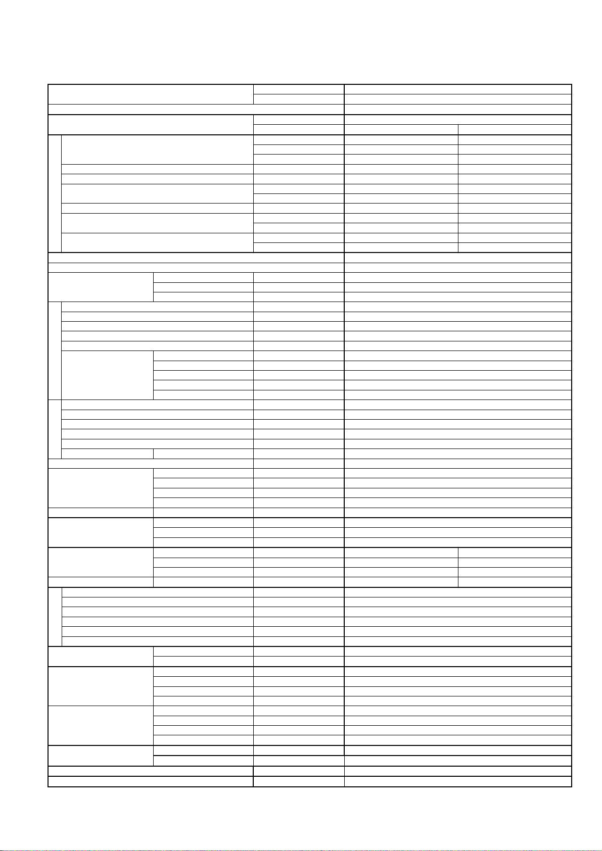
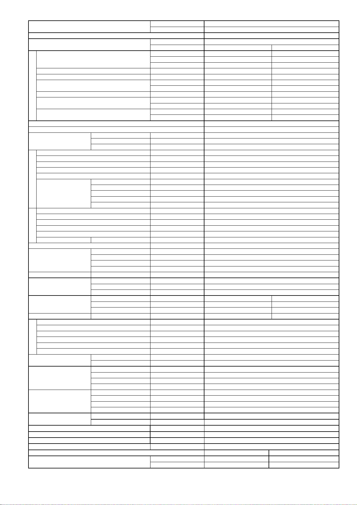
2. Specification
Model
Performance Test Condition NEW JIS
Power Supply
Capacity
Running Current A 3.0 2.9
Input Power W 590 640
EER
Cooling
Compressor
Indoor Fan
Outdoor Fan
Piping
Speed
Speed Hi rpm 800 - 830
Indoor Airflow
Outdoor Airflow Hi m3/min (ft3/min) 28.8 (1020) - 29.2 (1040)
Refrigeration Cycle
Dimension
Weight Net (I/D / O/D) kg (lb) 9 (20) 22 (49)
Drain Hose
Indoor Heat
Exchanger
Outdoor Heat
Exchanger
Air Filter
Power Factor % 96 92
Indoor Noise (H / L)
Outdoor Noise (H / L)
Max Current (A) / Max Input Power (W) 3.4 / 760
Starting Current (A) 12.4
Type Hermetic Motor
Motor Type Induction (2-poles)
Output Power W 550
Type Cross-Flow Fan
Material ASG20K1
Motor Type Induction (4-poles)
Input Power W 36.7 - 38.1
Output Power (I/D / O/D) W 19
QLo rpm 690 - 690
Lo rpm 740 - 740
Me rpm 840 - 840
Hi rpm 960 - 960
SHi rpm 1050 - 1050
Type Propeller Fan
Material PP Resin
Motor Type Induction (6-poles)
Input Power W 66.0 - 75.0
Output Power W 30
Moisture Removal L/h (Pt/h) 1.3 (2.7)
Lo m3/min (ft3/min) 6.1 (215) - 6.1 (215)
Me m3/min (ft3/min) 6.9 (244) - 6.9 (244)
Hi m3/min (ft3/min) 7.9 (279) - 7.9 (279)
SHi m
Control Device Capillary tube
Refrigerant Oil cm3 Atmos NM56M or Suniso 4GDID (290)
Refrigerant Type g (oz) R22, 450 (15.9)
Height(I/D / O/D) mm (inch) 290 (11-7/16) 510 (20-3/32)
Width (I/D / O/D) mm (inch) 870 (34-9/32) 650 (25-19/32)
Depth (I/D / O/D) mm (inch) 204 (8-1/16) 230 (9-1/16)
Pipe Diameter (Liquid / Gas) mm (inch) 6.35 (1/4) / 9.52 (3/8)
Standard length m (ft) 7.5 (24.6)
Length range (min – max) m (ft) 3 ~ 10 (9.8 ~ 32.8)
I/D & O/D Height different m (ft) 5 (16.4)
Additional Gas Amount g/m (oz/ft) 10 (0.1)
Length for Additional Gas m (ft) 7.5 (24.6)
Inner Diameter mm 16
Length mm 550
Fin Material Pre Coat
Fin Type Slit Fin
Row x Stage x FPI 2 x 10 x 17
Size (W x H x L) mm 610 x 315 x 25.4
Fin Material Blue Coated
Fin Type Slit Fin
Row x Stage x FPI 1 x 23 x 17
Size (W x H x L) mm 12.7 x 483 x 578.4
Material Polypropelene
Type One-touch
Power Supply Indoor
Power Supply Cord A 10
Indoor CS-C7JKD
Outdoor CU-C7JKD
Phase, Hz SINGLE, 50
V 220 240
kW 2.00 2.02
BTU/h 6820 6890
kcal/h 1720 1740
W/W 3.39 3.15
Btu/hW 11.6 10.8
dB-A 33 / 26 33 / 26
Power Level dB 46 / - 46 / -
dB-A 46 / - 47 / -
Power Level dB 61 / - 62 / -
3
/min (ft3/min) 8.6 (305) - 8.6 (305)
5
Page 6

Thermostat -
Protection Device 2-stage Overload Protector
Dry Bulb Wet Bulb
Indoor Operation Range
Outdoor Operation Range
1. Cooling capacities are based on indoor temperature of 27°C Dry Bulb (80.6°F Dry Bulb), 19.0°C Wet Bulb (66.2°F Wet Bulb) and outdoor air
temperature of 35°C Dry Bulb (95°F Dry Bulb), 24°C Wet Bulb (75.2°F Wet Bulb).
2. Specifications are subjected to change without prior notice for further improvement.
Maximum 32 23
Minimum 16 11
Maximum 43 26
Minimum 16 11
6
Page 7
Model
Indoor CS-C9JKD
Outdoor CU-C9JKD
Performance Test Condition NEW JIS
Power Supply
Phase, Hz SINGLE, 50
V 220 240
kW 2.60 2.65
Capacity
BTU/h 8870 9040
kcal/h 2240 2280
Running Current A 3.8 3.7
Input Power W 800 835
W/W 3.25 3.17
Btu/hW 11.1 10.8
dB-A 36 / 26 36 / 26
Power Level dB 49 / - 49 / -
dB-A 46 / - 47 / -
Power Level dB 61 / - 62 / -
Cooling
EER
Power Factor % 96 94
Indoor Noise (H / L)
Outdoor Noise (H / L)
Max Current (A) / Max Input Power (W) 4.9 / 1.12k
Starting Current (A) 16.0
Type Hermetic Motor
Compressor
Motor Type Induction (2-poles)
Output Power W 700
Type Cross-Flow Fan
Material ASG20K1
Motor Type Induction (4-poles)
Input Power W 36.7 - 38.1
Output Power (I/D / O/D) W 19
QLo rpm 690 - 690
Indoor Fan
Speed
Lo rpm 740 - 740
Me rpm 930 - 930
Hi rpm 1150 - 1150
SHi rpm 1170 - 1170
Type Propeller Fan
Material PP Resin
Motor Type Induction (6-poles)
Input Power W 66.0 - 75.0
Outdoor Fan
Speed Hi rpm 780 - 830
Output Power W 30
Moisture Removal L/h (Pt/h) 1.6 (3.4)
Lo m3/min (ft3/min) 5.8 (205) - 5.8 (205)
Indoor Airflow
Me m3/min (ft3/min) 7.3 (257) - 7.3 (257)
Hi m3/min (ft3/min) 9.0 (318) - 9.0 (318)
SHi m
3
/min (ft3/min) 9.2 (323) - 9.2 (323)
Outdoor Airflow Hi m3/min (ft3/min) 28.8 (1020) - 29.2 (1040)
Control Device Capillary tube
Refrigeration Cycle
Refrigerant Oil cm3 Atmos M60 or Suniso 4GDID
Refrigerant Type g (oz) R22, 480 (16.9)
Height(I/D / O/D) mm (inch) 290 (11-7/16) 510 (20-3/32)
Dimension
Width (I/D / O/D) mm (inch) 870 (34-9/32) 650 (25-19/32)
Depth (I/D / O/D) mm (inch) 204 (8-1/16) 230 (9-1/16)
Weight Net (I/D / O/D) kg (lb) 9 (20) 25 (55)
Pipe Diameter (Liquid / Gas) mm (inch) 6.35 (1/4) / 9.52 (3/8)
Standard length m (ft) 7.5 (24.6)
Length range (min – max) m (ft) 3 ~ 10 (9.8 ~ 32.8)
Piping
I/D & O/D Height different m (ft) 5 (16.4)
Additional Gas Amount g/m (oz/ft) 10 (0.1)
Length for Additional Gas m (ft) 7.5 (24.6)
Drain Hose
Inner Diameter mm 16
Length mm 550
Fin Material Pre Coat
Indoor Heat
Exchanger
Fin Type Slit Fin
Row x Stage x FPI 2 x 10 x 17
Size (W x H x L) mm 610 x 315 x 25.4
Fin Material Blue Coated
Outdoor Heat
Exchanger
Fin Type Slit Fin
Row x Stage x FPI 1 x 23 x 17
Size (W x H x L) mm 12.7 x 483 x 578.4
Air Filter
Material Polypropelene
Type One-touch
Power Supply Indoor
Power Supply Cord A 10
Thermostat -
Protection Device 2-stage Overload Protector
Dry Bulb Wet Bulb
Indoor Operation Range
Maximum 32 23
Minimum 16 11
7
Page 8

Outdoor Operation Range
1. Cooling capacities are based on indoor temperature of 27°C Dry Bulb (80.6°F Dry Bulb), 19.0°C Wet Bulb (66.2°F Wet Bulb) and outdoor air
temperature of 35°C Dry Bulb (95°F Dry Bulb), 24°C Wet Bulb (75.2°F Wet Bulb).
2. Specifications are subjected to change without prior notice for further improvement.
Maximum 43 26
Minimum 16 11
8
Page 9

Model
Indoor CS-C12JKD
Outdoor CU-C12JKD
Performance Test Condition NEW JIS
Power Supply
Phase, Hz SINGLE, 50
V 220 240
kW 3.52 3.54
Capacity
BTU/h 12000 12100
kcal/h 3030 3050
Running Current A 5.3 5.2
Input Power W 1.11k 1.15k
W/W 3.17 3.08
Btu/hW 10.8 10.5
dB-A 39 / 29 39 / 29
Power Level dB 52 / - 52 / -
dB-A 48 / - 49 / -
Power Level dB 63 / - 64 / -
Cooling
EER
Power Factor % 95 92
Indoor Noise (H / L)
Outdoor Noise (H / L)
Max Current (A) / Max Input Power (W) 7.0 / 1.55k
Starting Current (A) 26.0
Type Hermetic Motor
Compressor
Motor Type Induction (2-poles)
Output Power W 950
Type Cross-Flow Fan
Material ASG20K1
Motor Type Induction (4-poles)
Input Power W 46.6 - 49.5
Output Power (I/D / O/D) W 24
QLo rpm 730 - 730
Indoor Fan
Speed
Lo rpm 800 - 800
Me rpm 940 - 940
Hi rpm 1080 - 1080
SHi rpm 1150 - 1150
Type Propeller Fan
Material PP Resin
Motor Type Induction (6-poles)
Input Power W 66.6 - 74.6
Outdoor Fan
Speed Hi rpm 815 - 850
Output Power W 30
Moisture Removal L/h (Pt/h) 2.1 (4.4)
Lo m3/min (ft3/min) 8.0 (283) - 8.0 (283)
Indoor Airflow
Me m3/min (ft3/min) 9.4 (332) - 9.4 (332)
Hi m3/min (ft3/min) 10.8 (381) - 10.8 (381)
SHi m
3
/min (ft3/min) 11.5 (406) - 11.5 (406)
Outdoor Airflow Hi m3/min (ft3/min) 22.0 (780) - 23.6 (830)
Control Device Capillary tube
Refrigeration Cycle
Refrigerant Oil cm3 Atmos NM56M or Suniso 4GDID (350)
Refrigerant Type g (oz) R22, 840 (29.7)
Height(I/D / O/D) mm (inch) 290 (11-7/16) 510 (20-3/32)
Dimension
Width (I/D / O/D) mm (inch) 870 (34-9/32) 650 (25-19/32)
Depth (I/D / O/D) mm (inch) 204 (8-1/16) 230 (9-1/16)
Weight Net (I/D / O/D) kg (lb) 9 (20) 27 (60)
Pipe Diameter (Liquid / Gas) mm (inch) 6.35 (1/4) / 12.70 (1/2)
Standard length m (ft) 7.5 (24.6)
Length range (min – max) m (ft) 3 ~ 15 (9.8 ~ 49.2)
Piping
I/D & O/D Height different m (ft) 5 (16.4)
Additional Gas Amount g/m (oz/ft) 10 (0.1)
Length for Additional Gas m (ft) 7.5 (24.6)
Drain Hose
Inner Diameter mm 16
Length mm 550
Fin Material Pre Coat
Indoor Heat
Exchanger
Fin Type Slit Fin
Row x Stage x FPI 2 x 15 x 17
Size (W x H x L) mm 610 x 315 x 25.4
Fin Material Blue Coated
Outdoor Heat
Exchanger
Fin Type Slit Fin
Row x Stage x FPI 2 x 23 x 17
Size (W x H x L) mm 25.4 x 483 x 553.4:573.4
Air Filter
Material Polypropelene
Type One-touch
Power Supply Indoor
Power Supply Cord A 10
Thermostat -
Protection Device 2-stage Overload Protector
Dry Bulb Wet Bulb
Indoor Operation Range
Maximum 32 23
Minimum 16 11
9
Page 10

Outdoor Operation Range
1. Cooling capacities are based on indoor temperature of 27°C Dry Bulb (80.6°F Dry Bulb), 19.0°C Wet Bulb (66.2°F Wet Bulb) and outdoor air
temperature of 35°C Dry Bulb (95°F Dry Bulb), 24°C Wet Bulb (75.2°F Wet Bulb).
2. Specifications are subjected to change without prior notice for further improvement.
Maximum 43 26
Minimum 16 11
10
Page 11

3. Features
x E-ion Air Purifying System with Patrol Sensor
o Active e-ions are released to catch dust particles and bring them back the large positively charged filter.
o Patrol Sensor color changes to indicate the dirt level in the air
x Long Installation Piping
o CS/CU-C7JK, CS/CU-C9JK, long piping up to 10 meters.
o CS/CU-C12JK, long piping up to 15 meters.
x Easy to use remote control
x Quality Improvement
o Random auto restart after power failure for safety restart operation
o Gas leakage protection
o Prevent compressor reverse cycle
o Inner protector to protect compressor
o Noise prevention during soft dry operation
o Blue coated condenser for high resistance to corrosion
x Operation Improvement
o Quiet mode to reduce the indoor unit operating sound
o Powerful mode to reach the desired room temperature quickly
o 24-hour timer setting
11
Page 12
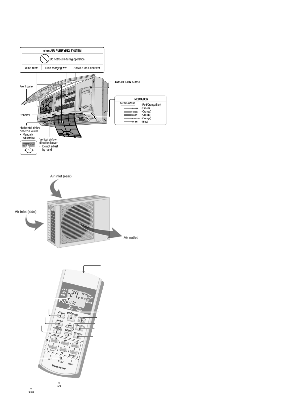
4. Location of Controls and Components
r
C
4.1 Indoor Unit
4.2 Outdoor Unit
4.3 Remote Control
Remote control
display
e-ion operation
Operation mode
Powerful/Quite
operation
Timer setting
lock setting
• For normal operation, the button is not in use.
• Press button to restore the remote control’s default setting.
Transmitte
Off/On
Patrol operation
Temperature setting
Fan speed selection
Airflow direction
adjustment
12
Page 13
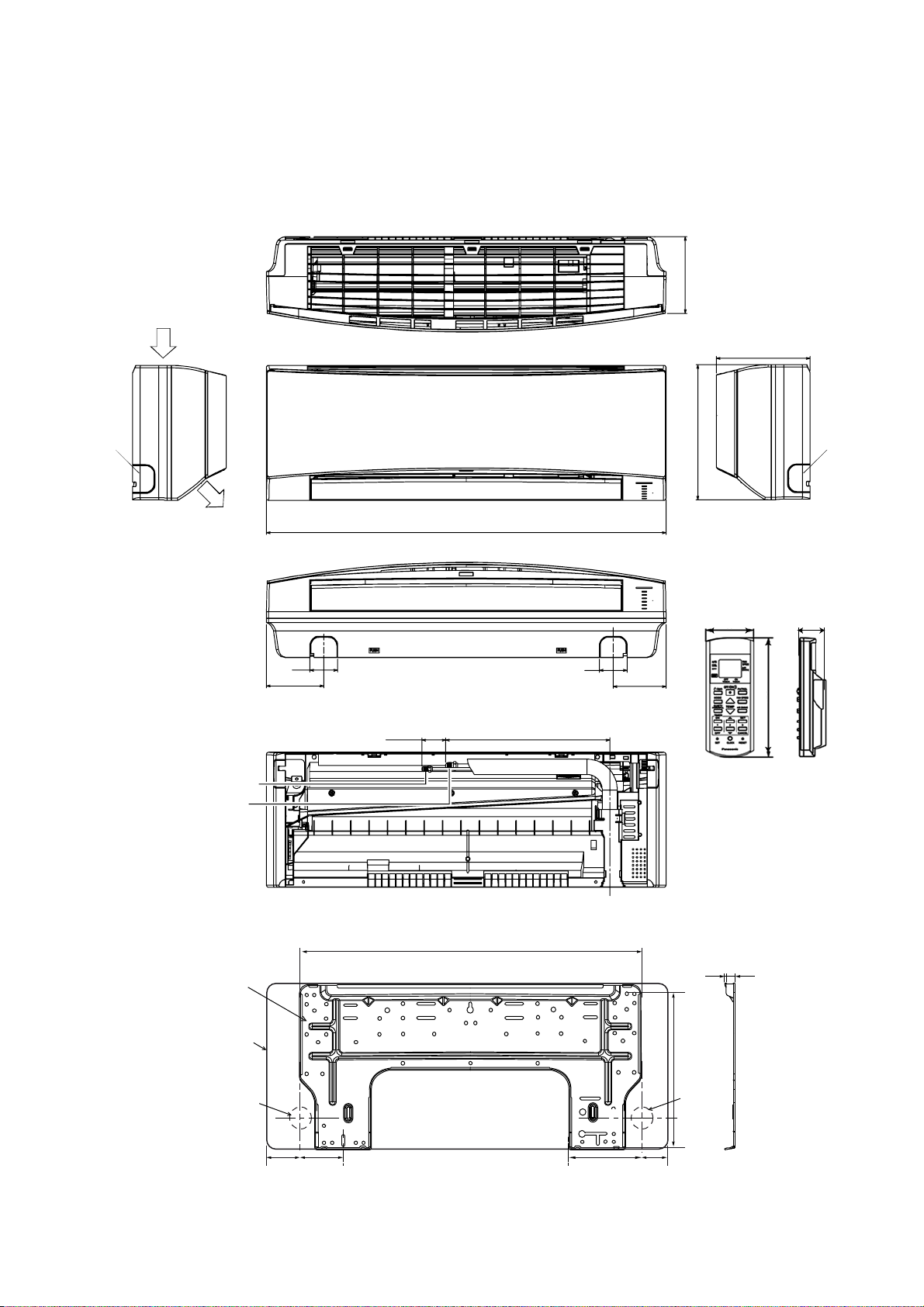
5. Dimensions
5.1 Indoor Unit
<Top View>
164
Left
piping
hole
<Side View>
Air intake
direction
Air outlet
direction
<Front View>
60
125
<Back View>
870
(41-61) 410
<Side View>
204
Right
290
Remote control
47
60
115
piping
hole
22
021
Liquid side
Gas side
Installation
plate
Indoor unit
external
dimensions
line
piping
Relative position between the indoor unit and the installation plate <Front View>
548
Left
hole
165 70.2 115.2 158
2.8 13.5
Right
piping
hole
Unit : mm
13
Page 14
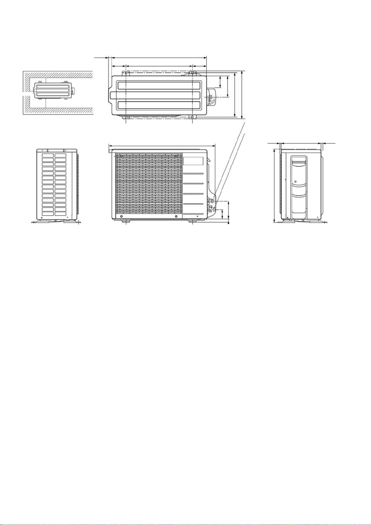
5.2 Outdoor Unit
Space necessary for
installation
18
<Top View>
(650)
88 474 88
10 cm
Unit: mm
10 cm
100 cm
Anchor Bolt Pitch
261 x 474
<Side View>
<Front View>
736
79
134
261
293
2-way valve at Liquid side
(High Pressure)
3-way valve at Gas side
(Low Pressure)
131
70
(18)
<Side View>
12 15
510
230
14
Page 15
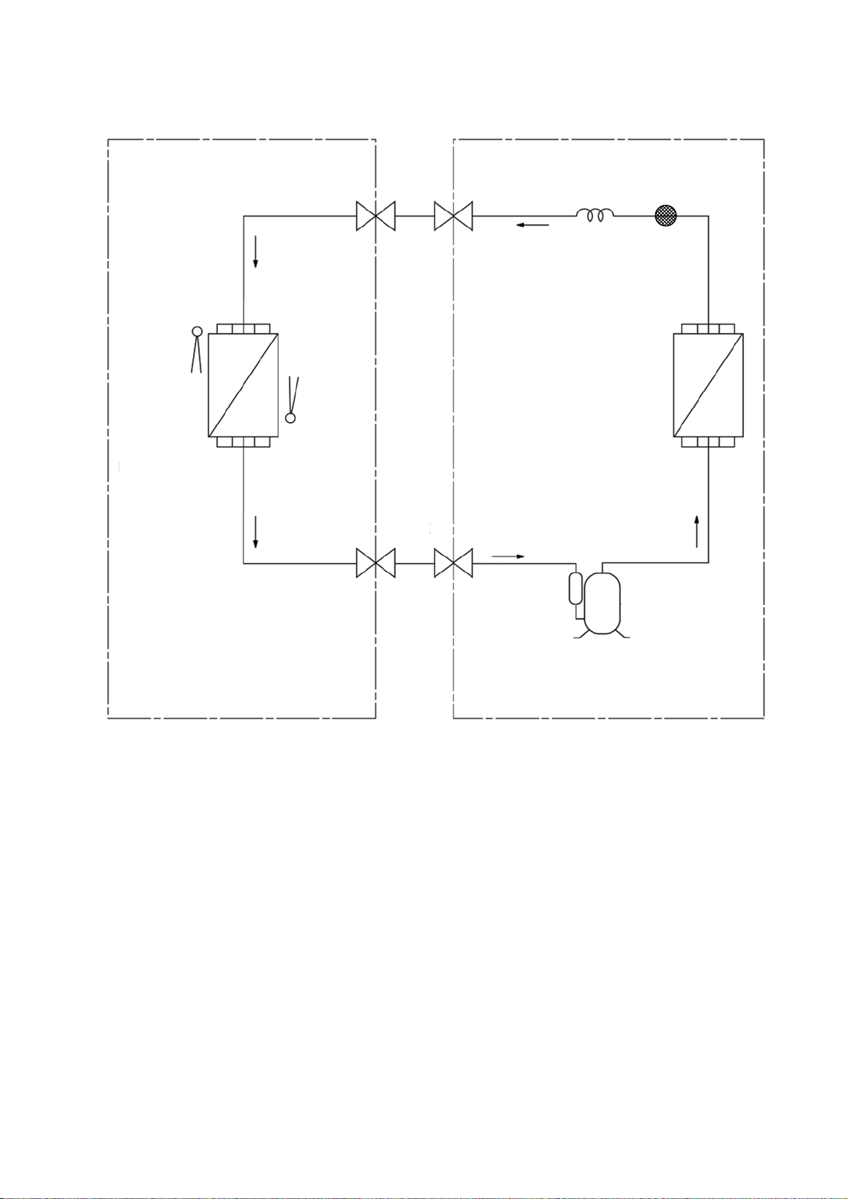
6. Refrigeration Cycle Diagram
INDOOR OUTDOOR
INTAKE
AIR
TEMP
SENSOR
HEAT EXCHANGER
(EVAPORATOR)
PIPE
TEMP
SENSOR
LIQUID
SIDE
2-WAY
VALV E
GAS
SIDE
3-WAY
VALV E
CAPILLARY
TUBE
HEAT EXCHANGER
(CONDENSER)
STRAINER
COMPRESSOR
15
Page 16
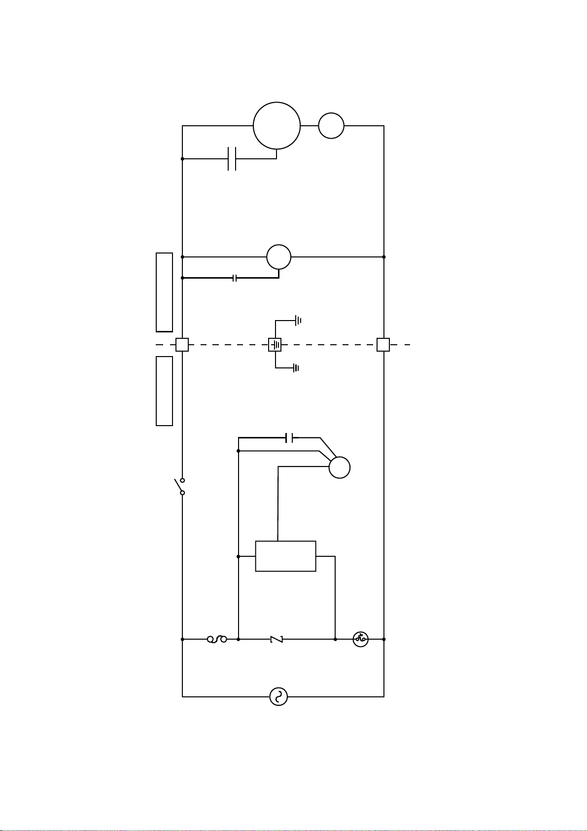
7. Block Diagram
Outdoor UnitIndoor Unit
COMP
O.L.P
FM
1
2
C-FM
FM
RY-PWR
S C
ZNR301
FUSE301
POWER
SUPPLY
16
Page 17
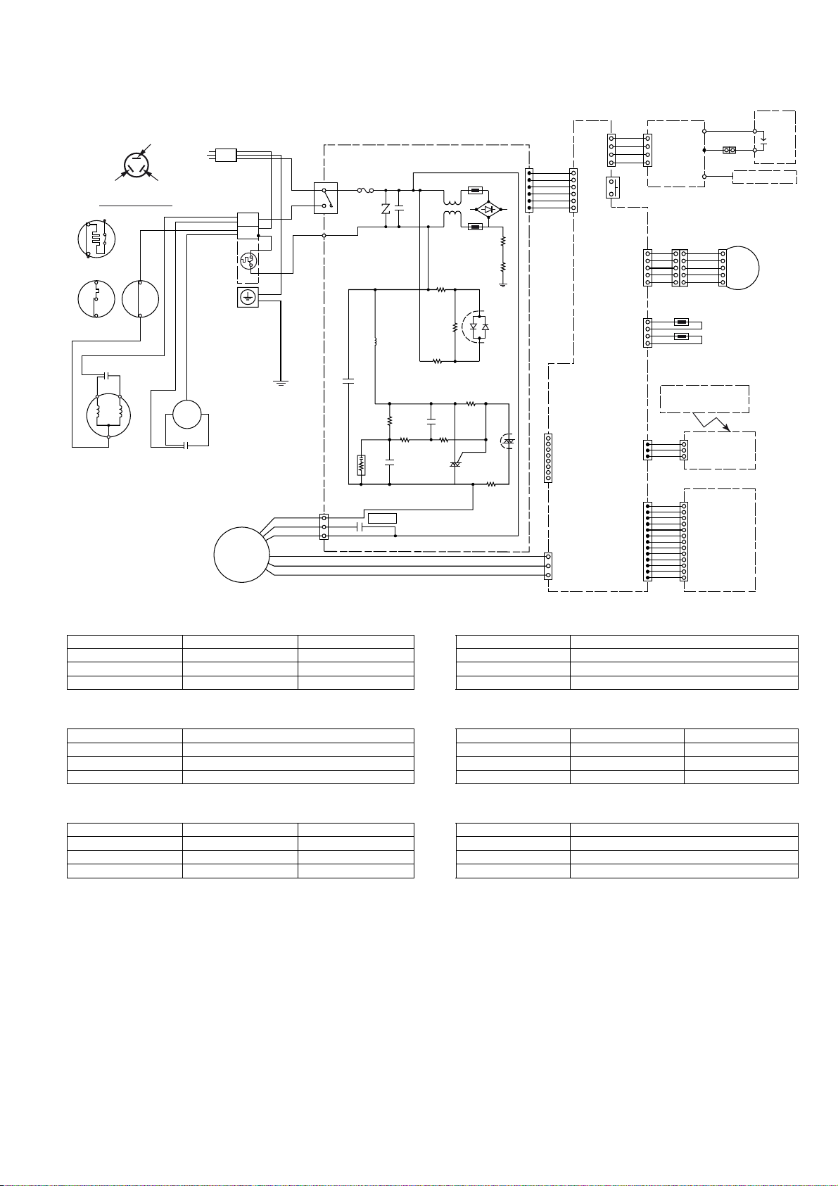
8. Wiring Connection Diagram
GND
GG
W
BR
R
O
Y
P
SENSOR
COMPLETE
1
CN-RCV
ELECTRONIC
3
CONTROLLER
1
CN-DISP
ELECTR ONIC
CONTROLLER
(DISPLAY LED)
13
GAS SENSOR
BL
WIRE HOLDER
1
5
COMPLETE
GENERATOR
YELLOW (YEL)
BLUE (BLU)
COMP. TERMINAL
4
1
ORO.L.P
3
2
OR
1
O.L.P
O.L.P
RED (RED)
GR
2
1
B
TERMINAL
POWER SU PPLY
BOARD
COMPLETE
THERMAL
FUSE
102°C (3A)
4
W
W
W
W
CN-CLN
1
W
W
W
W
W
W
(YLW)
5
AUTO
SW01
SW
CN-DATA1
10
1
CN-STM1
5
4
CN-TH
(RED)
1
BR
BL
W
P
L
AC303
(WHT)
T3.15A L250V
B
1
2
FUSE301
RY-PWR
6
1
CN-DATA1
Y/G
Y/G
HV(-)
4
1
ELECTR ONIC
HV(+)
CONTROLLER
STEPPING MOTOR
11
BR
R
O
Y
P
55
SENSOR 1 (PIPE TEMP. )
SENSOR (AIR TEMP. )
CAPACITOR
BR
B
Y
COMPRESSOR
Remarks:
B:BLUE
BR : BROWN
BL : BLACK
W:WHITE
G : GREEN
R:RED
O : ORANGE
P:PINK
GR : GRAY
Y/G : YELLOW / GREEN
Y
EVAPORATOR
FM
BR
CAPACI TOR
FAN
MOTOR
Resistance of Indoor Fan Motor Windings
CN-PCFM
Y
R
B
W
O
BR
5
C-FM
1
ELECTRONIC CONTROLLER
Resistance of Outdoor Fan Motor Windings
ELECTRONIC
CONTROLLER
1
CN-NMODE
8
1
CN-FB
3
CN-RCV
(YLW)
CN-DISP
(YLW)
3
1
13
W
W
W
W
W
W
W
W
W
W
W
W
W
1
WIRELESS REMOTE
CONTROLLER
MODEL CS-C7JK CS-C9JK MODEL CU-C12JK
CONNECTION CWA921408 CWA921408 CONNECTION CWA951534
BLUE-YELLOW 382 382 BLUE-YELLOW 367
YELLOW-RED 380 380 YELLOW-RED 270
Note: Resistance at 20°C of ambient temperature. Note: Resistance at 20°C of ambient temperature.
Resistance of Indoor Fan Motor Windings Resistance of Compressor Windings
MODEL CS-C12JK MODEL CU-C7JK CU-C9JK
CONNECTION CWA921413 CONNECTION 2RS122D5BG02 2RS146D5AA02
BLUE-YELLOW 316.2 C-R 5.627 4.044
YELLOW-RED 320.8 C-S 12.19 4.246
Note: Resistance at 20°C of ambient temperature. Note: Resistance at 20°C of ambient temperature.
Resistance of Outdoor Fan Motor Windings Resistance of Compressor Windings
MODEL CU-C7JK CU-C9JK MODEL CU-C12JK
CONNECTION CWA951534 CWA951534 CONNECTION 2PS206D3CB02
BLUE-YELLOW 367 367 C-R 2.737
YELLOW-RED 270 270 C-S 4.378
Note: Resistance at 20°C of ambient temperature.
Note: Resistance at 20°C of ambient temperature.
17
Page 18
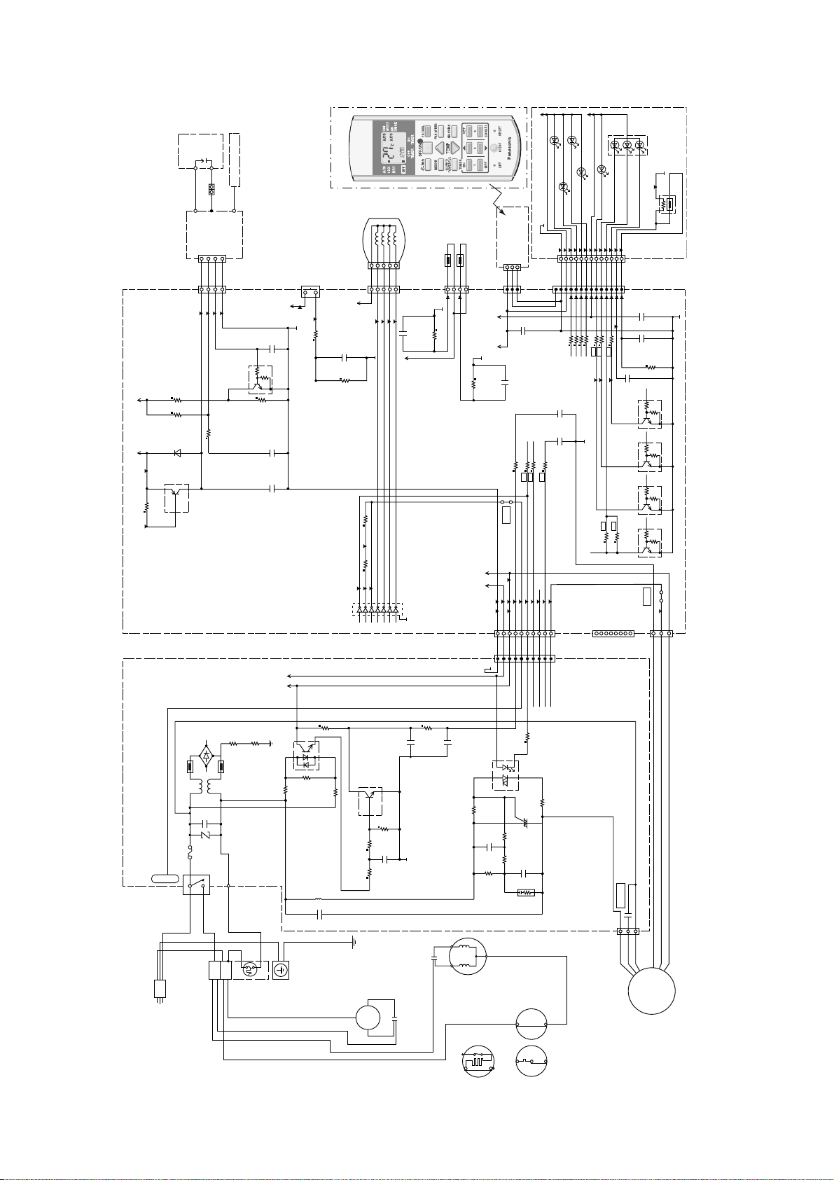
9. Electronic Circuit Diagram
5V
COMPLETE
GENERATOR
REMOTE CONTROL
SENSOR
COMPLETE
ELECTRO NIC
CN-RCV
CONTROLLER
1
5
1
SW
SW01
AUTO
98
1k
R37
BR
12345
12V
16V
C01
0.01μ
10k
STEPPING MO TOR
Y
P
R
O
109
110
CN-STM1
SENSOR 1 (PIPE TEMP.)
4
94
16V
0.1μ
C04
90
R30
20.0k 1%
111
112
5V
R35
31
(RED)
CN-TH
SENSOR ( AIR TEMP.)
1
5V 12V
16V
0.1μ
C08
(YLW)
3
16V
C22
0.1μ
GG
GND
HV(-)
4
W
WWW
432
99
100
101
WIRE HO LDER
W
HV(+)
CONTROLLER
ELECTR ONIC
1
CN-CLN
1
102
Q06
c
5V
97
25V
C24
0.1μ
50V
0.1A
b
47k
4.7k
e
R07 NONE
BL
5V12V
R06 10k
R08 56k
NONE
D02
R09 1k
c
e
Q09
b
R10 18k
-2A
89 91
-32V
ELECTRONIC
CONTROLLER
C20
1000p
25V
C23
0.1μ
R04
1/2W 43 ohm
R05
1/2W 43 ohm
93 95
92
130
16151413121110
9
IC02
1
12V5V
23456
8
7
1k
JP02
5V12V
133
113
114
115
132
134
987654321
10
WWWWW
123456789
R52
R50
116
117
118
WWWWW
SSR I/D
RY-PWR
100/120Hz
R53
R51
119
120
121
DEICE
RY-HOT
SSR O/D
12V
LED202TIMER (ORG)
LED203
LED204
QUIET (ORG)
POWERFUL (ORG)
POWER (GRN) LED201
213
212
211
210
209
208
207
13
WWWWWWWWWWWWW
CN-RCV
1
6
7
11
10112
R15
R14
R13
R12
16V
C16
0.01μ
16V
C17
0.1μ
122
CN-DATA1
1
(YLW)
W
CN-DATA1
10
GND
LED206
LED205
GREEN
E-ION/D UST ( BLU)
206
205
204
203
202
201
ELECTRO NIC
CONTROLLER
RED
BLUE
1
(DISPLAY L ED)
BLUE/ORANGE/RED DISPLAY
215
PATROL TRI-COLOUR
GAS SENSOR
CN-DISP
CN-DISP (YLW)
14
42317
1413
15
25V
C21
0.1μ
R16
R01
256
255
1μ
R60
10V
C39
10.0k 1%
R40
16V
C36
50V
0.1A
b
0.01μ
10k
4.7k
Q03
c
e
50V
0.1A
b
10k
4.7k
Q04
c
e
50V
0.1A
b
10k
4.7k
Q02
c
e
50V
0.1A
b
R11
R59
10k
4.7k
Q07
c
e
JP01
123
CN-NMODE
3
1
8
CN-FB
FUSE301
RY-PWR
TERMINAL
TH301
T3.15A L250V
P
BR
B
BOARD
POWER SU PPLY
DB301
COMPLETE
L
LF301
C309
ZNR301
AC303
PC307
14
R327
R214
3
2
R321
R320
c
Q201
e
b
R326
R331
TH302
R219
R218R212
C209
(WHT)
C301
R215
PC309
61
R126
C120
R125
R119
R216
43
R122
TR202
C111
CR303
ELECTRONIC CONTROLLER
C210
C211
R124
C-FM
W
BL
C330
Y/G
Y/G
1
2
CAPACITOR
BR
Y
EVAPORATOR
1
GR
ORO.L.P
COMPRESSOR
1
2
OR
132
O.L.P O.L.P
THERMAL
FUSE
102°C (3A)
Y
FM
CAPACITO R
BR
B
B
4
5
1
CN-PCFM
B
Y
R
O
W
BR
FAN
MOTOR
18
Page 19
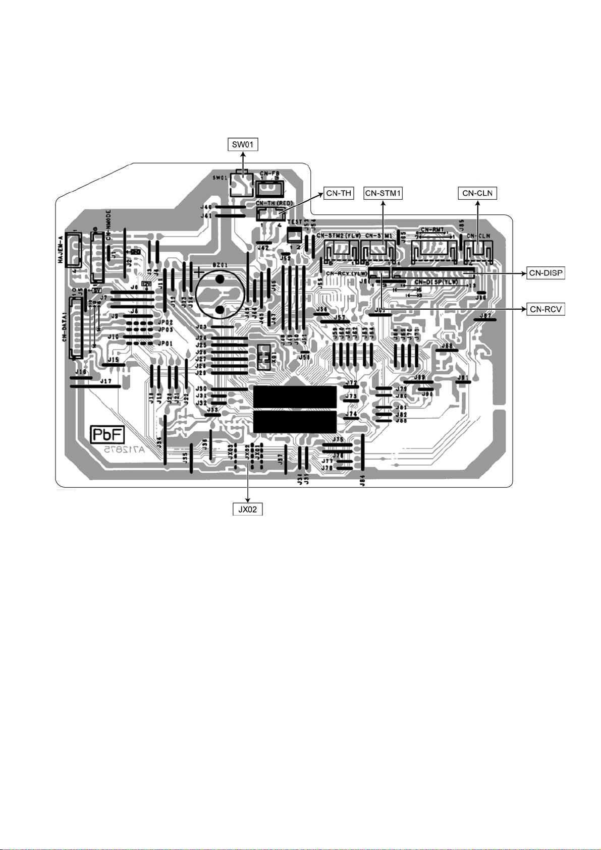
10. Printed Circuit Board
10.1 Indoor Unit
10.1.1 Main Printed Circuit Board
19
Page 20

10.1.2 Power Printed Circuit Board
10.1.3 Indicator
20
Page 21

11. Installation Instruction
11.1 Select the Best Location
11.1.1 Indoor Unit
x Do not install the unit in excessive oil fume area
such as kitchen, workshop and etc.
x There should not be any heat source or steam
near the unit.
x There should not be any obstacles blocking the air
circulation.
x A place where air circulation in the room is good.
x A place where drainage can be easily done.
x A place where noise prevention is taken into
consideration.
x Do not install the unit near the door way.
x Ensure the spaces indicated by arrows from the
wall, ceiling, fence or other obstacles.
x Recommended installation height for indoor unit
shall be at least 2.5 m.
11.1.2 Outdoor Unit
x If an awning is built over the unit to prevent direct
sunlight or rain, be careful that heat radiation from
the condenser is not obstructed.
x There should not be any animal or plant which
could be affected by hot air discharged.
x Keep the spaces indicated by arrows from wall,
ceiling, fence or other obstacles.
x Do not place any obstacles which may cause a
short circuit of the discharged air.
x If piping length is over the [piping length for
additional gas], additional refrigerant should be
added as shown in the table.
Max.
Std.
Eleva-
Length
tion
(m)
(m)
531010 7.5
7.5
531010 7.5
531510 7.5
20 3 25 20 7.5
5
20 3 25 30 7.5
Model
C7JKD
C9JKD
C12JKD
C18JKD
C24JKD
Horse
Power
(HP)
3/4~
1.5HP
2.0~
2.5HP
Piping size
Gas Liquid
3/8"
1/4"
1/2"
5/8"
Example: For C9***
If the unit is installed at 10 m distance, the quantity of
additional refrigerant should be 25 g….(10-7.5) m x 10
g/m = 25 g.
Min.
Piping
Length
(m)
Max.
Piping
Length
(m)
Additional
Refrige-
rant(g/m)
Piping
Length
for add.
gas (m)
11.1.3 Indoor/Outdoor Unit Installation
Diagram
21
Page 22

11.2 Indoor Unit
11.2.1 How to Fix Installation Plate
The mounting wall is strong and solid enough to prevent if from the vibration.
Measuring
Tape
Wall
241.5 mm
128 mm
More than 1
screw
2
B
6
5
C
128
Installation
plate
Wall
More
than 2
1
More than 1
A
Wall
Indoor unit
43
234.5 mm
128 mm
Model
C7JKD, C9JKD, C12JKD
C18JKD, C24JKD
1 2 3 4 5 6
485 mm 82 mm 165 mm 158 mm 43 mm 95 mm
585 mm 82 mm 165 mm 158 mm 169 mm 219 mm
Dimension
The centre of installation plate should be at more than c at right and left of the wall.
The distance from installation plate edge to ceiling should more than d.
From installation plate left edge to unit’s left side is e.
From installation plate right edge to unit’s right side is f.
B : For left side piping, piping connection for liquid should be about g from this line.
ƻ
: For left side piping, piping connection gas should be about h from this line.
1 Mount the installation plate on the wall with 5 screws or more (at least 5 screws).
(If mounting the unit on the concrete wall, consider using anchor bolts.)
o Always mount the installation plate horizontally by aligning the marking-off line with the thread and using
a level gauge.
2 Drill the piping plate hole with ø70mm hole-core drill.
o Putting measuring tape at position as shown in the diagram above.
The hole centre is obtained by measuring the distance namely 128 mm for left and right hole
respectively. Another method is intersection point of arrow mark extension.
The meeting point of the extension arrow mark is the hole center position.
o Drill the piping hole at either the right or the left and the hole should be slightly slanting to the outdoor
side. (refer to step 3)
11.2.2 To Drill a Hole in the Wall and
Install a Sleeve of Piping
1 Insert the piping sleeve to the hole.
2 Fix the busing to the sleeve.
3 Cut the sleeve until it extrudes about 15mm
from the wall.
Caution
When the wall is hollow, please be sure to use the
sleeve for tube ass’y to prevent dangers caused by
mice biting the connecting cable.
4 Finish by sealing the sleeve with putty or
caulking compound at the final stage.
22
Page 23

11.2.3 Indoor Unit Installation
11.2.3.1 For the right rear piping
11.2.3.2 For the right and right bottom
piping
11.2.3.3 For the embedded piping
(This can be used for left rear piping and bottom
piping also.)
23
Page 24

11.2.4 Connect the Cable to the Indoor Unit
1. The inside and outside connecting cable can be
connected without removing the front grille.
2. Connecting cable between indoor unit and
outdoor unit shall be approved polychloroprene
sheathed 3 x 1.5 mm
2
(2.0 ~ 2.5HP) flexible cord, type designation
mm
245 IEC 57 or heavier cord.
Secure the connecting cable onto the control board with the holder.
This equipment must be properly earthed.
x Ensure the colour of wires of outdoor unit and the terminal Nos. are the same to the indoor’s respectively.
x Earth wire shall be Yellow/Green (Y/G) in colour and longer than other AC wires for safety reason.
2
(3/4 ~ 1.5HP) or 3 x 2.5
24
Page 25

11.2.5 Wire Stripping And Connecting Requirement
11.3 Outdoor Unit
11.3.1 Install the Outdoor Unit
x After selecting the best location, start installation according to indoor/outdoor unit installation diagram.
1 Fix the unit on concrete or rigid frame firmly and horizontally by bolt nut (ø10mm).
2 When installing at roof, please consider strong wind and earthquake.
Please fasten the installation stand firmly with bolt or nails.
AB
C
Model A B C D
C7JKD, C9JKD,
C12JKD
C18JKD 570 mm 105 mm 18.5 mm 320 mm
C24JKD 612.5 mm 131 mm 19 mm 383 mm
474 mm 87 mm 18.5 mm 261 mm
D
11.3.2 Connecting the Piping
11.3.2.1 Connecting the piping to
indoor unit
Please make flare after inserting flare nut (locate at
joint portion, of tube assembly) onto the copper pipe.
(In case of using long piping)
Connect the piping
x Align the center of piping and sufficiently tighten
the flare nut with fingers.
x Further tighten the flare nut with torque wrench in
specified torque as stated in the table.
11.3.2.2 Connecting the piping to
outdoor unit
Decide piping length and then cut by using pipe cutter.
Remove burrs from cut edge.
Make flare after inserting the flare nut (locate at valve)
onto the copper pipe.
Align center of piping to valves and then tighten with
torque wrench to the specified torque as stated in the
table.
Piping size Torque
1/4” (6.35 mm) [18 N•m (1.8 kgf.m)]
3/8” (9.52 mm) [42 N•m (4.3 kgf.m)]
1/2” (12.7 mm) [55 N•m (5.6 kgf.m)]
5/8” (15.88 mm) [65 N•m (6.6 kgf.m)]
3/4” (19.05 mm) [100 N•m (10.2 kgf.m)]
Do not over tighten, over tightening cause gas leakage
WARNING
Spanner
or Wrench
To rq u e
wrench
25
Page 26

11.3.3 Evacuation of the Equipment
1 Connect a charging hose with a push pin to the Low side of a charging set and the service port of the 3-way
valve.
o Be sure to connect the end of the charging hose with the push pin to the service port.
2 Connect the center hose of the charging set to a vacuum pump.
3 Turn on the power switch of the vacuum pump and make sure that the needle in the gauge moves from 0
cmHg (0 MPa) to -76 cmHg (-0.1 MPa). Then evacuate the air approximately ten minutes.
4 Close the Low side valve of the charging set and turn off the vacuum pump. Make sure that the needle in the
gauge does not move after approximately five minutes.
Note: BE SURE TO TAKE THIS PROCEDURE IN ORDER TO AVOID REFRIGERENT GAS LEAKAGE.
5 Disconnect the charging hose from the vacuum pump and the service port of the 3-way valve.
6 Tighten the service port caps of the 3-way valve at a torque of 18 N•m with a torque wrench.
7 Remove the valve caps of both of the 2-way valve and 3-way valve. Position both of the valves to “OPEN”
using a hexagonal wrench (4 mm).
8 Mount valve caps onto the 2-way valve and the 3-way valve.
o Be sure to check for gas leakage.
x If gauge needle does not move from 0 cmHg (0 MPa) to -76 cmHg (-01 MPa), in the step e above take the following measure:
o If the leak stops when the piping connections are tightened further, continue working from step e.
o If the leak does not stop when the connections are retightened, repair location of leak.
o Do not release refrigerant during piping work for installation and reinstallation.
o Take care of the liquid refrigerant, it may cause frostbite.
CAUTION
11.3.4 Connect the Cable to the Outdoor Unit
1 Remove the control board cover from the unit
by loosening the screw.
2 Connecting cable between indoor unit and
outdoor unit shall be approved
polychloroprene sheathed 3 x 1.5mm
1.5HP) or 3 x 2.5mm
2
(2.0 ~ 2.5HP) flexible
cord, type designation 245 IEC 57 or heavier
cord.
3 Secure the cable onto the control board with
the holder (clamper).
4 Attach the control board cover back to the
original position with the screw.
5 For wire stripping and connection requirement,
refer to instruction g of the indoor unit.
2
(3/4 ~
26
This equipment must be properly earthed.
x Earth wire shall be Yellow/Green (Y/G) in colour
and longer than other AC wires for safety reason.
Page 27

11.3.5 Pipe Insulation
1 Please carry out insulation at pipe connection portion as mentioned in Indoor/Outdoor Unit Installation
Diagram. Please wrap the insulated piping end to prevent water from going inside the piping.
2 If drain hose or connecting piping is in the room (where dew may form), please increase the insulation by
using POLY-E-FOAM with thickness 6mm or above.
11.3.5.1 Cutting and flaring the piping
1 Please cut using pipe cutter and then remove the burrs.
2 Remove the burrs by using reamer. If burrs are not removed, gas leakage may be caused. Turn the piping
end down to avoid the metal powder entering the pipe.
3 Please make flare after inserting the flare nut onto the copper pipes.
27
Page 28

12. Operation Control
g
12.1 Cooling Operation
x Cooling operation can be set using remote control.
x This operation is applied to cool down the room temperature to the setting temperature sets by the remote control.
x The remote control setting temperature, which takes the reading of intake air temperature sensor, can be
adjusted from 16°C to 30°C.
x During cooling operation, the compressor will stop and restart as shown in figure below:
Remote Control
temperature
settin
12.1.1 Cooling Operation Time Diagram
Compressor-ON level
Intake Air
Temperature
Compressor-OFF level
1.5°C
(Setting Temperature)
a b c d e f g h i j k l m n o p q r s t u v w x y z
Intake air
temperature
Compressor ON
1.5ƱC
Compressor OFF
Indoor Heat
Time Frame
Compressor
Indoor Fan
Outdoor Fan
Operation LED
<Description of operation>
a – b, g – h : Minimum 60 seconds forced operation Operation
d – g, s – u : Minimum 3 minutes restart control (Time Delay Safety Control)
h – o : Maximum 7 minutes time save control Stop
q – u : Freeze Prevention Control
1’ 3‘ 1’ 7’ 1’ 4’
Exchanger
Temperature
10°C
2°C
3’
30”
28
Page 29

12.2 Soft Dry Operation
x Soft Dry operation can be set using remote control.
x Soft Dry operation is applied to dehumidify and to perform a gentle cooling to the room.
x This operation starts when the intake air temperature sensor reaches -1.5°C from the setting temperature on the
remote control.
x When operation begins, Soft Dry will be switched ON for a maximum 10 minutes, then Soft Dry operation will be
turned OFF for a minimum 6 minutes. After that, the Soft Dry operation will be ON and OFF based on the setting
temperature as shown in figure below.
x However after 3 minutes of compressor off, during Soft Dry OFF (within 6 minutes Soft Dry restart control), the
indoor unit will start to operate at normal Cooling mode if the intake temperature is higher than Cooling ON point.
Cooling OFF,
Soft Dry ON point
Soft Dry OFF point
Intake air
temperature
Soft Dry OFF
Cooling
Dry
Cooling ON point
1.5ƱC
1.0ƱC
Soft Dry ON point
Compressor
ON
Compressor
OFF
12.2.1 Soft Dry Operation Time Diagram
Intake Air Temperature
1.5°C Cooling ON
Set Temp.
Cooling OFF
1.0°C
Dry OFF, ON
Time Frame
Compressor
Indoor Fan Lo- Lo- * * Lo- * * Lo- Lo- Lo- Lo- * Lo-
Outdoor Fan
Operation LED
<Description of operation>
g – h, l – m, o – p : Minimum 60 seconds forced operation
a – c
c – e : 10 minutes dry operation
e – g, i – k, m – o, v – x
t – x : Freeze Prevention Control
* : Indoor fan OFF for 40” and then rotates at Lo-
a b c d e f g h i j k l m n o p q r s t u v w x y z
Indoor Heat
Exchanger
Temperature
10’ 6’ 1’ 6’ 1’ 6’ 1’ 4’ 6’
: Minimum 3 minutes restart control (Time Delay Safety Control) –
Cooling operation
: Minimum 6 minutes restart control (Time Delay Safety Control) –
Soft dry operation
10°C
2°C
Operation
Stop
29
Page 30

12.3 Automatic Operation
x Automatic operation can be set using remote control.
x This operation starts to operate with indoor fan at SLo speed for 20 seconds to judge the intake air temperature.
x After judged the temperature, the operation mode is determined by referring to the below standard.
Intake Air
Temperature
x Then, the unit starts to operate at determined operation mode, until it is switched off using remote control, with
the setting temperature as shown in table below.
Cooling Operation 25°C
Soft Dry Operation 22°C
Setting Temperature (Standard)
x The setting temperature for all the operations can be changed one level up or one level down from the standard
temperature as shown in table below by pressing the temperature up or temperature down button at remote
control.
Higher Æ +2°C 27°C 24°C
Standard Æ ±0°C 25°C 22°C
Lower Æ -2°C 23°C 20°C
Cooling Soft Dry
x The operation mode judging temperature and standard setting temperature can be increased by 2°C
permanently, by open the circuit of JX03 at indoor unit’s printed circuit board.
Intake Air
Temperature
25°C
Cooling Operation
Soft Dry Operation
23°C
Cooling Operation 27°C
Soft Dry Operation 24°C
Cooling Operation
Soft Dry Operation
Setting Temperature (Standard)
30
Page 31

12.4 Indoor Fan Speed Control
x Indoor fan speed can be set using remote control
12.4.1 Fan Speed Rotation Chart
SHi 1050 1170 1150
Hi 960 1150 1080
Me 840 930 940
HLo 820 820 840
CLo 740 740 800
Lo- 700 700 760
SLo 680 680 740
QHi 890 1080 1010
QMe 770 860 870
QLo 690 690 730
CS-C7JKD CS-C9JKD CS-C12JKD
12.4.2 Automatic Fan Speed Control
x When set to Auto Fan Speed, the fan speed is adjusted between maximum and minimum setting as shown in the
table.
o Fan speed rotates in the range of Hi and Me.
o Deodorizing Control will be activated.
SHi Hi Me HLo CLo Lo- SLo Stop
Manual
Manual
Manual
Manual
Manual
Manual
Cooling
Powerful
Soft Dry
Powerful
Normal
Quiet
Normal
Quiet
Mode Judgment
x Auto Fan Speed during cooling operation:
1 Indoor fan will rotate alternately between off and on as shown in below diagram.
2 At the beginning of each compressor starts operation, indoor fan speed increases gradually for deodorizing
purpose.
3 For the first time the compressor operates, indoor fan will be switched to Hi fan speed from Lo- after 70
seconds from the start of compressor. This cause the room temperature to achieve the setting temperature
quickly.
4 During compressor stops, indoor fan will operate at Lo- for the beginning 20 seconds to prevent higher
volume of refrigerant in liquid form returning to the compressor.
5 After the compressor turned off for 3 minutes, indoor fan will start to operate at Lo- to circulate the air in the
room. This is to obtain the actual reading of the intake air temperature.
6 For the resume of compressor operation, indoor fan will operate at Me fan speed to provide comfort and
lesser noise environment, after 70 seconds from the restarts of compressor.
Hi
Me
Lo
Auto
QHi Hi-70
QMe Me-70
QLo CLo-70
Auto Hi-70 Me-70
Auto
Auto
Auto
Auto
Fan Speed (rpm) Speed
31
Page 32

*1 *2
Indoor Fan
Compressor ON OFF ON
*1 Fan Speed is Hi until the compressor stops (when the room temperature reaches setting
temperature).
*2 Fan Speed is Me after the compressor restarts.
Lo- Lo- Lo- Lo-
Stop
40” 30” 20” 160” 40” 30”
Variable RPM
Stop
x Auto Fan Speed during Soft Dry operation:
1 Indoor fan will rotate alternately between off and Lo-.
2 At the beginning of each compressor starts operation, indoor fan will increase fan speed gradually for
deodorizing purpose.
3 When compressor turned off for 6 minutes, indoor fan will start at Lo- to circulate the air in the room. This is
to obtain the actual reading of intake air temperature.
Lo- Lo- Lo-
Indoor Fan
Compressor ON OFF ON
Stop Stop Stop
40” 6’ 40”
12.4.3 Manual Fan Speed Control
x Manual fan speed adjustment can be carried out by using the Fan Speed selection button at the remote control.
x There are 3 types of fan speed settings: Lo, Me, Hi.
12.4.4 Indoor Fan Motor rpm Abnormal Control
x Immediate after the fan motor is started, rpm abnormal control is performed every second.
x During fan motor on, if fan motor feedback 2550 rpm or < 50 rpm continuously for 10 seconds, the fan motor
error counter increased; fan motor is then stopped and restarted. If the fan motor error counter increased to 7,
then air conditioner will stop operation.
12.5 Outdoor Fan Speed Control
x There is only one speed for outdoor fan motor.
x When the air conditioner is turned on, the compressor and the outdoor fan will operate simultaneously.
x Likewise, both compressor and outdoor fan will stop at the same time if the unit is turned off.
32
Page 33

12.6 Vertical Airflow Direction Control
12.6.1 Auto Control
x When the vertical airflow direction is set to Auto using the remote control, the louver swings up and down as
shown in the diagram.
x When stops operation using the remote control, the discharge vent is reset and stops at the closing position.
x During Cooling operation or Soft Dry operation, indoor fan motor may stop to rotate at certain periods. At that
condition, the louver will stop swinging.
Closing
position
/ 135°
22°
12.6.2 Manual Control
x When the vertical airflow direction is set to Manual using the remote control, the automatic airflow is released and
the airflow direction louver move up and down in the range shown in the diagram.
x The louver can be adjusted by pressing the button to the desired louver position.
x When stop operation using the remote control, the discharge vent is reset, and stop at the closing position.
Closing
position
/ 135°
Horizontal
Upper limit for cooling mode
and soft dry mode/11°
Swing up and down
Lower limit for cooling mode and
soft dry mode/33°
Horizontal
Upper limit for
11°
16°
21°
27°
Lower limit for cooling mode
33°
and soft dry mode
cooling mode and
soft dry mode
12.7 Horizontal Airflow Direction Control
The horizontal airflow direction louvers can be adjusted manually by hand.
12.8 Powerful Operation
x To achieve the setting temperature quickly.
x When powerful operation is set, the setting temperature will be automatically decreased 3°C internally against
the present setting temperature (Lower temperature limit: 16°C).
x This operation automatically running under Shi fan speed (Cooling), Lo- Fan Speed (Soft Dry).
x Vertical Airflow Direction:
o In “Manual” setting, the vane will automatically shift down 10° lower than previous setting.
o In “Auto” setting, the vane will automatically swing up and down. However the lower limit will be shifted 10°
downward.
x Powerful operation stops when:
o Quiet/Powerful button is pressed again
o Powerful operation has operate for 15 minutes
o Stopped by OFF/ON operation button.
o Timer OFF activates
o Operation mode is changed
33
Page 34

12.9 Quiet Operation
(For Cooling Operation or cooling region of Soft Dry Operation)
x To provide quiet cooling operation condition.
x Once the Quiet Operation is set at the remote control, the Quiet LED illuminated. The sound level will reduce
around 2dB(A) for Lo fan speed or 3dB(A) for Hi/Me fan speed against the present operation sound level.
x Dew formation become severe at Quite Lo Cool, therefore Quiet Lo cool operated only for 2 hours (1 hour QLo, 1
hour QLo + 80 rpm). After that, it goes back to Lo cool (However Quiet LED remains illuminated).
x Manual Airflow Direction:
o RPM control during Lo cool
Quiet
LED
Lo Lo QLo+140 Lo QLo+140
QLo+80 QLo+80
Fan
QLo QLo
Time (Hour)
1.0 H 1.0 H 1.0 H 1.0 H
OFF ON OFF ON
Press
Quiet
o RPM control during Hi & Me cool
Press Quiet Cancel Quiet Press Quiet
Quiet LED OFF ON OFF ON
Time (Hour)
Hi/Me Hi/Me Fan
Q Hi/Q Me Q Hi/Q Me
x Auto Fan Speed
Quiet Hi (if before thermo off)
Indoor
fan
Compressor ON OFF ON
Quiet ME (after thermo off)
Lo- Lo- Variable Lo- Lo-
Stop 30” 20” RPM Stop 30”
40” 160” 40”
x Quiet operation stops when:
o Quiet button is pressed again.
o Stopped by OFF/ON operation button.
o Timer OFF activates.
o Operation mode button is changed.
Press
Quiet
Press
Quiet
Speed
Lo to QLo : about 20 rpm / 0.05 sec
QLo to QLo+80 : about 10 rpm / 2 sec
Or QLo+80 to QLo+140
34
Page 35

12.10 Timer Control
12.10.1 ON Timer
x When the ON Timer is set using the remote control, the unit will start to operate slightly before the set time, so
that the room will reach nearly to the set temperature by the set time.
x For Cooling and Soft Dry operation, the operation will start 15 minutes before the set time.
x For Automatic operation, the indoor fan will operate at SLo speed for 20 seconds, 30 minutes before the set time
to detect the intake air temperature to determine the operation mode. The Power indicator will blink at this time.
12.10.2 OFF Timer
x When the OFF Timer is set by using the remote control, the unit will stop operate according to the desired setting.
Notes:
1 By pressing ON/OFF operation button, the ON Timer or OFF Timer setting will not be cancelled.
2 To cancel the previous timer setting, press CANCEL button.
3 To activate the previous timer setting, press SET button.
4 If main power supply is switched off, the Timer setting will be cancelled.
12.11 Random Auto Restart Control
x If there is a power failure during operation, the air conditioner will automatically restart after 3 to 4 minutes when
the power is resumed.
x It will start with previous operation mode and airflow direction.
x If there are more than one air conditioner unit in operation and power failure occur, restart time for each unit to
operate will be decided randomly using 4 parameters: intake air temperature, setting temperature, fan speed and
air swing louver position.
x This random Auto Restart Control is not available when Timer is set.
12.12 Remote Control Signal Receiving Sound
x Short beep sound will be heard when turn ON the air conditioner or enabling other operations.
x Long beep sound will be heard when turn OFF the air conditioner or disabling other operations.
35
Page 36

12.13 Patrol Operation
1
Indicator LED
Operation stop
Power e-ion Patrol
x Press “OFF/ON”
x OFF timer activates
x ON Timer activates
3
Cooling Mode only
Indicator LED
Power e-ion Patrol
LED off
LED on
x Press “OFF/ON”
x Press “Patrol”
x Press “Patrol”
2
Patrol individual operation
Indicator LED
Power e-ion Patrol
Air quality
improved
e-ion operation
Indicator LED
Power e-ion Patrol
x
Press “OFF/ ON”
x OFF Timer
activates
Air dirty /
Air refreshment
x Press “OFF/ON”
x OFF timer activates
x Press “Mode”
e-ion activates when
Patrol LED turns red.
Patrol LED Air Quality
Blue
Orange
Red
Clean
Moderate
Dirty
x Press “Patrol” x Press “Patrol”
4
Cooling Mode with
Patrol operation (Default)
Indicator LED
Power e-ion Patrol
Air dirty /
Air refreshment
Cooling Mode with e-ion
Indicator LED
Power e-ion Patrol
Air quality
improved
x Press “OFF/ ON”
x Press
“Patrol”
x Press “Patrol”
x To monitor air dirtiness level by using Patrol sensor and to maintain air freshness by activates e-ion operation
x Patrol operation starts condition
o When the unit operation is started with “OFF/ON” button
o When the unit stops, “Patrol” button is pressed, Patrol individual operation will start.
o During cooling only operation, “Patrol” button is pressed.
x Patrol operation stops condition (when any of the following condition is fulfilled):
o When “OFF/ON” button is pressed.
o During any operation with Patrol, “Patrol” button is pressed again.
o When “e-ion” button is pressed.
o When OFF Timer activates.
x Patrol operation disable
o To disable the Patrol Operation during unit starts (default) with “OFF/ON” button, press “Patrol” button and
hold for 5 seconds, then release.
To disable the Patrol Operation, press “Patrol” button and hold for 15 seconds, then release.
36
Page 37

x Patrol Sensor Control
o First 2 minutes from Patrol function activates is stabilization time, during stabilization time, no air dirtiness
level is monitored. The Air Dirtiness level is set to Clean, Patrol LED turns blue color.
o After that, Patrol sensor starts to record the resistance value at fixed interval. Higher resistance value
indicates cleaner air.
o The air dirtiness level is monitored by comparing the current resistance value with maximum resistance value
from time to time to get the Air Dirtiness Value.
o There are 3 air dirtiness level, based on the Air Dirtiness Value:
Air Dirtiness level 0: Clean – Patrol LED = blue color
Air Dirtiness level 1: Moderate – Patrol LED = orange color
Air Dirtiness level 2: Contaminated – Patrol LED = red color
G3
G2
Air Dirtiness Value
Air Dirtiness Level 0 Air Quality Worsen
G1
Air Dirtiness Level 1
G4
Air Dirtiness Level 2
Air Quality Improve
Dirty Moderate Clean
x Dirtiness level sensitivity adjustment
It is possible to change the Patrol sensor sensitivity, where the Threshold value (G1 ~ G4) will be shifted
accordingly:
1 Press and release “SET” button.
2 Press Timer / Timer button to select sensitivity.
(Air 1 “Low Sensitivity” Air 2 “Standard” (Default) Air 3 “High Sensitivity”)
3 Confirm setting by pressing “Timer Set” button. LCD returned to original display after 2 seconds.
4 LCD returned to original display if remote control does not operate for 30 seconds
x e-ion Control
o e-ion operation starts condition
When dirtiness at level 2 (Patrol LED turns red).
o e-ion operation time
If dirtiness level improves from level 2 to level 1 (Patrol LED from red to orange), the unit carries out level
change after 60 seconds.
When dirtiness level returns to level 0 (Patrol LED turns blue) continuously for 11 minutes or more, e-ion
operation stops.
x Dirtiness Level and fan speed
o When e-ion operation starts, the fan speed increases based on dirtiness level:
rpm shift
e-ion ON
Dirtiness level
Dirtiness level 0 No change No change
Dirtiness level 1 + 20 + 20
Dirtiness level 2 + 40 + 40
Patrol individual operation Combine operation
o Indoor Fan Control
During any operation mode combines with Patrol operation, fan speed follows respective operation mode.
During Patrol individual operation if e-ion starts, only Auto Fan Speed and no Powerful operation is
allowed. Even if “Fan Speed” button is pressed, no signal is sent to air conditioner, and no change on
LCD display.
During Patrol individual operation if e-ion stops, Indoor Fan stop operation.
x Airflow direction (Horizontal, Vertical) Control
o During any operation mode combines with Patrol operation, air flow direction follows respective operation
mode.
o During Patrol individual operation if e-ion starts, only Auto Air Swing is allowed. Even if “Air Swing” button is
pressed, no signal is sent to air conditioner, and no change on LCD display.
o During Patrol individual operation if e-ion stops, Airflow direction louver closed.
37
Page 38

x Indicator
o When Patrol operation starts, Patrol LED is ON with 3 different colors:
Patrol LED Air Quality
Blue Clean
Orange Moderate
Red Dirty
o Then e-ion operation starts based on dirtiness level, both Patrol LED and e-ion LED are ON
x Remote Control Receiving Sound
o Normal Operation Î Patrol Mode : Beep
o Patrol Mode Î Stop : Long Beep
o Patrol Mode Î Normal Operation : Beep
o Stop Î Patrol : Beep
x Timer Control
o When ON timer activates when unit stops, previous operation resumes and restored last saved Patrol
operation status.
o When ON timer activates during any operation, no change and carry on current operation.
o When OFF timer activates during any operation, all operation stops and the latest Patrol operation status is
saved.
x Power Failure Control
o During Patrol individual operation, if power failure occurs, after power resumes, Patrol individual operation
resumes immediately.
o During combination operation, if power failure occurs, after power resumes combination operation resume
immediately.
o When e-ion operation is ON during Patrol operation, if power failure occurs, after power resumes, only Patrol
operation will resume but e-ion operation will not resume.
x Error Detection Control
o The Patrol error detection control starts once the power is supplied to Patrol sensor. However, the error will
display when the Patrol operation is ON.
o Error detection method:
If the Patrol sensor is opened circuit continuously for 6 hours, Patrol sensor error occurs. However, the
error will display only when the Patrol operation is ON.
o Patrol Sensor Control after error occurs
During any operation mode combines with Patrol operation
x Power supply to Patrol sensor is OFF
x Air conditioner normal mode operation continues with Patrol LED blinking.
x The Patrol LED continues blinking if the patrol operation is ON and stops blinking if the patrol
operation is OFF.
During Patrol individual mode
x Power supply to Patrol sensor is OFF
x Patrol LED blinks.
x The Patrol LED continues blinking if the Patrol operation is ON and stops blinking if the Patrol
operation is OFF
o Error cancel condition:
o Power supply reset
Patrol Operation Demo Mode
x
o Patrol Operation Demo Mode start condition
Press “Auto OFF/ON” button at indoor unit for 5 seconds to enter Forced Cooling Operation, then press
“Patrol” button at remote control for 5 seconds and release.
o The Patrol indicator change color every 10 seconds follows the pattern below for demo purpose:
BLUE
(10 seconds)
(10 seconds)
ORANGE
(10 seconds)
(10 seconds)
RED
(10 seconds)
o During demo, all operation stops, remote control buttons and auto OFF/ON button are ignored.
o Patrol Operation Demo Mode stop condition
Press “Patrol” button for 5 seconds and release.
Power supply reset.
38
Page 39

12.14 e-ion operation
1
Operation stop
Indicator LED
Power e-ion Patrol
x Press “OFF/ON”
x OFF timer activates
x ON Timer activates
3
Cooling Mode only
Indicator LED
Power e-ion Patrol
x Press e-ion
2
e-ion individual operation
Indicator LED
Power e-ion Patrol
x Press e-ion
x OFF Timer
activates
x Press “OFF/ON”
x OFF timer activates
x Press “Mode”
x Press e-ion
4
Cooling Mode with
e-ion operation
Indicator LED
Power e-ion Patrol
x This operation provides clean air by producing negative ions to attract dust captured at the positively charged
active e-ion filters.
x e-ion operation start condition
o During unit running at any operation mode, if “e-ion” button is pressed, combination operation (operation
mode + e-ion operation) starts.
o During unit is OFF, if “e-ion” button is pressed, e-ion individual operation starts.
x e-ion operation stop condition
o When “OFF/ON” button is pressed to stop the operation.
o When “e-ion” button is pressed again.
o When “Patrol” button is pressed.
o When OFF Timer activates.
x e-ion operation pause condition
o When indoor fan stop (during deice, odor cut control, thermostat off, etc.). e-ion operation resume after
indoor fan restarts.
o When indoor intake temperature 40°C. e-ion operation resume after indoor intake temperature < 40°C
continuously for 30 minutes.
x Indoor fan control
o During any operation mode combines with e-ion operation, fan speed follows respective operation mode.
o During e-ion individual operation – only Auto Fan Speed and no Powerful operation is allowed. Even if Fan
Speed button is pressed, no signal is sent to air conditioner, and no change on LCD display.
x Airflow direction control
o During any operation mode combines with e-ion operation, air flow direction follows respective operation
mode.
o During e-ion individual operation, only Auto Air Swing is allowed. Even if Air Swing button is pressed, no
signal is sent to air conditioner, and no change on LCD display.
x Timer control
o When ON timer activates when unit stops, previous operation resumes and restored last saved e-ion
operation status.
o When ON timer activates during any operation, no change and carry on current operation.
o When OFF timer activates during any operation, all operation stops and the latest e-ion operation status is
saved.
x Indicator
o When e-ion operation starts, e-ion indicator ON.
LED off
LED on
x Press e-ion
39
Page 40

x Remote Control Receiving Sound
o Normal Operation Î e-ion Operation : Beep
o e-ion Operation Î Normal Operation : Beep
o Stop Î e-ion individual Operation : Beep
o e-ion individual Operation Î Stop : Long Beep
x Power failure
o During e-ion individual operation, if power failure occurs, after power resumes, e-ion individual operation
resumes immediately.
o During combination operation, if power failure occurs, after power resumes, combination operation resume
immediately.
o e-ion operation status is not memorized after OFF the unit. After OFF, when the operation is ON again, air
conditioner operates without e-ion operation.
x e-ion Check Mode
o To check if e-ion is malfunctioning, during e-ion operation press e-ion button for 15 seconds and release to
enter e-ion Check Mode and supplies power to the Active e-ion Air Purifying System.
o If abnormal discharge is detected at filter (short-circuited) due to water or dust adhesion, etc., the e-ion
indicator blinks immediately.
x Error Detection Control
When e-ion indicator blink, it indicates error listed below:
o Active e-ion Air Purifying system PCB main connector open:
Judgment Method
x During e-ion operation (include during Patrol operation), Active e-ion Air Purifying system main
connector to PCB is opened.
Troubleshooting Methods
x Connect the connector or stop operation (include during Patrol operation) to cancel the blinking.
40
Page 41

o Abnormal Discharge error:
Judgment Method
x During e-ion operation, feedback voltage is-Lo (at microcontroller) is detected, it is judged abnormal
discharge and stops power supplies to the Active e-ion Air Purifying system.
x Abnormal discharge is caused by ionizer or filter’s high voltage power supply short-circuits due to
water or dust adhesion, and so forth.
x When abnormal discharge occurred, every 30 minutes the unit supplies power to the Active e-ion Air
Purifying system.
x When abnormal discharge occurs for 24 times continuously, e-ion indicator blinks (not applicable for
e-ion Check Mode, where the error will shows immediately despite the 24 times counter)
Troubleshooting Method
x Press “e-ion” button or “OFF/ON” button to stop the operation and check the Active e-ion Air
Purifying system main connector to PCB.
x After that, press “e-ion” button again to confirm the e-ion indicator not blinking.
x The 24 times counter will be clear after 10 minutes of normal operation or when operation stops.
Error Reset Method
x Press “OFF/ON” button to OFF the operation.
x Press AUTO OFF/ON button at indoor unit to OFF the operation.
x OFF Timer activates
x Press “e-ion” button during e-ion individual mode.
x Power supply reset
o Active e-ion Air Purifying system breakdown error:
Judgment Method
x When hi-feedback voltage (at microcontroller) supplied to filter during e-ion stop, Active e-ion Air
Purifying system breakdown error shows immediately.
x It is due to indoor PCB or filter’s high voltage power supply damage.
x Operations except e-ion continue. Both Timer indicator and e-ion indicator blink.
Troubleshooting Method
x Press “e-ion” button or “OFF/ON” button to stop the operation.
x Change main circuit board or filter’s high voltage power supply.
x When lo-feedback voltage supplied to Active e-ion Air Purifying system during e-ion operation, e-ion
indicator and Timer indicator stop blinking.
41
Page 42

13. Protection Control
13.1 Restart Control (Time Delay Safety Control)
x When the thermo-off temperature (temperature which compressor stops to operate) is reached during:
o Cooling operation – the compressor stops for 3 minutes (minimum) before resume operation.
o Soft Dry operation – the compressor stops for 6 minutes (minimum) before resume operation.
x If the operation is stopped by the remote control, the compressor will not turn on within 3 minutes from the
moment operation stop, although the unit is turn on again within the period.
x This phenomenon is to balance the pressure inside the refrigerant cycle.
13.2 7 Minutes Time Save Control
x The compressor will start automatically if it has stopped for 7 minutes and the intake air temperature falls
between the compressor ON (A) temperature and compressor OFF temperature (B) during the period.
x This phenomenon is to reduce the built up humidity inside a room.
13.3 60 Seconds Forced Operation
x Once the air conditioner is turned on, the compressor will not stop within 60 seconds in a normal operation
although the intake air temperature has reached the thermo-off temperature. However, force stop by pressing the
OFF/ON button at the remote control is permitted.
x The reason for the compressor to force operation for minimum 60 seconds is to allow the refrigerant oil run in a
full cycle and return back to the outdoor unit.
13.4 Starting Current Control
x When the compressor, outdoor fan motor and indoor fan motor are simultaneously started, the indoor fan motor
will start to operate 1.6 second later.
x The reason of the difference is to reduce the starting current flow.
42
Page 43

13.5 Freeze Prevention Control
x To protect indoor heat exchanger from freezing and to prevent higher volume of refrigerant in liquid form return to
compressor.
x This control will activate when temperature of indoor heat exchanger falls below 2°C continuously for more than 4
minutes and compressor turn off.
Indoor Heat
Exchanger
Temperature
(°C)
x The current fan speed will change to freeze prevention speed after 70 seconds compressor on. The fan speed
will be increased according to the indoor pipe temperature the figure below:
(ID temp) Pipe
x Restart control (Time Delay Safety Control) will be applied in this control if the recovery time is too short.
10 Recovery
4 min
2
Compressor OFF
RPM shift
7.0°C
+0
6.0°C
5.0°C
+20
4.0°C
3.0°C
+40
2.0°C
+70
13.6 Compressor Reverse Rotation Protection Control
x If the compressor is operating continuously for 5 minutes or longer and the temperature difference between
intake air and indoor heat exchanger is 2.5°C or less for continuously 2 minutes, compressor will stop and restart
automatically.
x Time Delay Safety Control is activated before the compressor restart.
x This is to prevent compressor from rotate reversely when there is an instantaneous power failure.
x If this condition happens continuously for 5 times within 50 minutes, unit will turns OFF with TIMER indicator
blinks.
x The 5 Times counter can be reset when either one of the following condition happen:
o Unit is OFF by remote control or AUTO OFF/ON button.
o Indoor intake temperature – Indoor piping temperature > 5°C for 1 minute or more.
o Operation mode change.
x The unit could be ON by pressing OFF/ON button at remote control but the TIMER LED will continue blinking.
x TIMER LED blinking will be reset if:
o Indoor intake temperature – Indoor piping temperature > 5°C for 1 minute or more.
o Power supply reset.
Compressor starts for 5 minutes
T 2.5°C for 2 minutes
T = Intake air temperature – Indoor heat exchanger temperature
Compressor
OFF
Compressor
restart
43
Page 44

13.7 Dew Prevention Control
x To prevent dew formation at indoor unit discharge area.
x This control starts if:
o Cooling mode or Quiet mode is activated
o Remote Control setting temperature is less than 25°C
o Fan speed is at CLo or QLo.
o Room temperature is constant (±1°C) for 60 minutes
o Compressor is continuously running.
x Fan speed will be adjusted accordingly in this control.
o Fan speed will be increased slowly if the unit is in quiet mode but no change in normal cooling mode.
x Dew prevention stop condition
o Remote control setting temperature is more than 25°C
o Fan speed is not set to CLo or QLo
o Select Powerful operation
44
Page 45

14. Servicing Mode
14.1 Auto OFF/ON Button
Auto OFF/ON
Button Pressed
Auto Operation Test Run Operation
5 sec
(Forced Cooling Operation)
Auto OFF/ON
Button Pressed
Stop Various Setting Mode Stop
Auto OFF/ON
5 sec
Button Pressed
1 AUTO OPERATION MODE
The Auto Operation will be activated immediately once the Auto OFF/ON button is pressed. This operation
can be used to operate air conditioner with limited function if remote control is misplaced or malfunction.
2 TEST RUN OPERATION (FOR PUMP DOWN/SERVICING PURPOSE)
The Test Run Operation will be activated if the Auto OFF/ON button is pressed continuously for more than 5
seconds. A “beep” sound will be heard at the fifth seconds, in order to identify the starting of this operation.
3 VARIOUS SETTING MODE
The Various Setting Mode will be activated if (within 20 seconds of Test Run Operation) the Auto OFF/ON
button is pressed for more than 5 seconds. 2 “beep” sounds will be heard to identify the starting of this
operation.
Under Various Setting Mode, user could perform the following operation:
i. Press Auto OFF/ON button to toggle remote control receiving sound.
- Short “beep”: Turn ON remote control receiving sound.
- Long “beep”: Turn OFF remote control receiving sound.
After Auto OFF/ON button is pressed, the 20 seconds counter for Remote Control Receiving Sound OFF/ON
Mode is restarted.
ii. Remote Control Number Switch.
- There are 4 types of remote control transmission code could be selected and stored in EEPROM of
indoor unit. The indoor unit will only operate when received signal with same transmission code from
remote control. This could prevent signal interference when there are 2 or more indoor units installed
nearby together.
- To change remote control transmission code, short or open jumpers at the remote control printed circuit
board.
J - A
J_A
J_B
Jumper A (J-A) Jumper B (J-B) Remote Control No.
J - B
Remote Control Printed Circuit Board
Short Open A (Default)
Open Open B
Short Short C
Open Short D
- During Various Setting Mode, press any button at remote control to transmit and store the desired
transmission code to the EEPROM.
- After signal is received, the Various Setting Mode is cancelled and return to normal operation.
- If there is no code is transmitted of Auto OFF/ON button is not pressed within 20 seconds, the
Various Setting Mode will be cancelled.
45
Page 46

14.2 Remote Control Button
14.2.1 SET Button
x To check current remote control transmission code and store the transmission code to EEPROM:
o Press “Set” button for more than 10 seconds
o Press “Timer Set” button until a “beep” sound is heard as confirmation of transmission code change.
x To change the air quality sensor:
o Press and release by using pointer
o Press the Timer Decrement button to select sensitivity:
1. Low sensitivity
2. Standard (Default)
3. Hi sensitivity
o Confirm setting by pressing Timer Set button, a “beep” sound will be heard. LCD returns to original display
after 2 seconds.
o LCD returns to original display if remote control does not operate for 30 seconds.
14.2.2 CLOCK Button
x To change the remote control time format:
o Press for more than 5 seconds
14.2.3 RESET (RC) Button
x To clear and restore the remote control setting to factory default.
o Press once to clear the memory
14.2.4 TIMER
x To change indoor unit indicators’ intensity:
o Press continuously for 5 seconds.
14.2.5 TIMER
x To change remote control display from Degree Celsius (°C) to Degree Fahrenheit (°F)
o Press continuously for 10 seconds.
46
Page 47

15. Troubleshooting Guide
15.1 Refrigeration cycle system
In order to diagnose malfunctions, ensure the air conditioner is free
from electrical problems before inspecting the refrigeration cycle.
Such problems include insufficient insulation, problem with the
power source, malfunction of a compressor and a fan. The normal
outlet air temperature and pressure of the refrigeration cycle
depends on various conditions, the standard values for them are
shown in the table to the right.
Normal Pressure and Outlet Air Temperature (Standard)
Cooling Mode 0.4 ~ 0.6 (4 ~ 6) 12 ~ 16
Condition: Indoor fan speed = High
Outdoor temperature = 35°C
Gas Pressure
Mpa
2
G)
(kg/cm
Outlet air
Temperature
(°C)
Different in the intake
and outlet
air temperatures
Less than 8ƱC at the cooling mode
Value of electric current
during operation
Lower than specified
More than 8ƱC
(15 minutes after an
operation is started)
Higher than specified
Normal
Dusty condenser
preventing heat radiation
Excessive amount
of refrigerant
x Measuring the air
temperature different
x Measuring electric current
during operation
Gas side
pressure
Cooling
Mode
High
Low
Low
Inefficient compressor
Insufficient refrigerant
Clogged strainer or
capillary cube
47
x Measuring gas side
pressure
Page 48

15.1.1 Relationship between the condition of the air conditioner and pressure and
electric current
Condition of the
air conditioner
Low Pressure High Pressure Electric current during operation
Cooling Mode
Insufficient refrigerant
(gas leakage)
Clogged capillary tube or
strainer
Short circuit in the indoor unit
Heat radiation deficiency
of the outdoor unit
Inefficient compression
• Carry out the measurement of pressure, electric current, and temperature fifteen minutes after an operation is started.
Ô Ô Ô
Ô Ô Ô
Ô Ô Ô
Ò Ò Ò
Ò Ô Ô
15.1.2 Diagnosis methods of a malfunction of a compressor
Nature of fault Symptom
• Electric current during operation becomes approximately 20% lower than the normal value.
Insufficient compressing of a compressor
Locked compressor
• The discharge tube of the compressor becomes abnormally hot (normally 70°C to 90°C).
• The different between high pressure and low pressure becomes almost zero.
• Electric current reaches a high level abnormally, and the value exceeds the limit of an
ammeter. In some cases, a breaker turns off.
• The compressor has a humming sound.
48
Page 49

16. Disassembly and Assembly Instructions
High Voltage is generated in the electrical parts area by the capacitor. Ensure that the capacitor has discharged sufficiently before proceeding with
repair work. Failure to heed this caution may result in electric shocks.
16.1 Indoor Electronic Controllers, Cross Flow Fan and Indoor Fan Motor
Removal Procedures
16.1.1 To remove front grille
WARNING
3. Hold both sides of the front grille and
remove it by pulling up and toward
yourself gently.
2. Remove 2 caps and 2 screws at the
bottom of discharge vane.
16.1.2 To remove electronic controller
1. Lift to open the horizontal vane
gently.
Figure 1
Hook
4. Remove the control
board cover by
releasing the hook.
5. Detach receiver complete.
Figure 2
49
Page 50

10. Pull out the main
electronic controller
and power
electronic controller
halfway.
9. Remove screw to
remove terminal
board complete.
8. Detach the HV+
(white) and HV(black) terminal
wires, CN1 and
GND then remove
the high voltage
generator.
6. Detach the earth wire.
Figure 3 Figure 4
CN-DISP
7. Detach the CNDISP connector
then remove the
indicator complete.
11. Detach 5 connectors as labeled from the
electronic controller. Then pull out slowly.
AC-WHT
RY-PWR connector
(black and brown)
12. Detach AC-WHT, RY-PWR
and CN-PCFM connector from
the electronic controller. Then,
pull out the power electronic
controller gently.
CN-Data
CN-TH
CN-FB
CN-STM1
CN-CLN
CN-PCFM
Figure 5
16.1.3 To remove discharge grille
13. Pull out the drain hose from the
discharge grille.
Figure 6
50
14. Then pull the discharge grille
downward gently to dismantle it.
Page 51

16.1.4 To remove control board
Figure 7
16.1.5 To remove cross flow fan and indoor fan motor
15. Remove 4 screws
holding the control
board. Then pull out the
control board.
16. Remove the screw that
holding the cross flow fan
and fan motor axis.
Figure 8
17. Remove the bearing by
pulling it out gently.
18. Remove the screw from
the evaporator.
Figure 9
51
Page 52

19. Push the holdfast to the left and lift up the evaporator.
21. Fan motor can be removed
Evaporator
Cross flow fan
20. Remove the cross flow fan from the unit by pulling it to the
left and downward.
after the removal of cross
flow fan.
Reminder: To reinstall the
fan motor, please adjust the
connector to 45° with fan
motor before fixing control
board.
Figure 10
Cross flow fan
Reminder: To reinstall the cross flow
fan, ensure cross flow fan is in line as
shown in figure 11.
Figure 11
52
Page 53

17. Technical Data
17.1 Thermostat Characteristics
17.1.1 CS-C7JKD CS-C9JKD CS-C12JKD
Cooling
Soft Dry
53
Page 54

17.2 Operation Characteristics
17.2.1 CS-C7JKD CU-C7JKD
x Cooling Characteristic
o Room temperature: 27°C (DBT), 19°C (WBT)
o Operation condition: High fan speed
o Piping length: 7.5m
Current (A)
0.560
0.555
4.0
3.5
3.0
2.5
2.0
30
31 32 33 34 35 36 37 38 39 40
220V 240V
Outdoor Temperature (ºC)
Gas Side
0.550
0.545
Piping Presure (Mpa)
0.540
30 31 32 33 34 35 36 37 38 39 40
Outdoor Temperature (ºC)
220V 240V
2.4
2.2
2.0
1.8
Capacity (kW)
1.6
30
31 32 33 34 35 36 37 38 39 40
Outdoor Temperature (ºC)
16.5
16.0
15.5
15.0
Outdoor Air (ºC)
14.5
30 31 32 33 34 35 36 37 38 39 40
Outdoor Temperature (ºC)
54
Page 55

x Piping Length Characteristic
o Outdoor temperature: 35°C (DBT), 24°C (WBT)
o Operation condition: High fan speed
o Piping length: 7.5m
3.00
2.90
2.80
2.70
Current (A)
2.60
345678910
0.560
0.555
0.550
Gas Side
0.545
Piping Presure (Mpa)
0.540
345678910
2.10
2.05
2.00
1.95
Capacity (kW)
1.90
345678910
15.6
15.5
15.4
15.3
Outdoor Air (ºC)
15.2
345678910
220V 240V
Piping Length (m)
Piping Length (m)
220V 240V
Piping Length (m)
Piping Length (m)
55
Page 56

17.2.2 CS-C9JKD CU-C9JKD
x Cooling Characteristic
o Room temperature: 27°C (DBT), 19°C (WBT)
o Operation condition: High fan speed
o Piping length: 7.5m
4.5
4.0
3.5
3.0
Current (A)
2.5
30 31 32 33 34 35 36 37 38 39 40
0.540
0.535
0.530
Gas Side
0.525
220V 240V
Outdoor Temperature (ºC)
Piping Presure (Mpa)
0.520
30 31 32 33 34 35 36 37 38 39 40
Outdoor Temperature (ºC)
220V 240V
3.0
2.8
2.6
2.4
Capacity (kW)
2.2
30
31 32 33 34 35 36 37 38 39 40
Outdoor Temperature (ºC)
16.5
16.0
15.5
15.0
Outdoor Air (ºC)
14.5
30 31 32 33 34 35 36 37 38 39 40
Outdoor Temperature (ºC)
56
Page 57

x Piping Length Characteristic
o Outdoor temperature: 35°C (DBT), 24°C (WBT)
o Operation condition: High fan speed
o Piping length: 7.5m
4.00
3.90
3.80
3.70
Current (A)
3.60
345678910
Gas Side
0.540
0.535
0.530
0.525
Piping Presure (Mpa)
0.520
345678910
2.70
2.65
2.60
2.55
Capacity (kW)
2.50
345678910
15.7
15.6
15.5
15.4
Outdoor Air (ºC)
15.3
345678910
220V 240V
Piping Length (m)
Piping Length (m)
220V 240V
Piping Length (m)
Piping Length (m)
57
Page 58

17.2.3 CS-C12JKD CU-C12JKD
x Cooling Characteristic
o Room temperature: 27°C (DBT), 19°C (WBT)
o Operation condition: High fan speed
o Piping length: 7.5m
6.0
5.5
5.0
4.5
Current (A)
4.0
30
31 32 33 34 35 36 37 38 39 40
0.510
0.505
0.500
Gas Side
0.495
220V 240V
Outdoor Temperature (ºC)
Piping Presure (Mpa)
0.490
30 31 32 33 34 35 36 37 38 39 40
Outdoor Temperature (ºC)
220V 240V
4.0
3.8
3.6
3.4
Capacity (kW)
3.2
30
31 32 33 34 35 36 37 38 39 40
Outdoor Temperature (ºC)
16.0
15.5
15.0
14.5
Outdoor Air (ºC)
14.0
30 31 32 33 34 35 36 37 38 39 40
Outdoor Temperature (ºC)
58
Page 59

x Piping Length Characteristic
o Outdoor temperature: 35°C (DBT), 24°C (WBT)
o Operation condition: High fan speed
o Piping length: 7.5m
5.80
5.60
5.40
5.20
Current (A)
5.00
35791115
0.510
0.505
0.500
220V 240V
Piping Length (m)
Gas Side
0.495
Piping Presure (Mpa)
0.490
3.70
3.60
3.50
3.40
Capacity (kW)
3.30
15.2
15.0
35791115
Piping Length (m)
220V 240V
35791115
Piping Length (m)
14.8
14.6
Outdoor Air (ºC)
14.4
35791115
315
Piping Length (m)
59
Page 60

18. Exploded View and Replacement Parts List
18.1 Indoor Unit
3
O/I
45
I/I
I/I
46
I/I
47
I/I
48
49
9
CWH55025J
44
CWH55051AJ
I/I
3
6
I/I
50
4
1
0
51
3
2
5
8
9
3
3
8
7
7
1
6
1
1
1
1
4
3
3
4
5
2
9
5
2
0
1
2
1
3
1
4
0
4
1
2
7
2
6
8
2
2
3
2
2
4
2
5
2
9
2
8
3
3
1
4
3
5
1
211
4
2
3
0
3
1
2
3
6
7
60
Page 61

REF. NO. PART NAME & DESCRIPTION QTY CS-C7JKD CS-C9JKD CS-C12JKD REMARK
1 CHASSY COMPLETE 1 CWD50C1599
2 FAN MOTOR 1 CWA921408 CWA921413 O
3 CROSS FLOW FAN COMPLETE 1 CWH02C1076
4 BEARING ASS’Y 1 CWH64K007
5 SCREW - CROSS FLOW FAN 1 CWH551146
6 ION GENERATOR 1 CWH94C0031 CWH94C0028
7 EVAPORATOR CO. 1 CWB30C2765 CWB30C2847
8 FLARE NUT (LIQUID) 1 CWT251026
9 FLARE NUT (GAS) 1 CWT25005 CWT25007
10 E-ION AIR PURIFYING SYSTEM 1 CWD93C1090
11 CLIP FOR SENSOR 1 CWH32143
12 CONTROL BOARD CASING 1 CWH102370
13 TERMINAL BOARD COMPLETE 1 CWA28C2401 CWA28C2403 O
14 ELECTRONIC CONTROLLER - MAIN 1 CWA73C3456 CWA73C3453 CWA73C3440 O
15 ELECTRONIC CONTROLLER - POWER 1 CWA745284 O
16 ELECTRONIC CONTROLLER - HVU 1 CWA745348 O
17 ELECTRONIC CONTROLLER - INDICATOR 1 CWA745299 O
18 ELECTRONIC CONTROLLER - RECEIVER 1 CWA745288 O
19 SENSOR COMPLETE 1 CWA50C2122 O
20 CONTROL BOARD TOP COVER 1 CWH131350
21 INDICATOR HOLDER 1 CWD933021
22 CONTROL BOARD FRONT COVER 1 CWH13C1183
23 DISCHARGE GRILLE COMPLETE 1 CWE20C2891 CWE20C3009
24 FULCRUM 1 CWH621102
25 VERTICAL VANE 11 CWE241287
26 CONNECTING BAR 1 CWE261152
27 CONNECTING BAR 1 CWE261153
28 CONNECTING BAR 1 CWE261154
29 CONNECTING BAR 1 CWE261155
30 A.S.MOTOR, DC SINGLE 12V 300 1 CWA981238 CWA98260+MJ O
31 LEAD WIRE-COMPLETE (AIR SWING
MOTOR)
32 CAP - DRAIN TRAY 1 CWH521096
33 HORIZONTAL VANE COMPLETE 1 CWE24C1268
34 BACK COVER CHASSIS 1 CWD933019
35 REMOTE CONTROL COMPLETE 1 CWA75C3169 CWA75C3182 O
36 FRONT GRILLE COMPLETE 1 CWE11C4248 O
37 INTAKE GRILLE COMPLETE 1 CWE22C1507 O
38 GRILLE DOOR COMPLETE 1 CWE14C1029
39 E-ION FILTER 2 CWD00K1014
40 SCREW – FRONT GRILLE 2 XTT4+16CFJ
41 CAP - FRONT GRILLE 2 CWH521194
42 DRAIN HOSE 1 CWH851153 CWH851063
43 INSTALLATION PLATE 1 CWH361097
44 BAG COMPLETE - INSTALLATION SCREW 1 CWH82C067
45 OPERATING INSTRUCTION 1 CWF566335
46 INSTALLATION INSTRUCTION 1 CWF613770
47 INSTALLATION INSTRUCTION 1 CWF613771
48 INSTALLATION INSTRUCTION 1 CWF613667
49 INSTALLATION INSTRUCTION 1 CWF613668
50 INSTALLATION INSTRUCTION 1 CWF613669
51 INSTALLATION INSTRUCTION 1 CWF613670
52 P.S.CORD 1 CWA20C2827
1 CWA67C8082 CWA67C8221
(Note)
x All parts are supplied from PHAAM, Malaysia (Vendor Code: 00029488).
x “O” marked parts are recommended to be kept in stock.
61
Page 62

18.2 Outdoor Unit
30
32
27
12
3
5
6
7
8
2
29
22
9
24
25
21
20
19
18
13
14
26
28
23
16
11
10
17
15
31
4
1
62
Page 63

REF. NO. PART NAME & DESCRIPTION QTY CU-C7JKD CU-C9JKD CU-C12JKD REMARK
O 20BC3D602SP2 20AA5D641SR2 20GB5D221SR2 1 ROSSERPMOC 9
4082C23BWC 0082C23BWC 1082C23BWC 1 RESNEDNOC 21
13 CAPILLARY TUBE ASS’Y 1 CWB15K1268 CWB15K1286 CWB15K1202
18 OVERLOAD PROTECTOR WITH WIRE 1 CWA67C5697 CWA67C8125 CWA67C7545
(Note)
All parts are supplied from PHAAM, Malaysia (Vendor Code: 00029488).
“O” marked parts are recommended to be kept in stock.
O 400A603HAG0F DNPC603173SD ANPC602173SD 1 .MOC - ROTICAPAC 42
Printed in Malaysia
SSBZ0903-01
63
 Loading...