

Page 1

LCD TV
Operating Instructions
Model No.
CT-L1400
CT-L2000
Before connecting, operating or adjusting this product, please read these instructions completely.
Please keep this manual for future reference.
English
TQBC0631
Page 2
Important Safety Instructions
CAUTION
RISK OF ELECTRIC SHOCK
DO NOT OPEN
The lightning flash with arrow
head within a triangle is intended
to tell the user that parts inside
the product are a risk of electric
shock to persons.
The exclamation point within a
triangle is intended to tell the
user that important operating
and servicing instructions are in
the papers with the appliance.
■ Note to CATV System Installer: This reminder is provided to direct the CATV system installer’s
attention to Article 820–40 of the NEC that provides guidelines for proper grounding and, in particular,
specifies that the cable ground shall be connected to the grounding system of the building, as close to the
point of cable entry as practical.
■ Important Safety Instructions for LCD TV
1) Read these instructions and apply them with your LCD TV.
2) Keep these instructions.
3) Heed all warnings.
4) Follow all instructions.
5) Do not use this apparatus near water. For example: Avoid placing it near a bathtub, washbowl, kitchen
sink, or laundry tub, in a wet basement, or near a swimming pool, etc.
6) Clean only with dry cloth. Unplug this LCD TV from the wall outlet before cleaning. Do not use liquid or
aerosol cleaners.
7) Do not block any ventilation openings. Install in accordance with the manufacturer's instructions.
Slots and openings in the cabinet and the back or bottom are provided for ventilation, and to ensure
reliable operation of the LCD TV and to protect it from overheating. These openings must not be blocked
or covered. There should be at least 10 cm of space from these openings. The openings should never
be blocked by placing the LCD TV on a bed, sofa, rug or other similar surface. This LCD TV should not
be placed in a built-in installation such as a bookcase unless proper ventilation is provided.
8) Do not install near any heat sources such as radiators, heat registers, stoves, or other apparatus
(including amplifiers) that produce heat.
9) Protect the power cord from being walked on or pinched particularly at plugs, convenience receptacles,
and the point where they exit from the apparatus.
Only use attachments/accessories specified by the manufacturer. Otherwise it may cause hazards.
10)
11) Use only with the cart, stand, tripod, bracket, or table specified by the manufacturer , or sold
with the apparatus. When a cart is used, use caution when moving the cart/apparatus
combination to avoid injury from tip-over.
12) Unplug this apparatus during lightning storms or when unused for long periods of time. This will prevent
damage to the receiver due to lightning and power-line surges.
13) Refer all servicing to qualified service personnel. Servicing is required when the apparatus has been
damaged in any way , such as power-supply cord or plug is damaged, liquid has been spilled or objects
have fallen into the apparatus, the apparatus has been exposed to rain or moisture, does not operate
normally, or has been dropped.
Upon completion of any service or repairs to this LCD TV, ask the service technician to perform routine
safety checks to determine that the television is in safe operating condition.
14) Operate only from the type of power source indicated on the marking label. If you are not sure of the
type of power supplied to your home consult your television dealer or local power company.
15) Follow all warnings and instructions marked on the LCD TV.
16) Never push objects of any kind into this LCD TV through cabinet slots as they may touch dangerous voltage
points or short out parts that could result in a fire or electric shock. Never spill liquid of any kind on the LCD TV .
2
Page 3
Important Safety Instructions
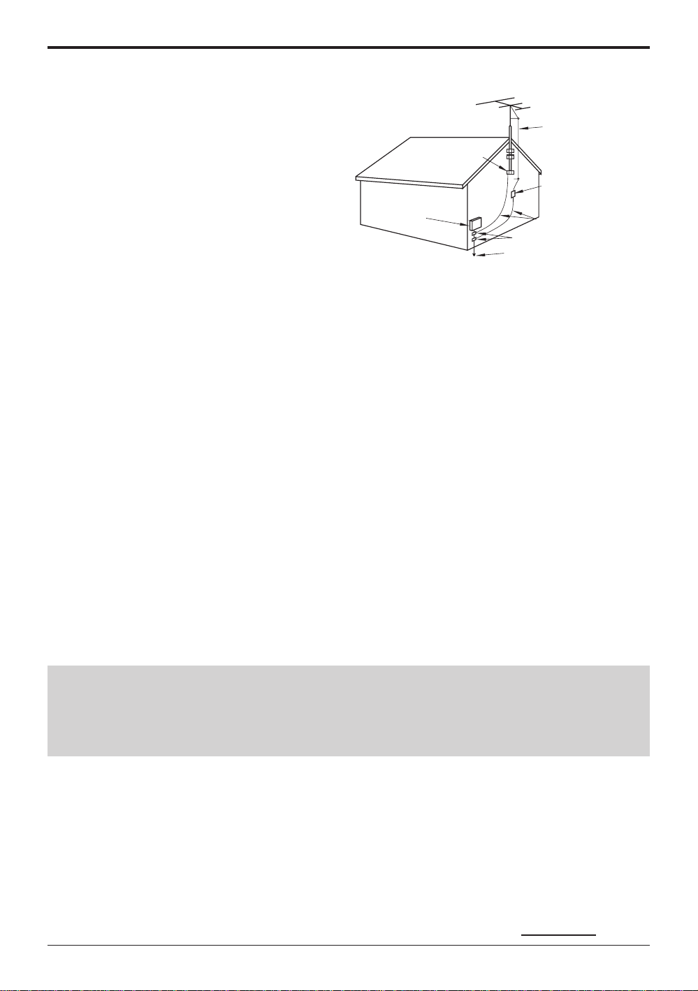
17) If an outside antenna is connected to the
television
equipment, be sure the antenna system
is grounded so as to provide some protection
against voltage surges and built up static
charges. In the U.S. Selection 810-21 of the
National Electrical Code provides information
with respect to proper grounding of the mast and
supporting structure, grounding of the lead-in wire
to an antenna discharge unit, size of grounding
conductors, location of antenna discharge unit,
connection to grounding electrodes, and
requirements for the grounding electrode.
18) An outside antenna system should not be located
in the vicinity of overhead power lines or other
EXAMPLE OF ANTENNA
GROUNDING AS PER (NEC)
NATIONAL ELECTRICAL
CODE
GROUND
CLAMP
ELECTRIC
SERVICE
EQUIPMENT
ANTENNA
LEAD-IN WIRE
ANTENNA
DISCHARGE UNIT
(NEC SECTION 810-20)
GROUNDING CONDUCTORS
(NEC SECTION 810-21)
GROUND CLAMPS
POWER SERVICE GROUNDING
ELECTRODE SYSTEM
(NEC ART 250, PART H)
electric light or power circuits, or where it can fall into such power lines or circuits. When installing an
outside antenna system extreme care should be taken to keep from touching such power lines or circuits
as contact with them might be fatal.
19) Unplug this LCD TV from the wall outlet, and refer servicing to qualified service personnel under the
following conditions:
a. When the power cord or plug is damaged or frayed.
b. If liquid has been spilled into the LCD TV.
c. If the LCD TV has been exposed to rain or water.
d. If the LCD TV does not operate normally by following the operating instructions.
Adjust only those controls that are covered by the operating instructions as improper adjustment of other
controls may result in damage and will often require extensive work by a qualified technician to restore
the LCD TV to normal operation.
e. If the LCD TV has been dropped or the cabinet has been damaged.
f. When the LCD TV exhibits a distinct change in performance - this indicates a need for service.
20) When replacement parts are required, be sure the service technician to use replacement parts specified by
the manufacturer that have the same characteristics as the original part. Unauthorized substitutions may
result in fire, electric shock, or other hazards.
21) WARNING: TO REDUCE THE RISK OF FIRE OR ELECTRIC SHOCK, DO NOT EXPOSE THIS
APPARATUS TO RAIN OR MOISTURE.
22) CAUTION: TO PREVENT ELECTRIC SHOCK DO NOT USE THIS PLUG WITH A RECEPTACLE OR
OTHER OUTLET UNLESS THE BLADES CAN BE FULL Y INSERTED TO PREVENT BLADE EXPOSURE.
23) CAUTION: USE WITH OTHER STAND MAY RESULT IN INSTABILITY CAUSING POSSIBLE INJURY.
24) CAUTION: DANGER OF EXPLOSION IF BATTERY IS INCORRECTLY REPLACED. REPLACE ONLY
WITH THE SAME OR EQUIVALENT TYPE.
NOTE: • This equipment is designed to operate in the U.S.A. and other countries where the broadcasting
system and AC house current is exactly the same as in the U.S.A.
The marking or retained image on the LCD panel resulting from fixed image use is not an operating
•
defect and as such is not covered by Warranty. This product is not designed to display fixed image
patterns for extended periods of time.
■
Important Information Regarding Use of Video Games, Computers, Captions or Other Fixed Image Displays.
The extended use of fixed image program material can cause a permanent "shadow image" on the LCD panel.
This background image is viewable on normal programs in the form of a stationary fixed image. This type of
irreversible LCD panel deterioration can be limited by observing the following steps:
A. Reduce the brightness/contrast setting to a minimum viewing level.
B. Do not display the fixed image for extended periods of time.
C. Turn the power off when not in actual use.
■
This product utilizes tin-lead solder, and has a fluorescent lamp containing a small amount of mercury . Disposal of
these materials may be regulated in your community due to environmental considerations. For disposal or recycling
information please contact your local authorities, or the Electronics Industries Alliance:
www.eiae.org.
3
Page 4

Dear Panasonic Customer
Welcome to the Panasonic family of customers.
We hope that you will have many years of enjoyment from your new LCD TV.
To obtain maximum benefit from your set, please read these instructions before
making any adjustments, and retain them for future reference.
Retain your purchase receipt, and record the model number and serial number
of your set in the space provided on the rear cover of these instructions.
Federal Communication Commission Information
This equipment has been tested and found to comply with the limits for a TV Broadcast Receiver, pursuant
to Part 15 of the FCC Rules. These limits are designed to provide reasonable protection against harmful
interference in a residential installation. This equipment generates, uses and can radiate radio frequency
energy and, if not installed and used in accordance with the instructions, may cause harmful interference to
radio communications. If this equipment does cause or receive interference, which can be determined by
turning equipment off and on, the user is encouraged to try to correct the interference by one of the following
measures:
Reorient or relocate the TV antenna.
Increase the separation between TV and other equipment.
Connect TV into separate outlet from other equipment.
Consult the dealer or an experienced radio/TV technician for help.
FCC Caution: Any changes or modifications not expressly approved by the party responsible for compliance
could void the user’s authority to operate this equipment.
4
Page 5

Table of Contents
Important Safety Instructions .............................. 2
Table of Contents.................................................. 5
Installation ............................................................. 6
SUPPLIED ACCESSORIES ................................ 6
Remote control battery installation ...................... 7
Maintenance .......................................................... 7
Connections .......................................................... 8
Connecting the Antenna Cable to the Antenna Terminal ....
Antenna cover removal and fitting ....................... 8
Antenna / Cable Connection................................ 8
How to connect the input terminals ................... 10
Cable cover removal and fitting ......................... 12
Connecting Headphones / Earphones............... 12
Power ON / OFF................................................... 13
Connecting the Plug to the Wall Outlet.............. 13
How to Turn the Power On ................................ 13
Playing a VCR or other peripheral equipment ... 14
Basic Controls..................................................... 15
Flow Chart of MENU............................................16
Tuning channels
(Automatic channel programming) .................. 18
Tuning channels
(Manual channel programming)........................19
Picture Adjustments ........................................... 20
Audio Adjustments ............................................. 21
8
Lock Feature........................................................ 22
Closed Captions.................................................. 26
Customizing the VIDEO INPUT labels ............... 27
3D Y/C FILTER / COLOR MATRIX....................... 27
ASPECT Controls................................................ 28
Troubleshooting .................................................. 29
Specifications...................................................... 31
5
Page 6
Installation
Receiver Location
Locate for comfortable viewing. A void placing where sunlight or other bright light (including reflections) will fall on the screen.
Use of some types of fluorescent lighting can reduce remote control transmitter range.
Adequate ventilation is essential to prevent internal component failure. Keep away from areas of excessive heat or moisture.
Optional External Equipment
The Video/Audio connection between components can be made with shielded video and audio cables. For
best performance, Antenna cables should utilize 75 ohm coaxial shielded wire. Cables are available from
your dealer or electronic supply store.
Before you purchase any cables, be sure you know what type of output and input connectors your various
components require. Also determine the length of cable you’ll need.
For optimum quality picture
When the LCD is exposed to light from outdoors or lighting fixtures, high-contrast pictures may not be displayed
clearly. Turn off florescent lamps near the LCD and place in a location not exposed to outdoor light.
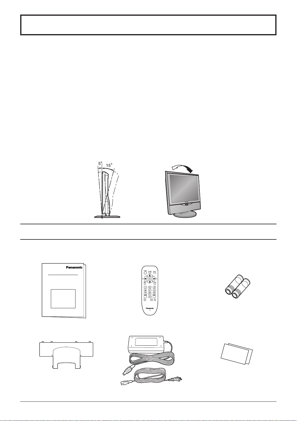
How to use the LCD stand
Adjust the stand to your desired angle. The stand angle can be adjusted between 5 ° forward to 15 ° back.
SUPPLIED ACCESSORIES
Check the accessories before installations.
Operating Instruction book
•
Tuner Cable Cover
•
Remote Control Transmitter
•
AC Adaptor & AC Cord
•
A1
4L
-1
TH
Batteries for the Remote
•
Control Transmitter
(2 × AA size)
Warranty Card
•
[
The illustration shows only a basic view; actual appearance may differ.]
6
Page 7
Installation
Remote control battery installation
Replacing batteries
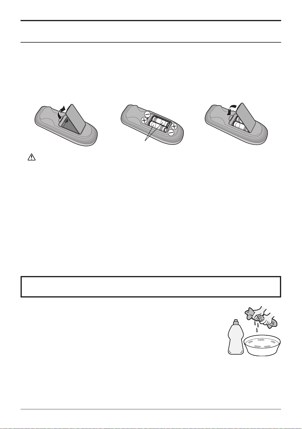
Replace batteries by following the steps below:
Requires two AA batteries.
1. Open the battery cover.
Precaution on battery use
Incorrect installation can cause battery leakage and corrosion that will damage the remote control
transmitter.
Observe the following precautions:
1. Always use new batteries when replacing the old set.
2. Do not attempt to charge, short-circuit, disassemble, heat or burn used batteries.
3. Battery replacement is necessary when remote control acts sporadically or stops operating this unit.
2. Install the batteries as shown
in the battery compartment.
(Polarity + or – must match the
markings in the compartment).
Two AA size
3. Replace the cover.
Notes:
Do not drop, apply shock to or step on the remote control.
•
Do not spill water on the remote control.
•
Do not place objects between the remote control and remote control receiver.
•
Do not use remote controls for other equipment at the same time.
•
If the TV does not operate even when operating the remote control from a close range, it is time to
•
replace the batteries.
Refer to the label on back of the remote control for directions on replacing batteries.
Maintenance
To clean this unit, wipe with a soft, dry cloth.
If the surfaces are extremely dirty, use a soft cloth dipped in a soap and
water solution or a weak detergent solution.
• Use eyeglass cleaner to remove stubborn dirt from the LCD.
• Never use alcohol, paint thinner or benzine to clean this unit.
• Before using a chemically treated cloth, read the instructions that came
with the cloth carefully.
CAUTION :
If water or similar substances get inside the monitor via the liquid crystal panel surface, a malfunction may result.
Mild
detergent
7
Page 8

Connections
Connecting the Antenna Cable to the Antenna T erminal
Antenna Connection - For proper reception of VHF/UHF channels, an external antenna is required. For best
reception an outdoor antenna is recommended. Antenna Mode must be set to TV.
VHF Antenna
UHF Antenna
ANT
Mixer
75 Ohm
Coaxial Cable
ANT
Antenna Terminal
(ANT or VHF/UHF)
Coaxial Antenna Plug
Antenna cover removal and fitting
CT-L1400
Removal
1
2
Fitting
1
2
Note:
To avoid interference appearing on the screen, do not bundle the antenna wire and AC adapter wire together.
1.Grasp the cover at the
bottom end and initially
remove by pulling slightly
toward yourself.
2.Slowly pull out in the
downward direction.
1.Insert the claws (at 4
points) at the top end.
2.Push the claws in (at 4
points) at the bottom
end.
CT-L2000
Removal
Fitting
1
1.
Grasp the opening and initially
pull the cover slightly towards
yourself to disengage the
1
2
2
claws (at 2 points on both the
left and right).
2.Slowly pull out in the
downward direction.
1.Insert the claws (at 4
points) at the top end.
2.Push the claws in (at 4
points) at the bottom
end.
Antenna / Cable Connection
Incoming 75 Ohm Cable from Home Antenna / Cable Company
F-Type Antenna Adapter (not supplied)
ANT (VHF/UHF)
on the Back of the TV
Cable Connection - For reception of cable channels (01 - 125) connect the cable supplied by your local cable company.
Antenna Mode must be set to CABLE. (Refer to Antenna Mode section.)
Note:
Certain cable systems offset some channels to reduce interference or have Premium (scrambled) channels. A cable
converter box is required for proper reception. Check with your local Cable company for its compatibility requirements.
8
Page 9

Connections
Antenna Connection (Cable Box, no VCR)
Use this configuration when connecting the TV to a cable TV system using a Cable Box.
ANT
ANTENNA TERMINAL
CABLE BOX
ANT
(ANT or VHF/UHF)
ON THE BACK OF
THE TV
OUTPUT INPUT
TERMINALS ON THE BACK OF
THE CABLE BOX
Connect the cable from the Output
terminal on the back of the Cable
Box to the ANTENNA terminal on
the back of the TV.
Incoming Cable from
Antenna or Cable TV
System
Antenna Connection (Cable Box, and VCR)
Use this configuration when connecting the TV to a cable TV system using a Cable Box and VCR.
CABLE BOX
ANT
OUTPUT INPUT
TERMINALS ON THE BACK OF
THE CABLE BOX
ANT
ANTENNA TERMINAL
(ANT or VHF/UHF)
ON THE BACK OF
THE TV
Connect the cable from the
Output terminal on the back
of the Cable Box to the
Antenna Input terminal on
Connect the cable from the
antenna or cable system to the
Input terminal on the back of the
CABLE BOX.
the back of the VCR.
VCR
Incoming Cable from
Antenna or Cable TV
System
TO VCR
Connect the
cable from the
Antenna Output
terminal on the
back of the VCR
to the Antenna
terminal (ANT or
VHF/UHF) on the
back of the TV.
ANT INPUT
ANT OUTPUT
S VIDEO
OUTPUT
VIDEO
L-AUDIO-R
Note: When the antenna cable is connected to the TV antenna terminal via a cable box or VCR, set the TV
channel to CH3 or CH4, cable. This does not apply when signal is input from VIDEO INPUT.
9
Page 10

Connections
How to connect the input terminals
Connect VCR and other peripheral equipment
(DVD/STB)
VIDEO
Y
L
P
B
AUDIO
P
R
R
COMPORNENT VIDEO INPUT
S-VIDEO
S-VIDEO
VIDEO
VIDEO
L
L
AUDIO
AUDIO
R
R
1
2
INPUT
DC IN 15V
ANT
VIDEO
Y
L
P
B
AUDIO
R
P
R
COMPORNENT VIDEO INPUT
VIDEO
L
AUDIO
R
1
S-VIDEO
VIDEO
L
AUDIO
R
2
S-VIDEO
INPUT
Audio
OUT
R
L
AUDIO
VIDEO
S-VIDEO cable
VIDEO
AUDIO
COMPONENT VIDEO OUT
PrPbY
Connect the
S-VIDEO or
VIDEO Terminal.
Audio
OUTRL
Video
OUT
S-Video
OUT
(Super-VHS VCR)
Notes:
(1) When a monaural VCR is used, connect the monaural audio cable to the AUDIO-L (Left) terminal.
(2) Similar connections are available at the INPUT terminals.
Select the desired VIDEO input position by pushing the TV/VIDEO button. (See page 14)
(3) When connecting VCRs, priority is given to the S- Video cable when the S- Video input terminal and the
video input terminal are connected at the same time.
10
Page 11
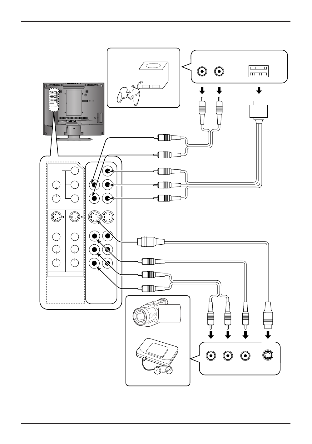
Connect CAMCORDER and VIDEO GAME CONSOLE
Connections
VIDEO
Y
L
P
B
AUDIO
P
R
R
COMPORNENT VIDEO INPUT
S-VIDEO
S-VIDEO
VIDEO
VIDEO
L
L
AUDIO
AUDIO
R
R
1
2
INPUT
DC IN 15V
ANT
VIDEO
Y
L
P
B
AUDIO
P
R
R
COMPORNENT VIDEO INPUT
S-VIDEO
S-VIDEO
VIDEO GAME CONSOLE
Audio
OUT
R
L
AUDIO
cable
COMPONENT
VIDEO cable
COMPONENT VIDEO OUT
VIDEO
VIDEO
L
L
AUDIO
R
1
INPUT
AUDIO
R
2
AUDIO cable
VIDEO cable
CAMCORDER
Audio
OUTLR
Video
OUT
S-Video
OUT
VIDEO GAME CONSOLE
Notes:
S-VIDEO cable
When connecting video cables, priority is given to the S-Video cable when the S-Video input terminal
•
and the video input terminal are connected at the same time.
Please make inquiries to the VIDEO GAME PLAYER manufacture concerning component cables to
•
connect with video games.
11
Page 12
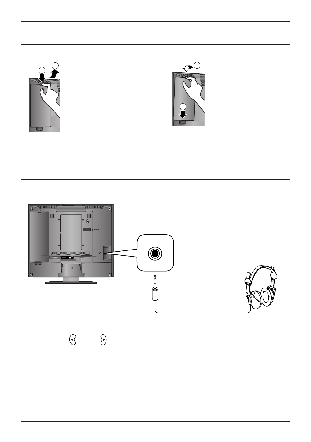
Connections
Cable cover removal and fitting
Removal
1.Disengage the claws at the
2
1
Note:
Depending on the type of cable used it may not be possible to close the cover. In such cases the cable may be
routed through the antenna cover.
uppermost end.
2.Slowly pull out in the
upward direction.
Fitting
1
2
1.Insert the claws (at 2 points)
at the bottom.
2.Push in the TOP.
Connecting Headphones / Earphones
Connect headphones / earphones as follows.
DC IN 15V
ANT
(M3 plug)
Use Volume Up or Down button to control volume level. (See page 15)
12
(Optional)
Page 13
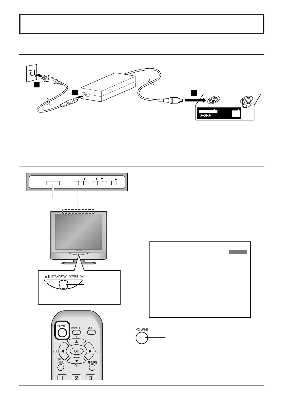
Power ON / OFF
Connecting the Plug to the Wall Outlet
2
3
1
2
DC IN 15V
Note:
The TV and AC adaptor will still consume some power as long as the power cord is still inserted into the wall outlet.
•
Be sure to use the power cord and AC adaptor included in the accessories.
•
Usage of AC adapters other than specified may cause malfunctions.
•
ANT
How to Turn the Power On
POWER
Main Power switch
TV/VIDEO VOLUME CHANNEL
Press the Main POWER switch on the TV to turn the set on.
POWER-ON: Green
When the set is on or in standby mode press the Main
POWER switch on the TV to turn the set off.
POWER-OFF: No light
Example: The screen below is displayed for a while after
the TV is turned on. (setting condition is an
example.)
4 : 3
CH 6
STEREO
SAP
MONO
Power Indicator
Remote control
signal sensor
Press the POWER button on the remote
control to turn the TV off: Red (standby)
Press the POWER button on the remote
control to turn the TV on: Green
13
Page 14
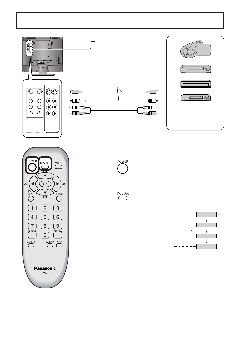
Playing a VCR or other peripheral equipment
TV
VIDEO1
COMPONENT
VIDEO2
VIDEO
Y
L
P
B
AUDIO
P
R
R
COMPORNENT VIDEO INPUT
S-VIDEO
S-VIDEO
VIDEO
VIDEO
L
L
AUDIO
AUDIO
R
R
1
2
INPUT
S-VIDEO
VIDEO
L
AUDIO
R
1
INPUT
DC IN 15V
S-VIDEO
VIDEO
L
AUDIO
R
2
Confirming connections
Confirm that the TV is in standby
mode.
ANT
To S-Video output
Camcorder
VCR
or Video output
Laser Disc Player
DVD player
This equipment can also be
T o Audio output
connected to the rear
terminals. (See page 10,1 1)
Turning the power on and switching input modes
1
Turn the TV on.
14
2
The input mode changes each time
this button is pressed.
When playing
•
a VIDEO
When playing
•
a DVD
Note:
When the remote control is unavailable, input modes can also be
switched using the TV/VIDEO button on the TV set.
Operate the connected equipment.
3
Page 15
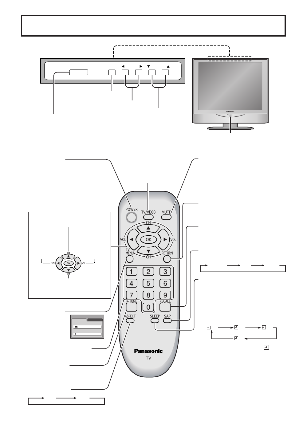
Basic Controls
30 60
0
90
<Top Side Controls>
POWER
TV/VIDEO VOLUME CHANNEL
TV/VIDEO button
Volume Up/Down
Channel Up/Down
Main POWER switch
First press the POWER switch to turn the set on.
Operate your Remote control pointed to the Remote control sensor
(Within about 6 meters in front of the TV set.)
Power button
Press to turn this set ON or OFF.
(See page 13)
Note:
TV/VIDEO button
The input mode
changes each time
this button is pressed.
The LCD TV’s power cord must
first be plugged into the wall
outlet and then turned on at the
Main POWER switch.
Changes to the next channel up
Moves cursor upward during menu
mode.
Reduces volume
Moves cursor to
the left during
menu mode.
Increases volume
Moves cursor to
the right during
menu mode.
Remote control sensor
MUTE button
Press to mute the sound.
Press again to reactivate sound.
Sound is also reactivated when
power is turned off or volume level
is changed.
RETURN button
Press to return to the previous
screen.
RECALL button
Press to display time, channel, sleep
timer and other options.
SAP button
Selects Audio mode (See page 21).
STEREO SAP MONO
Changes to the next channel down
Moves cursor downward during menu
mode.
MENU button
Press to display
MENU screen,
press again to
clear.
Direct program number
Selection buttons
R-TUNE button
Switches to previously viewed
channel or video mode.
ASPECT button
SLEEP button
The LCD TV may be preset to switch
to stand-by after a fixed period. The
setting changes to 30 minutes, 60
minutes, 90 minutes and 0 minutes
MENU
ADJUST
PICTURE ADJUST
AUDIO ADJUST
PICTURE
AUDIO
SET UP
(SLEEP timer cancelled) each time
this button is pressed.
When 3 minutes remain, “
3 ” will
flash. The SLEEP timer is cancelled
if a power interruption occurs.
Before the timer automatically turns
the power off, the remaining time will
blink on the screen (“3” for 3 minutes,
“2” for 2 minutes and “1” for 1 minute
4 : 3
16 : 9
before the power goes off).
15
Page 16
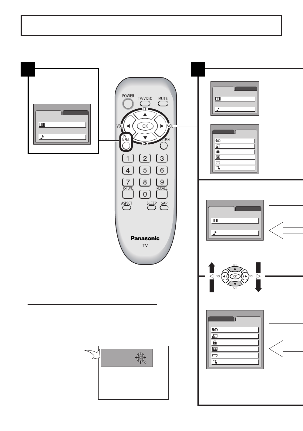
Flow Chart of MENU
MENU
ADJUST SET UP
LANGUAGE
PROGRAM CH
LOCK
CLOSED CAPTION
INPUT LABEL
OTHER ADJUST
MENU
ADJUST
PICTURE
AUDIO
SET UP
PICTURE ADJUST
AUDIO ADJUST
MENU
ADJUST SET UP
LANGUAGE
PROGRAM CH
LOCK
CLOSED CAPTION
INPUT LABEL
OTHER ADJUST
MENU
ADJUST
PICTURE
AUDIO
SET UP
PICTURE ADJUST
AUDIO ADJUST
All adjustments and setting functions equipped in this set can be made using the menu buttons.
The menu screen is composed of 2 menus, the ADJUST menu and the SET UP menu.
1
Press to display MENU
screen, press again to
clear.
MENU
ADJUST
PICTURE ADJUST
AUDIO ADJUST
SET UP
PICTURE
AUDIO
2
MENU selection
or
Please refer to the On Screen Help
An On Screen Help box is displayed whenever a menu is displayed
on the TV . This Help box indicates which keys on the remote control
are used to navigate the menu shown, see above for descriptions
of button functions.
16
ON SCREEN HELP
‘Instruction’ box
MANUAL PROGRAM
ENTER CHANNEL
DELETE
121
CH SELECT
ADD
RETURN
[ for TC-1400 ]
Page 17
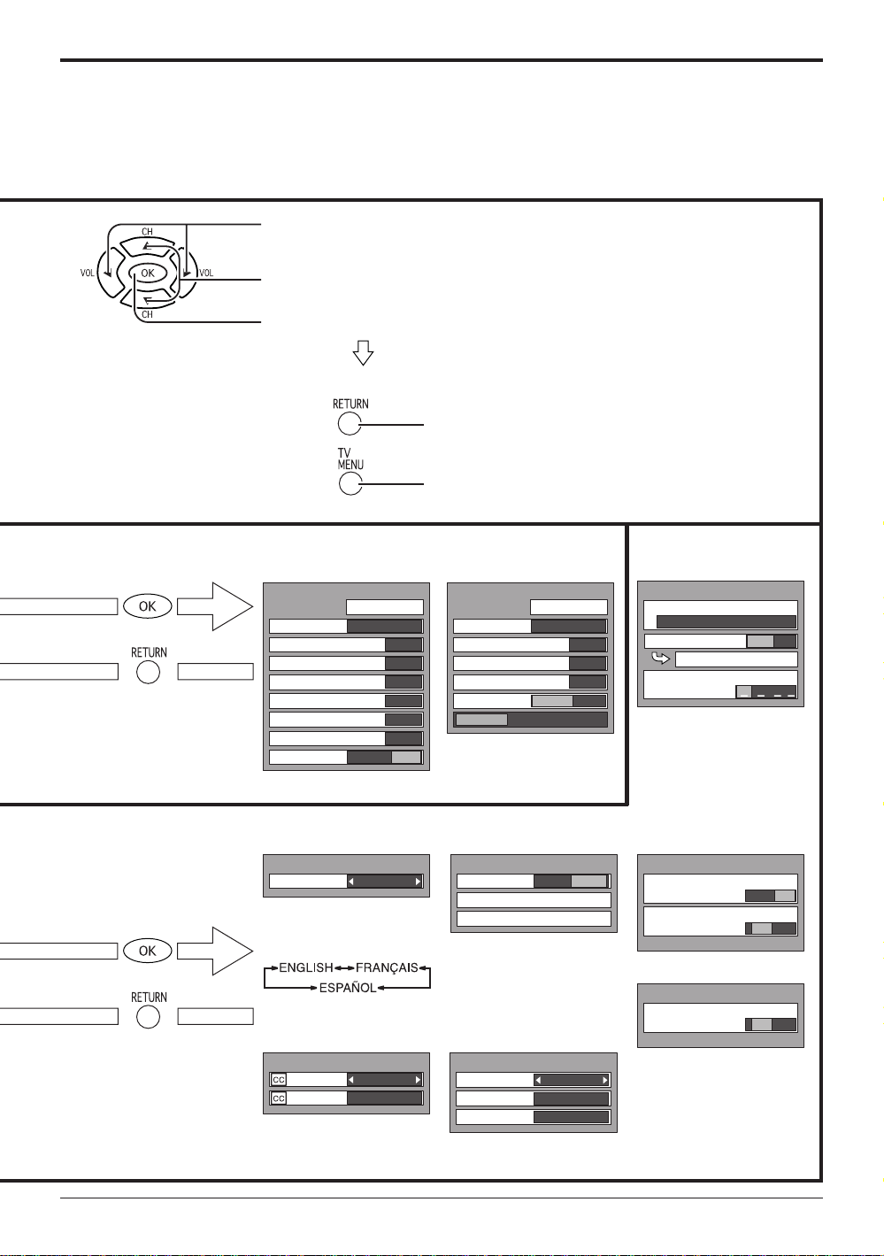
Flow Chart of MENU
LOCK
BLOCK PROGRAMS
:
STATUS
U. S. MOVIES
CHANGE SETTING
ENTER CODE FIRST
OFF ON
OTHER ADJUST
3D Y/C FILTER
OFF ON
COLOR MATRIX
SD HD
Press to select the desired MENU (ADJUST or SET UP).
Press to select each item.
Press to display each adjustment screen.
Proceed to the adjustment.
To return to previous screen :
•
To end adjustments :
•
Press to display each
adjustment screen.
Press the RETURN
button to return to
previous screen.
Press to display each
adjustment screen.
Press the RETURN
button to return to
previous screen.
TO PICTURE ADJUST
menu
PICTURE ADJUST
PIC MODE
BACK LIGHT
PICTURE
BRIGHTNESS
COLOR
TINT
SHARPNESS
AI PICTURE
NORMAL
STANDARD
+ 30
0
0
0
0
0
COOLCOOL
OFF ON
OFF ON
(See page 20)
TO LANGUAGE
LANGUAGE
LANGUAGE
ENGLISH
Allows you to select the
language used for On
Screen Displays.
TO CLOSED
CAPTION
CLOSED CAPTION
ON MUTE
MODE
NO
OFF
(See page 26)
Press to return.
Press to exit from the MENU screen.
This returns the set to the normal viewing condition.
TO AUDIO ADJUST
menu
AUDIO ADJUST
MODE
BASS
TREBLE
BALANCE
SURROUND
STEREO SAP MONO
NORMAL
AUTO
OFF ON
+ 5
+ 2
0
TO LOCK
selection screen
(See page 22 - 25)
(See page 21)
TO PROGRAM
CHANNELS
PROGRAM CHANNELS
MODE
TV
AUTO PROGRAM
MANUAL PROGRAM
CABLE
TO OTHER ADJUST
screen
(See page 18,19)
[ for TC-2000 ]
OTHER ADJUST
TO INPUT LABEL
COLOR MATRIX
SD HD
selection screen
INPUT LABEL
VIDEO1
VIDEO2
COMPONENT
VIDEO1
VIDEO2
COMPONENT
[ for TC-1400 ]
(See page 27)
(See page 27)
17
Page 18
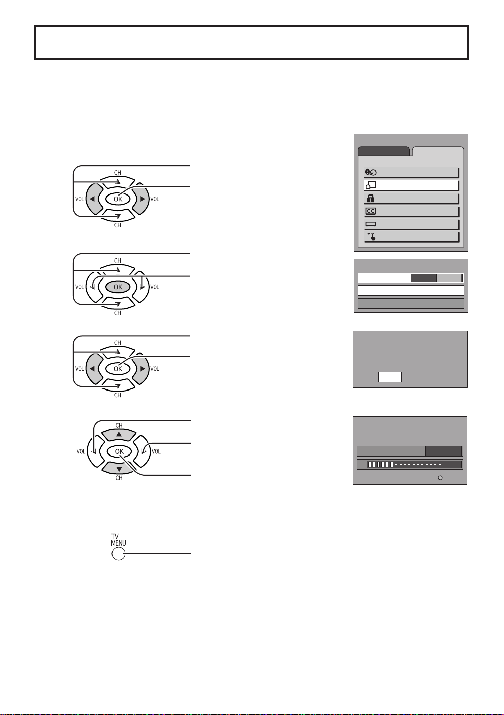
T uning channels (Automatic channel programming)
Automatically scans all TV channels and stores them in memory.
Turn the Power on and press the TV/VIDEO button to display the TV channel.
1
Press the MENU button to display the MENU screen and select SET UP.
2
Press to select PROGRAM CH.
Press to display the PROGRAM
CHANNELS screen.
Press to select MODE.
3
Press to select TV or CABLE.
Press to select AUT O PROGRAM.
4
Press to display the confirmation
screen.
5
Press to select YES.
Press to select NO.
MENU
ADJUST SET UP
LANGUAGE
PROGRAM CH
LOCK
CLOSED CAPTION
INPUT LABEL
OTHER ADJUST
PROGRAM CHANNELS
MODE
AUTO PROGRAM
MANUAL PROGRAM
AUTO PROGRAM
Activate
AUTO PROGRAM
In "AUTO PROGRAM"
CHANNEL 59
TV
"AUTO PROGRAM?"
YES NO
CABLE
If YES selection
press to run AUTO PROGRAM.
Channels will automatically advance until all channels have been
scanned. Channel numbers with a video signal present will be stored
in the Channel Scan Memory.
Press to exit from the MENU screen.
This returns the set to the normal viewing condition.
Notes:
When buttons are pressed with AUTO PROGRAM running, the TV set will return to normal viewing.
•
(Channels searched up to this point are added.)
After AUTO PROGRAM is finished, the lowest channel number added will be received.
•
When there are no receivable channels, channel 69 is displayed for TV and channel 125 is displayed
•
for cable TV.
18
MENU
STOP
Page 19
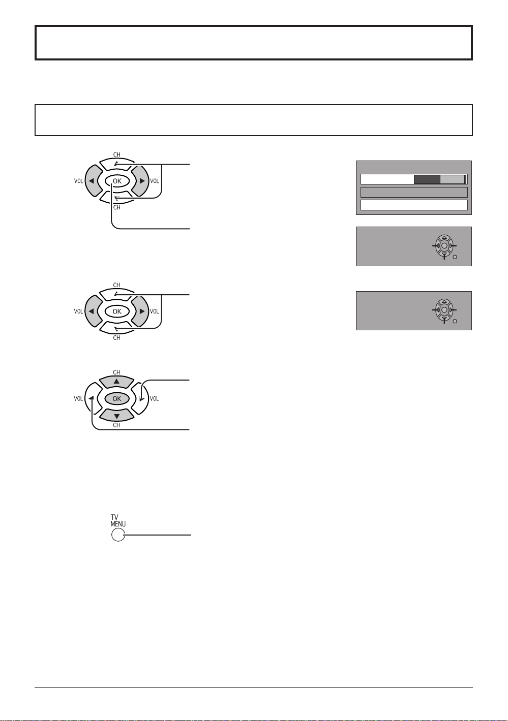
Tuning channels
(Manual channel programming)
Use this setting when changing setting of receiving channels or changing the channel display .
Turn the TV on and select the broadcast channel. Follow the steps on the previous page to display the
PROGRAM CHANNELS screen.
1
Press to select MANUAL PROGRAM.
Press to display the MANUAL
PROGRAM screen.
Adding or deleting channels
2
3
Press to select channel
(or number keys).
Press to add channels to memory (Channel
number turns blue).
Press to delete channels from memory
(Channel number turns yellow).
PROGRAM CHANNELS
MODE
AUTO PROGRAM
MANUAL PROGRAM
MANUAL PROGRAM
ENTER CHANNEL
MANUAL PROGRAM
ENTER CHANNEL
TV
121
121
CABLE
DELETE
CH SELECT
DELETE
CH SELECT
ADD
RETURN
ADD
RETURN
Repeat steps 2 and 3 to continue adding or deleting channels.
4
Press to exit from the MENU screen.
This returns the set to the normal viewing condition.
19
Page 20
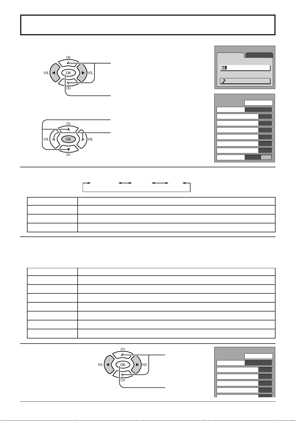
Picture Adjustments
Press the MENU button to display the MENU screen and select ADJUST.
1
Press to select PICTURE ADJUST.
Press to display the PICTURE
ADJUST screen.
2
Press to select the menu to adjust.
Select the desired level by looking at
the picture behind the menu.
NORMAL is displayed at default.
PICTURE MODE is stored for TV, VIDEO1, VIDEO2 and COMPONENT individually.PIC MODE
CINEMA VIVIDSTANDARD
MODE
STANDARD
CINEMA
VIVID
Displays standard image.
Ideal for watching movies in a dark room.
Displays a clear screen with contrast of light and dark.
Function
MENU
ADJUST
PICTURE
PICTURE ADJUST
AUDIO
AUDIO ADJUST
PICTURE ADJUST
PIC MODE
BACK LIGHT
PICTURE
BRIGHTNESS
COLOR
TINT
SHARPNESS
AI PICTURE
NORMAL
STANDARD
OFF ON
SET UP
+ 30
0
0
0
0
0
COOLCOOL
OFF ON
BACK LIGHT, PICTURE, BRIGHTNESS, COLOR, TINT, SHARPNESS, AI PICTURE
Y ou can change the level of each Item (BACK LIGHT , PICTURE, BRIGHTNESS, COLOR, TINT , SHARPNESS
and AI PICTURE) for each MENU (STANDARD, CINEMA, and VIVID ) according to your personal preference.
Item
BACK LIGHT
PICTURE
BRIGHTNESS
COLOR
TINT
SHARPNESS
AI PICTURE
To reset to standard setting :
•
Luminance of the back light is adjusted.
Selects proper brightness and density for the room.
Adjusts for easier viewing of dark pictures such as night scenes.
Adjusts the level of color.
Adjusts for flesh tone color.
Adjusts the degree of sharpness.
Displays black and white colors more clearly when turned ON.
Function
Press to Select
NORMALIZE.
Press OK.
PICTURE ADJUST
PIC MODE
BACK LIGHT
PICTURE
BRIGHTNESS
COLOR
NORMALIZE
STANDARD
20
+ 5
0
0
0
Page 21
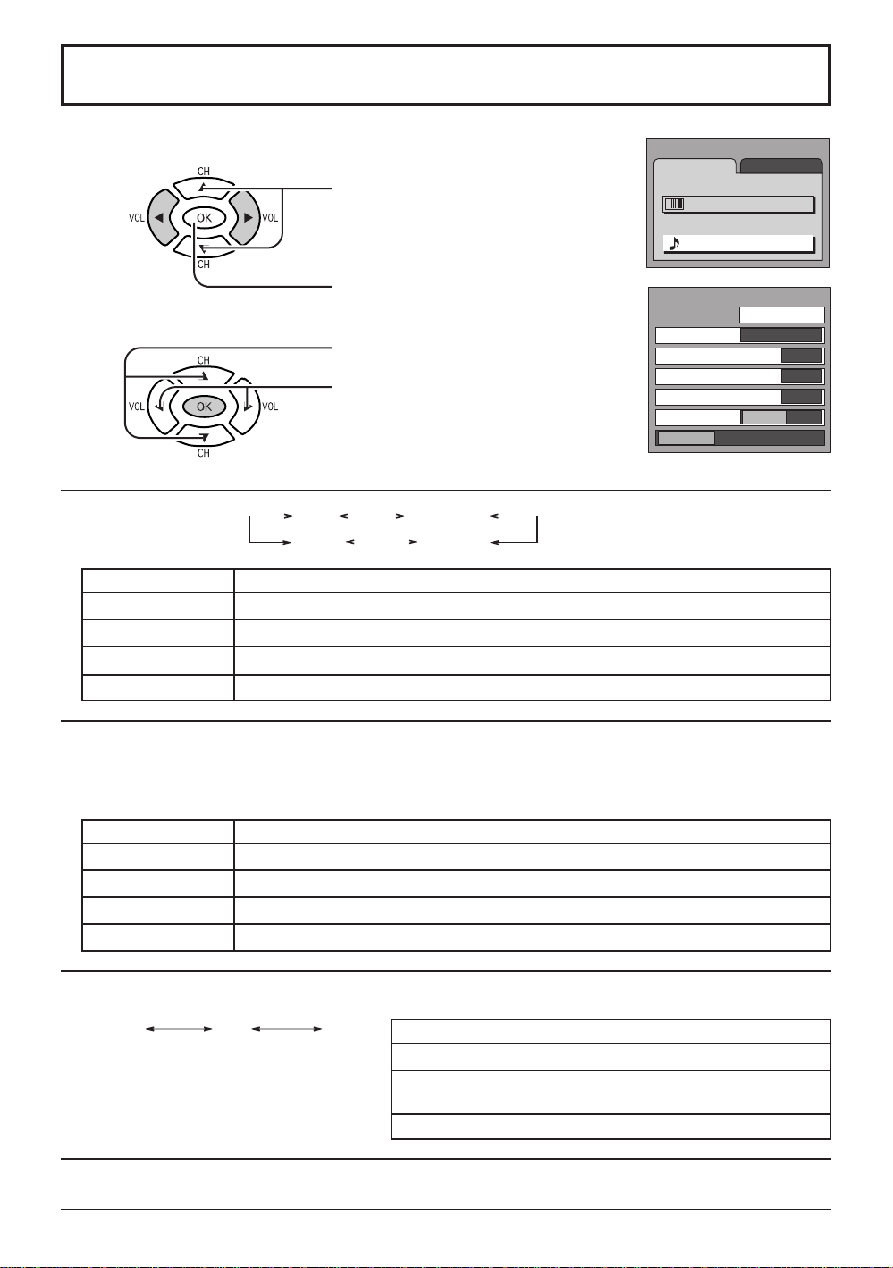
Audio Adjustments
Press the MENU button to display the MENU screen and select ADJUST.
1
Press to select AUDIO ADJUST.
Press to display the AUDIO ADJUST
screen.
2
MODE
STANDARD
DYNAMIC
MODE
AUTO
MUSIC
Automatically adjusts quiet sound and loud sound for ease of listening.
Emits the original sound.
Gives contrast to sound.
For programs consisting mainly of music. Enhances high sounds (around 4 kHz).
Press to select the menu to adjust.
Select the desired level by listening
to the sound.
NORMAL is displayed at default.
AUTO
MUSIC
STANDARD
DYNAMIC
Function
MENU
ADJUST
PICTURE ADJUST
AUDIO ADJUST
AUDIO ADJUST
MODE
BASS
TREBLE
BALANCE
SURROUND
STEREO SAP MONO
SET UP
PICTURE
AUDIO
NORMAL
AUTO
OFF ON
+ 5
+ 2
0
BASS, TREBLE, BALANCE, SURROUND
You can change the level of each Item (BASS, TREBLE, BALANCE and SURROUND) for each MODE
(AUTO, STANDARD, DYNAMIC and MUSIC) according to your personal preference.
Item
BASS
TREBLE
BALANCE
SURROUND
Selecting STEREO/SAP/MONO
Note:
Red display : With signal
White display : No signal
White display : MONO
To reset to standard setting : See previous page.
•
Adjusts low sounds
Adjusts high sounds
Adjust left and right volume
To enjoy a concert hall effect, turn SURROUND to ON when stereo is playing.
SAP MONOSTEREO
MODE
STEREO
SAP
MONO
Function
Function
Two channel Audio reception.
Second Audio Programming
(typically used for bilingual audio).
Use when stereo signal is weak.
21
Page 22
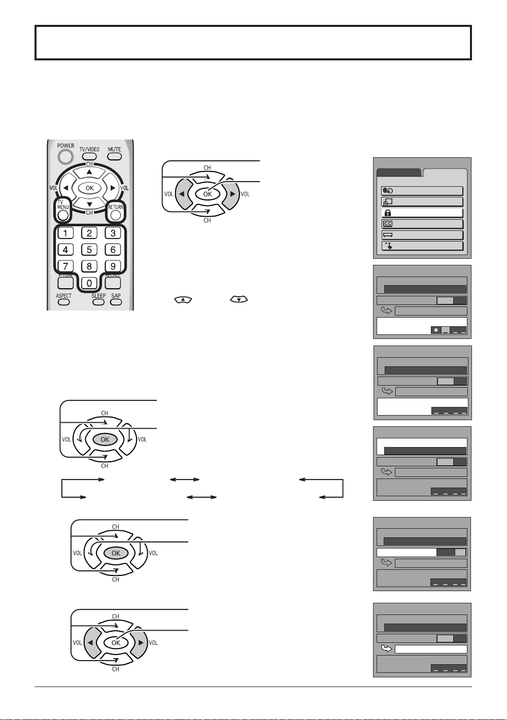
Lock Feature
MENU
ADJUST SET UP
LANGUAGE
PROGRAM CH
LOCK
CLOSED CAPTION
INPUT LABEL
OTHER ADJUST
LOCK
BLOCK PROGRAMS
:
STATUS
U. S. TV PROGRAMS
CHANGE SETTING
CHANGE CODE
OFF ON
LOCK
BLOCK PROGRAMS
:
STATUS
U. S. MOVIES
CHANGE SETTING
ENTER CODE FIRST
OFF ON
LOCK
BLOCK PROGRAMS
:
STATUS
U. S. TV PROGRAMS
CHANGE SETTING
CHANGE CODE
OFF ON
LOCK
BLOCK PROGRAMS
:
STATUS
U. S. TV PROGRAMS
CHANGE SETTING
CHANGE CODE
OFF ON
In the United States, the V-CHIP consists of two rating systems, which are MPAA
(MOTION PICTURE) and TV PARENT AL GUIDELINES. Its function is to block programs
by the rating data in the XDS data packets sent from broadcasting stations. The user
can select which rating programs should be blocked by the LOCK MENU options.
Press the MENU button to display the MENU screen and select SET UP.
Press to select LOCK.
Press to display the
LOCK screen.
Input code
Enter any 4-digit number as a password.
These numbers will be needed when
deactivating the LOCK function.
While entering a code, by pressing the
up
input a new code again.
After entering your secret code for the first time, the onscreen display will
change to CHANGE CODE. And you can change the Input code.
Note: Use a code that is easy to remember and record it in a safe place.
Selecting broadcasts to lock.
1
Press to select BLOCK PROGRAMS:.
or down buttons you can
LOCK
BLOCK PROGRAMS
U. S. TV PROGRAMS
STATUS
CHANGE SETTING
CHANGE CODE
:
OFF ON
2
3
22
U.S. MOVIES
Press to select U.S MOVIES, U.S. TV
PROGRAMS, CANADIAN ENGLISH
or CANADIAN FRENCH.
U.S. TV PROGRAMS
CANADIAN ENGLISHCANADIAN FRENCH
Press to select STATUS.
Press to select ON or OFF.
Press to select CHANGE SETTING.
Press to display the next screen.
Page 23
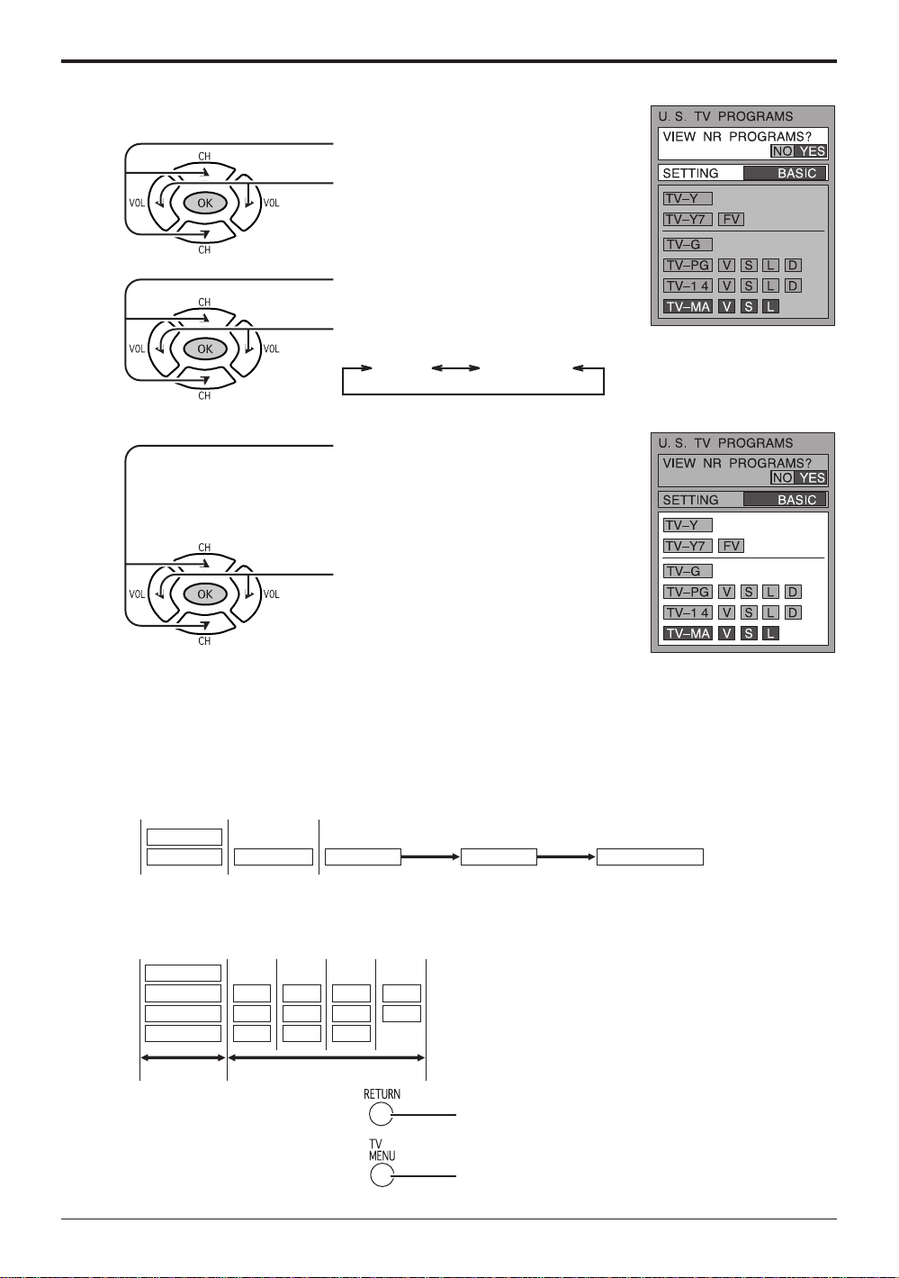
for U.S.TV PROGRAM to lock
Lock Feature
1
2
3
Press to select VIEW NR PROGRAMS?.
Press to select NO or YES.
NO :
Cannot view programs with NR signals.
YES: Can view programs with NR signal.
Press to select SETTING.
Press to select BASIC or DETAILED.
DETAILEDBASIC
Press to select rating.
BASIC: Change the selected title.
DETAILED : The cursor selecting the title
can be moved to select options
displayed on the right.
Press to lock or unlock the rating.
Lock: Red
Unlock : Green
Locking and unlocking
When a title field is selected, all ratings below this rating are selected.
•
When options within an option field are selected, ratings below this rating within the same field are
•
selected.
Ratings displayed in green are unlocked and those displayed in red are blocked programs.
•
1. Ratings for children: These ratings are divided into ranks as follows.
TV-Y
TV-YTV-Y7 TV-Y7 TV-Y7-FVFV
2. Ratings for teenagers: These ratings can be created out of these major categories to form various
combinations. These combinations are described in the below diagram. Ratings for all ages are on
top and ratings for adults are on the bottom.
TV-G
TV-PG
TV-14
TV-MA
To return to previous screen :
•
To end adjustments : Press to exit from the MENU screen.
•
V
S
L
D
V
S
L
D
V
S
L
Press to return.
This returns the set to the normal viewing condition.
23
Page 24
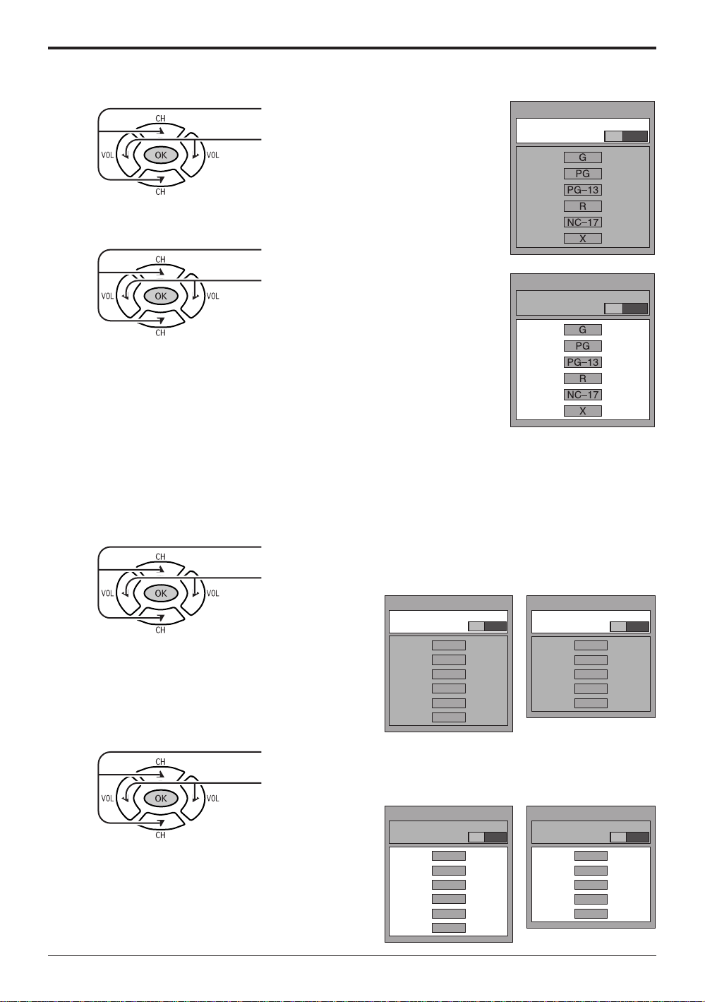
Lock Feature
for U.S.MOVIES to lock
1
Press to select VIEW NR PROGRAMS?.
Press to select NO or YES.
NO :
Cannot view programs with NR signals.
YES: Can view programs with NR signal.
Press to select rating.
2
Press to lock or unlock the rating.
Lock: Red
Unlock : Green
Rating
G : General audience
PG : Parental guidance suggested
PG-13 : Parental guidance needed
under 13 years old
R : Restricted
NC17 : No one under 17 is admitted
X : Pornography
for CANADIAN ENGLISH / CANADIAN FRENCH to lock
U. S. MOVIES
VIEW NR PROGRAMS?
NO YES
U. S. MOVIES
VIEW NR PROGRAMS?
NO YES
1
2
Press to select VIEW E PROGRAMS?.
Press to select NO or YES.
CANADIAN ENGLISH
VIEW E PROGRAMS?
C8
14
18
NO YES
C
+
G
PG
+
+
Press to select rating.
Press to lock or unlock the rating.
Lock: Red
Unlock : Green
CANADIAN ENGLISH
VIEW E PROGRAMS?
C8
14
18
NO YES
C
+
G
PG
+
+
CANADIAN FRENCH
VIEW E PROGRAMS?
CANADIAN FRENCH
VIEW E PROGRAMS?
G
8 ANS
13ANS
16ANS
18ANS
G
8 ANS
13ANS
16ANS
18ANS
NO YES
+
+
+
+
NO YES
+
+
+
+
24
Page 25
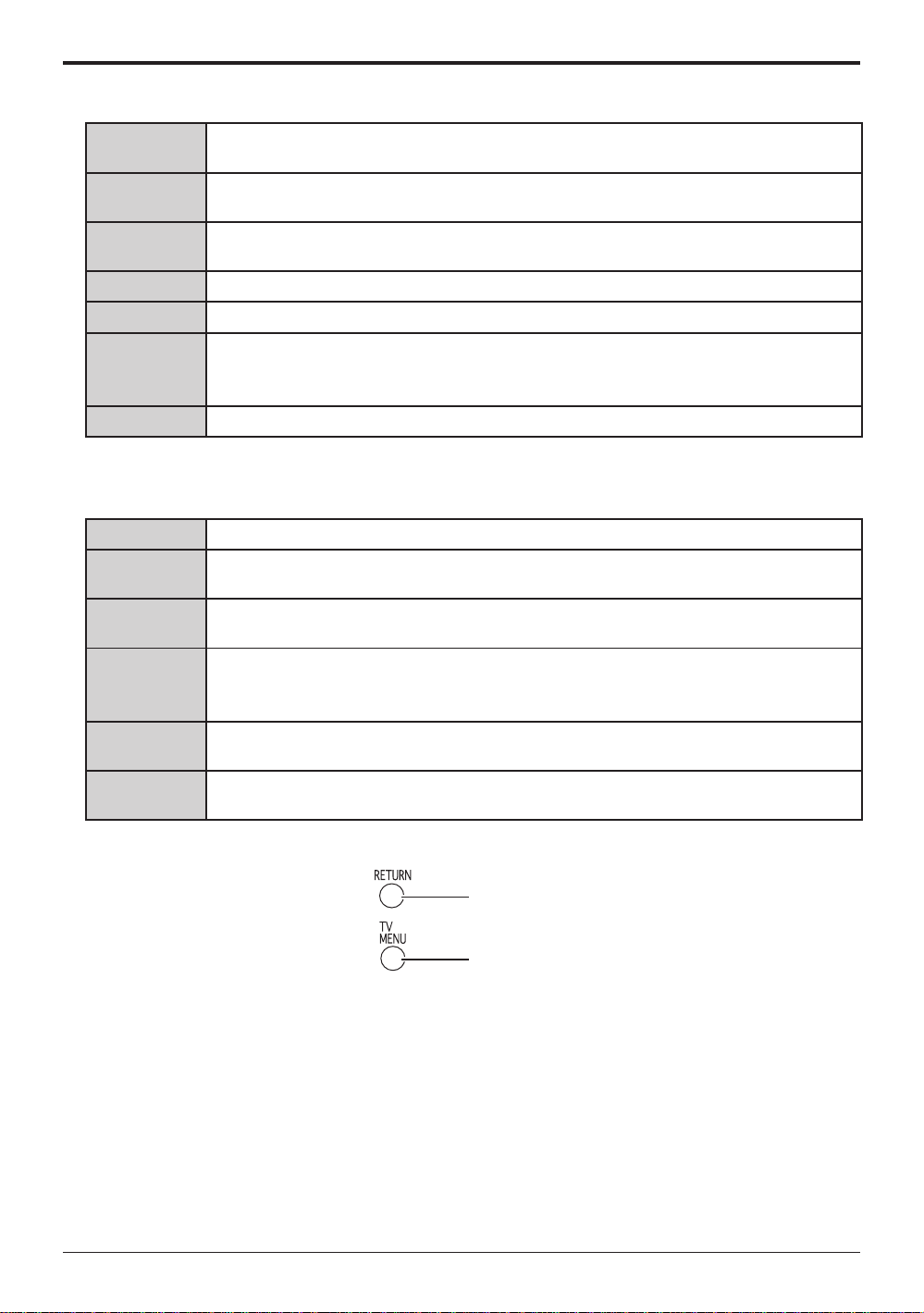
CANADIAN ENGLISH RATINGS CHART
Lock Feature
E
C
C8+
G
PG
14+
18+
CANADIAN FRENCH RATINGS CHART
E
G
8 ANS+
13ANS+
Exempt - Exempt programming includes: news, sports, documentaries and other information
programming, talk shows, music videos, and variety programming.
Programming intended for children under age 8. No offensive language, nudity or sexual
content.
Programming generally considered acceptable for children 8 years and over. No profanity,
nudity or sexual content.
General programming, suitable for all audiences.
Parental Guidance suggested. Some material may not be suitable for children.
Programming contains themes or content which may not be suitable for viewers under
the age of 14. Parents are strongly cautioned to exercise discretion in permitting viewing
by pre-teens and early teens.
General programming, suitable for all audiences.
Exempt - Exempt programming.
General - Programming intended for audience of all ages. Contains no violence, or
the violence content is minimal or is depicted appropriately.
8+ General - Not recommended for young children. Programming intended for a broad
audience but contains light or occasional violence. Adult supervision recommended.
Programming may not be suitable for children under the age of 13 - Contains either a
few violent scenes or one or more sufficiently violent scenes to affect them. Adult
supervisionstrongly suggested.
16ANS+
18ANS+
To return to previous screen :
•
To end adjustments : Press to exit from the MENU screen.
•
Programming may not be suitable for children under the age of 16 - Contains frequent
scenes of violence or intense violence.
18+ ans Programming restricted to adults. Contains constant violence or scenes of
extreme violence.
Press to return.
This returns the set to the normal viewing condition.
25
Page 26
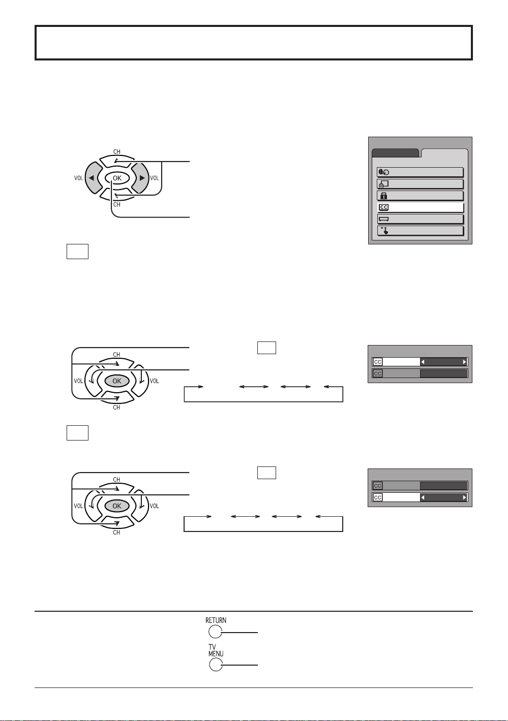
Closed Captions
This unit has a built in decoder that provides a visual depiction of the audio portion
of a television program in the form of written words across the screen (white or
colored letters on a black background). It allows the viewer to read the dialogue of
a television program or other information.
Press the MENU button to display the MENU screen and select SET UP.
1
Press to select CLOSED CAPTION.
Press to display the CLOSED
CAPTION screen.
CC ON MUTE
2
Activates the On-Screen Closed Caption feature, when the MUTE button on the Remote Control is
pressed. To deactivate, press the MUTE button again.
Note:
This feature functions when the Closed Caption Mode is in the “OFF” position.
The program being viewed must be broadcast with Closed Caption.
Press to select
Press to select from the following:
NO(OFF) C1 C2
CC MODE
3
Activates the On-Screen Closed Caption feature. When activated this feature will remain on until
OFF is selected in this menu.
Press to select
Press to select from the following:
ON MUTE.
CC
MODE.
CC
MENU
ADJUST SET UP
LANGUAGE
PROGRAM CH
LOCK
CLOSED CAPTION
INPUT LABEL
OTHER ADJUST
CLOSED CAPTION
ON MUTE
MODE
CLOSED CAPTION
ON MUTE
MODE
NO
OFF
NO
OFF
OFF C1 C2
CAPTION OFF -
•
CAPTION C1 -
•
CAPTION C2 -
•
To return to previous screen :
•
To end adjustments : Press to exit from the MENU screen.
•
Recommended mode when Closed Caption is not being used.
For video related information that can be displayed (up to 4 lines of script strategically
placed on the television screen so that it does not obstruct relevant parts of the picture).
Another mode used for video related information.
Press to return.
This returns the set to the normal viewing condition.
26
Page 27
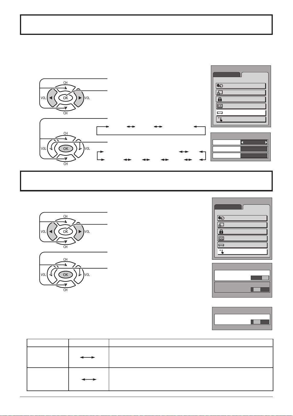
Customizing the VIDEO INPUT labels
Display for each VIDEO INPUT can be changed to match with the connected device
(VCR, DVD Player etc.).
Press the MENU button to display the MENU screen and select SET UP.
1
Press to select INPUT LABEL.
Press to display the INPUT LABEL screen.
2
Press to select the VIDEO INPUT.
VIDEO1 VIDEO2 COMPONENT
Press to change the INPUT LABEL.
VIDEO1 (VIDEO2 or COMPONENT) VCR
[
BLANK] DTV DVD GAME LD
MENU
INPUT LABEL
VIDEO1
VIDEO2
COMPONENT
3D Y/C FILTER / COLOR MATRIX
Press the MENU button to display the MENU screen and select SET UP.
1
Press to select OTHER ADJUST.
MENU
2
Press to display the OTHER ADJUST
screen.
3
Press to select 3D Y/C FILTER
/ COLOR MATRIX.
[ 3D Y/C FILTER ]
Press to select ON or OFF.
[ COLOR MATRIX ]
Press to select SD or HD.
SD : When the input signal is a normal
TV system (NTSC).
HD : When the input signal is a High-
Definition system (ATSC).
OTHER ADJUST
3D Y/C FILTER
COLOR MATRIX
OTHER ADJUST
COLOR MATRIX
ADJUST SET UP
LANGUAGE
PROGRAM CH
LOCK
CLOSED CAPTION
INPUT LABEL
OTHER ADJUST
VIDEO1
VIDEO2
COMPONENT
ADJUST SET UP
LANGUAGE
PROGRAM CH
LOCK
CLOSED CAPTION
INPUT LABEL
OTHER ADJUST
OFF ON
SD HD
[ for
CT-L2000 ]
SD HD
Note: •3D Y/C FILTER is not available for CT-L1400.
Item
3D Y/C FILTER
[ for CT-L2000
COLOR
MATRIX
ON
SD
Mode
OFF
HD
Minimizes noise and cross color in the picture.
Not available for COMPONENT VIDEO.
Displays input signals (480p signals) in a natural color.
Automatically adjusts color parameters for HD (high definition) and
SD (standard definition).
[ for CT-L1400 ]
Explanations
27
Page 28
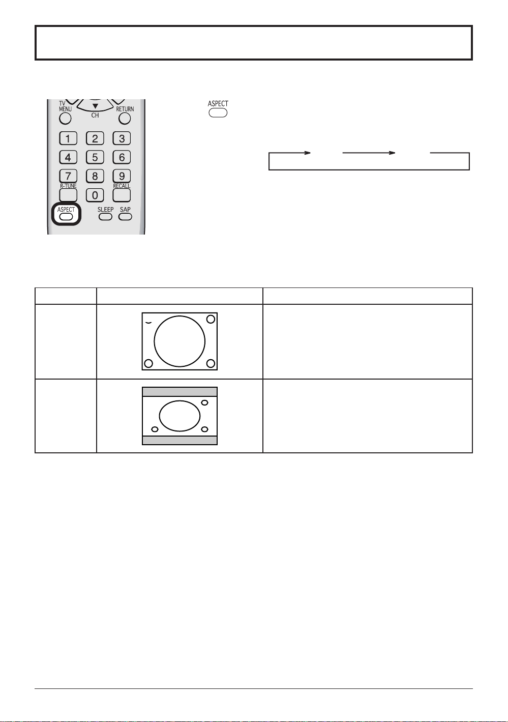
ASPECT Controls
The TV will allow you to enjoy viewing the picture at its maximum size, including wide screen cinema format picture.
ASPECT button
The aspect mode changes each time the ASPECT
button is pressed.
4 : 3
Notes:
In TV mode, the aspect mode is set to 4:3, and ASPECT controls are not available.
•
The ASPECT mode settings are stored for VIDEO1, VIDEO2 and COMPONENT individually.
•
Mode
4 : 3
16 : 9
(not available
in TV mode)
4 : 3
16 : 9
Picture
4:3 mode will display a 4:3 picture at its standard
4:3 size without any stretching.
16:9 mode will display 16:9 aspect ratio picture.
Bars can be seen at the top and bottom of the
image.
Explanation
16 : 9
28
Page 29
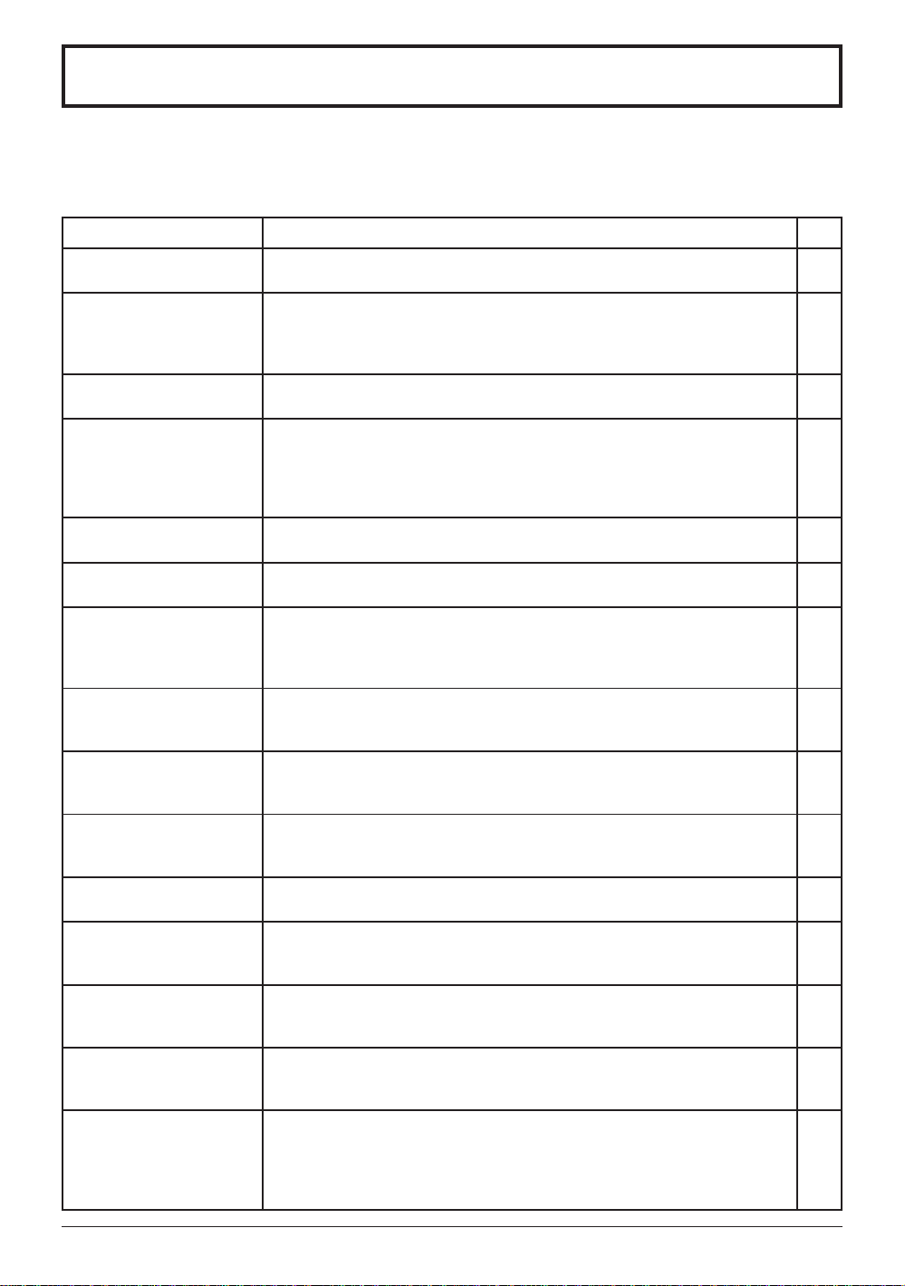
Troubleshooting
Before requesting service for this LCD TV, check the chart below for a possible cause of the problem you are experiencing.
Some simple checks or a minor adjustment on your part may eliminate the problem and restore proper operation.
If you are in doubt about some of the check points, or if the remedies indicated in the chart do not solve the
problem, consult your dealer for instructions.
Symptom
Power supply does not
go on
Remote control cannot
be operated
Image shakes, or image
is unclear
There are spots on the
picture, or the screen
shakes
The image appears
doubled or tripled
A color pattern appears,
or colors disappear
The channel number
disappears from the
screen
When the image is not stable,
the screen turns completely
white for a moment
The screen goes dark
momentarily when the
channel is changed.
The TV makes a hissing
noise occasionally
The screen display
shakes with video input
A black band appears
momentarily when selecting
channels with video
Both edges of the screen,
or columns or window
frames, appear bent
The image from the
connected equipment
does not appear
The main unit is hot to
the touch
Cause and remedy
Is power supply plug unplugged from the outlet?
•
If power will not go on with the remote control, is the power supply of the TV "Off"?
•
Is battery exhausted, or is battery polarity wrong?
•
Is the remote control receiver illuminated with strong light from a fluorescent lamp etc.?
•
Are you using the special-purpose remote control for this equipment?
•
(The unit will not operate with another remote control.)
Is there deterioration, breakage or disconnection of the antenna or antenna wire?
•
Is the antenna wire connected correctly?
•
Is the system affected (by radio wave interference or induced electromagnetic
•
waves) by external sources (automobiles or trains, high-voltage wires, neon,
motors, magnetized steel frame, or iron rain shutters, etc.)?
➠
Turn off the power supply, and try changing the equipment setup location. If
that has no effect, separate magnet-proofing will be required.
Is the antenna direction shifted?
•
Are reflected electromagnetic waves being received from mountains or buildings?
•
Is the equipment being affected by another TV (electromagnetic interference)?
•
➠Changing the TV setup location may lead to improvement.
Has the RECALL button been pressed?
•
➠Press the "RECALL button" again.
If the system is switched to external input and there is no external
signal video, the n
This occurs when the signal driving the liquid crystal is lost, and is not
•
a malfunction.
The screen is darkened for a moment to conceal noise generated when
•
changing channels.
If the screen and audio are not abnormal, this sound is caused by
•
slight expansion and contraction of the cabinet due to changes in room
temperature. It has no effect on performance.
When input is switched to "video input", this may occur if there is no
•
signal at the video/audio input terminal.
This is due to noise generated when changing channels.
•
They may appear bent due to the received channel or some DVD
•
software. This is not a malfunction.
Are plugs securely inserted into each terminal?
•
➠Securely insert plugs all the way.
The main unit radiates heat, so some parts of the console reach a high
•
temperature. This is not a problem for performance or quality .
Set up at a location with good ventilation.
•
Do not cover the ventilation holes of the console with a tablecloth, etc.,
and do not place on top of other equipment (like a video deck).
umber will disappear.
Page
–
13
7
–
–
–
8, 9
–
–
–
15
–
–
–
10, 11
–
–
10,11
–
29
Page 30

30
Page 31
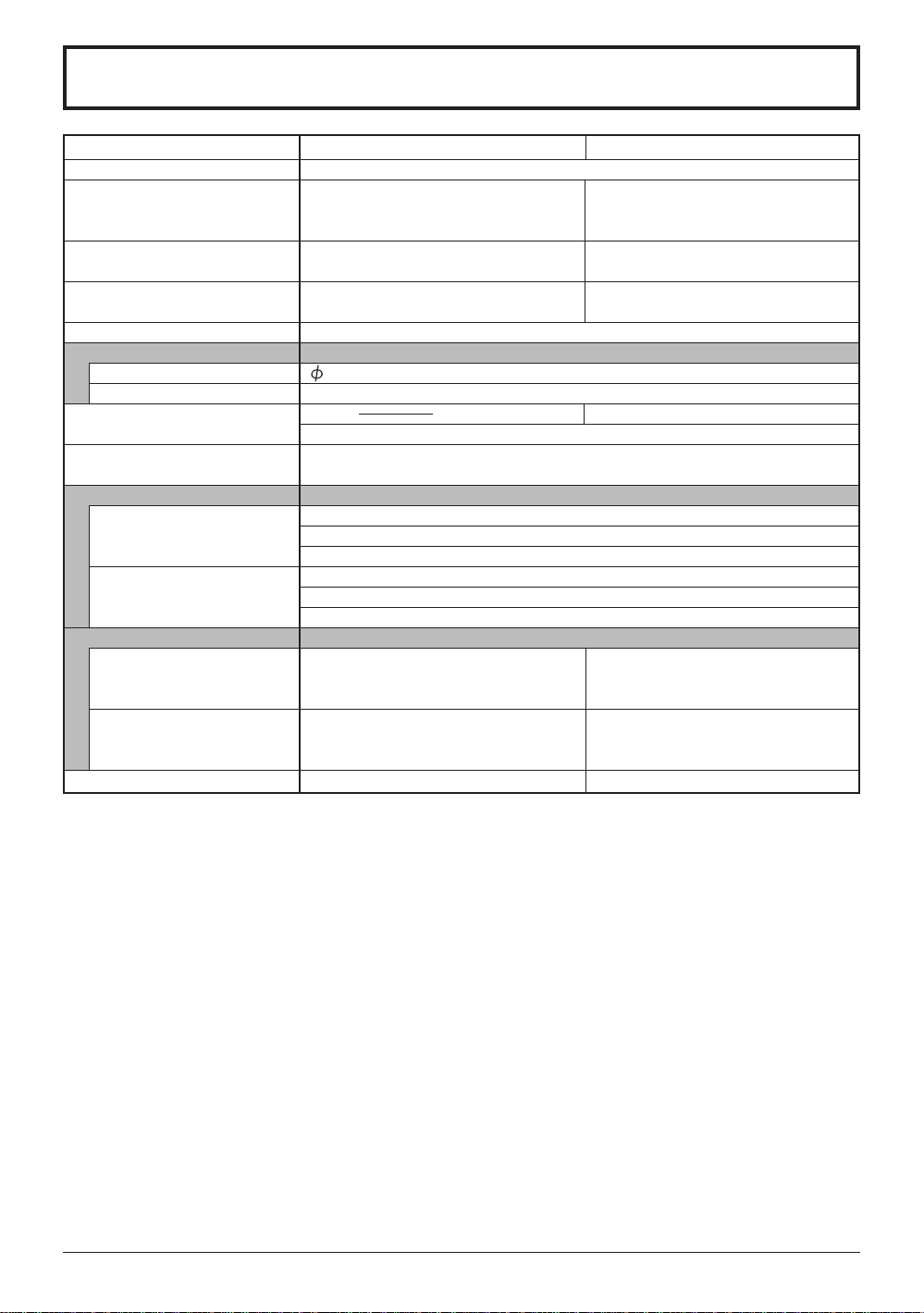
Specifications
Power Source
Power Consumption
LCD
Screen Size
Channel Capability
Sound
Speaker
Headphones
FEATURES
Operating Conditions
Connection Terminals
INPUT
COMPONENT VIDEO
INPUT
××
Dimensions ( W
× H
××
××
× D )
××
Including TV Stand
TV Set Only
Mass (Weight)
CT-L1400
AC 120 V, 60 Hz
Average use : 48W
Stand-by condition : 0.6 W
TV set DC 15 V, 2.8 A max.
14-inch (356 mm),
4 : 3 aspect ratio LCD panel
11.23 ≤ (285.1 mm) (W) ×
8.42 ≤ (213.8 mm) (H)
VHF-12 : UHF-56 : Cable-125
4 cm, 2pcs, 16 Ω
M3 (3.5 mm) Jack × 1
CLOSED CAPTION V-Chip
Temperature : 41 °F - 95 °F (5 °C – 35 °C)
Humidity : 5 % - 90 % RH (non-condensing)
VIDEO (RCA PIN Type × 1) × 2 1.0 Vp-p
S-VIDEO (MINI DIN 4pin × 1) × 2
AUDIO L-R (RCA PIN Type × 2) × 2
Y
PB / P
R
AUDIO L-R (RCA PIN Type × 2)
14.37 ≤ (365 mm) ×
14.34 ≤ (364.2 mm) ×
8.46 ≤ (215 mm)
14.37 ≤ (365 mm) ×
13.01 ≤ (330.5 mm) ×
2.51 ≤ (63.7 mm)
9.701 lb. (4.4 kg) Net
Average use : 67 W
Stand-by condition : 0.8 W
TV set DC 15 V, 3.8 A max.
20-inch (510 mm),
4 : 3 aspect ratio LCD panel
16.06 ≤ (408.0 mm) (W) ×
12.05 ≤ (306.0 mm) (H)
3D Y/C Digital Comb Filter
Y : 1 Vp-p (75 Ω), C : 0.286 Vp-p (75 Ω)
0.5 Vrms
1.0 Vp-p (including synchronization)
±
0.35
Vp-p
0.5 Vrms
19.45 ≤ (494 mm) ×
18.17 ≤ (461.4 mm) ×
10.04 ≤ (255 mm)
19.45 ≤ (494 mm) ×
16.63 ≤ (422.3 mm) ×
3.21 ≤ (81.5 mm)
15.87 lb. (7.2 kg) Net
CT-L2000
(75 Ω)
Note: •Design and Specifications are subject to change without notice. Weight and Dimensions shown are approximate.
31
Page 32

Customer’ Record
The model number and serial number of this product can be found on its rear panel. You should
note this serial number in the space provided below and retain this book, plus your purchase
receipt, as a permanent record of your purchase to aid in identification in the event of theft or
loss, and for Warranty Service purposes.
Model Number Serial Number
Panasonic Broadcast & Television Systems Company
Unit of Matsushita Electric Corporation of America
Executive Office :
One Panasonic Way 4E-7, Secaucus, NJ 07094 (201) 348-7000
EASTERN ZONE : One Panasonic Way 4E-7 Secaucus, NJ 07094 (201) 348-7621
Mid-Atlantic/New England : One Panasonic Way 4E-7 Secaucus, NJ 07094 (201) 348-7621
Southeast Region : 1225 Northbrook Parkway, Ste 1-160 Swanee GA 30024 (770)338-6835
Central Region : 1707 N Randall Road E1-C-1, Elgin, IL 60123 (847)468-5200
WESTERN ZONE : 3330 Cahuenga Blvd W., Los Angeles, CA 90068 (323) 436-3500
Dallas Region : 6226 Abington Way, Houston, TX 77008 (713) 802-2726
No. CA/Northwest Region : 5870 Stone Ridge, #3, Pleasanton, CA (925) 416-5108
Government Marketing Department : 52 West Gude Drive, Rockville, MD 20850 (301) 738-3840
MBS0503S0
Printed in Japan
 Loading...