

Panasonic CT-G2173, CT-20G8, CT-20G8S, CT-20L8, CT-G2133 User Manual
...
Color Television
CT-20G8
CT-20G8S
CT-20L8
CT-G2133
CT-G2133L
CT-G2173
CT-G2173L
TQB2AA0452 30501
PRINTED IN USA
IMPRESO EN EE.UU
IMPRIME_ AUX E_TATS-UNIS
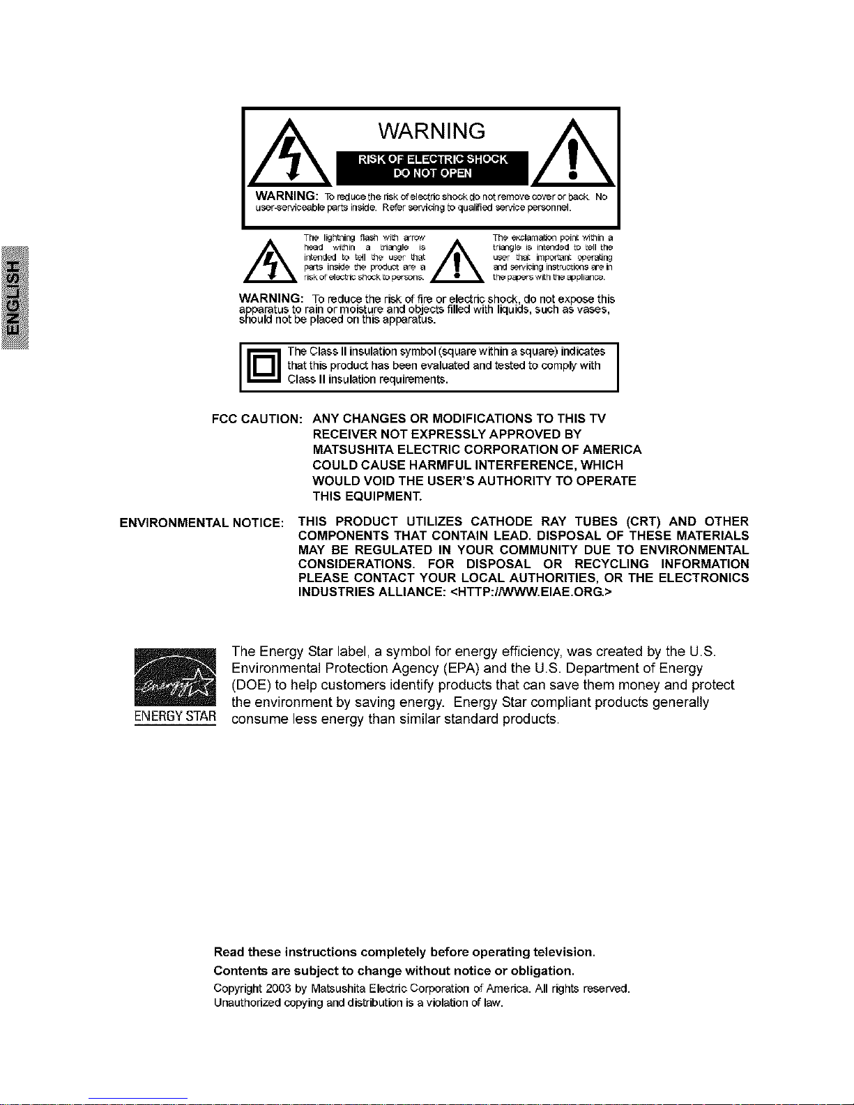
WARNING: Tor_du_ethedskofel_td_sho_kdonotremove¢owrorb_¢k. No
us_r-_ervi_ble p_rt_ inside. Refer _rvi_ing to qualified _rvi_e personnel.
Th_ lightniE_ _]a_q with =rrc_Y
_ h_rl ,_itllin a tri_ngl_ is _
p_, in$irl_ _e prQdu_t _r_ _
ri_k of el_lci_ shOCkto persons.
The _olama_on poi#: wl_qin
triangle is inb_]ded [o _-II the
u_-r that important operating
and _-r_i_inginstruoti_q$ are in
the papers_l_h the appli_noe.
WARNING: Toreduce the risk offire orelec_dcshock do not expose this
apparatus to rain ormoisture and obje_ filled with liquids such asvases
snoud not be 13aced onth s apparatUS.
TheClass IIinsulationsymbol (squarewithin a square) indicates I
thatthis produc_hasbeen evaluated and testedto complywith
I
Class II insulation requirements.
FCC CAUTION: ANY CHANGES OR MODIFICATIONS TO THIS TV
RECEIVER NOT EXPRESSLY APPROVED BY
MATSUSHITA ELECTRIC CORPORATION OF AMERICA
COULD CAUSE HARMFUL INTERFERENCE, WHICH
WOULD VOID THE USER'S AUTHORITY TO OPERATE
THIS EQUIPMENT.
ENVIRONMENTAL NOTICE: THIS PRODUCT UTILIZES CATHODE RAY TUBES (CRT) AND OTHER
COMPONENTS THAT CONTAIN LEAD. DISPOSAL OF THESE MATERIALS
MAY BE REGULATED IN YOUR COMMUNITY DUE TO ENVIRONMENTAL
CONSIDERATIONS. FOR DISPOSAL OR RECYCLING INFORMATION
PLEASE CONTACT YOUR LOCAL AUTHORITIES, OR THE ELECTRONICS
INDUSTRIES ALLIANCE: <HTTP:I/WWW.EIAE.ORG.>
/
ENERGY STAR
The Energy Star label, a symbol for energy efficiency, was created by the U.S.
Environmental Protection Agency (EPA) and the U.S. Department of Energy
(DOE) to help customers identify products that can save them money and protect
the environment by saving energy. Energy Star compliant products generally
consume less energy than similar standard products.
Read these instructions completely before operating television.
Contents are subject to change without notice or obligation.
Copyright 2003 by Matsushita Elec_dcCorporation ofAmedca. All rights reserved.
Unauthorizedcopying anddistribution is aviolation of law.
TABLE OF CONTENTS
Table of Contents
Congratulations ............................................... 2
Customer Record ........................................................ 2
Care and Cleaning ...................................................... 2
Specifications .............................................................. 2
Feature Chart .............................................................. 2
Installation ........................................................ 3
Television Location ..................................................... 3
Optional Cable Connections ....................................... 3
AC Power Supply Cord ............................................... 3
Cable / Antenna Connection ....................................... 3
Important Information Regarding The Use Of Video
Games, Computers, Or Other Fixed Image Displays.. 3
Auto Set Up Menu ............................................ 4
Optional Equipment Connections .................. 5
VCR Connection ......................................................... 5
Front Control Panel ..................................................... 5
Cable Box Connection ................................................ 5
Digital TV - Set-Top Box (DTV-STB) or DVD Player
Connection ................................................................ 5
Remote Control Operation .............................. 6
Battery Installation ...................................................... 6
Icon Menu Navigation ................................... 7
Icon Menu Operation ..................................... 8
Set Up ......................................................................... 8
Picture ......................................................................... 8
Timer ........................................................................... 9
Channels ..................................................................... 9
Audio ........................................................................... 9
Lock ............................................................................ 9
V-Chip Menu Operation ................................ 10
Troubleshooting Chart .................................. 13
Index ............................................................... 14
10
CONGRA TULA TIONS
Congratulations
Your new TV Monitor/Receiver features a solid state
chassis that is designed to give you many years of
enjoyment. It was thoroughly tested and tuned at the
factory for best performance.
Customer Record
The model and serial number of this product are located on
the back of the TV. You should note the model and serial
number in the space provided and retain as a permanent
record of your purchase. This will aid in identification in the
event of theft or loss. Product registration for U.S. customers
is available at: www.prodreg.com/panasonic
Model
Number
Serial
Number
Care and Cleaning
Screen (Turn TV Off)
Use a mild soap solution or window cleaner and a clean
cloth.
DO NOT USE ABRASIVE CLEANERS.
Avoid excessive moisture and wipe dry.
Note: Do not spray any type of cleaning fluid directly on the
screen.
Cabinet and Remote Control
For cabinets and remote control, use a soft cloth
dampened with water or a mild detergent solution.
Avoid excessive moisture and wipe dry.
Do not use benzene, thinner or other petroleum based
products.
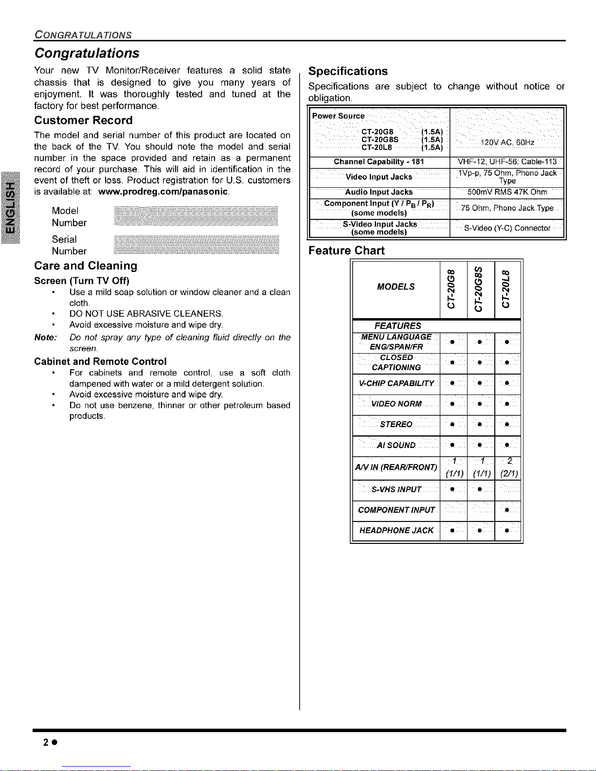
Specifications
Specifications are subject to change without notice or
obligation.
Power Source
CT-20G8 (1.5A)
CT-20G8S (1.5A) 120VAC, 60Hz
CT-20L8 (1.5A)
Channel Capability - 181
Video Input Jacks
Audio Input Jacks
Component Input (Y / P8 / PR)
(some models)
S-Video Input Jacks
(some models)
VHF*12; UHF*56; Cable-113
IVp-p, 75 Ohm, Phono Jack
Type
500mV RMS 47K Ohm
"75 Ohm, Phono Jack Type
S-Video (Y-C) Connector
Feature Chart
(5 (5 "4
MODELS _ _
FEATURES
MENU LANGUAGE ' '
Q Q •
ENG/SPAN/FR
CLOSED ' ' '
CAPTIONING
V-CHIP CAPABILITY • • •
VIDEO NORM •' •
STEREO 'e 'e '•
AISOUND ' s ' s ' s
1 1 2
A/V !N (REAR/FRONT)
(1/1) (1/1) (2/1)
S.VHS INPUT
COMPONENT INPUT •
HEADPHONE JACK • " • " •
20

Installation
Television Location
Follow these recommendations before deciding the
location of your television.
Avoid excessive sunlight or bright lights, including
reflections.
Keep away from excessive heat or moisture. Inadequate
ventilation may cause internal component failure.
Fluorescent lighting may reduce remote control
transmitting range.
Keep away from magnetic equipment, including motors,
fans and external speakers.
WARNING: Use this television receiver only with the
cart, stand, tripod, bracket, or table specified by the
manufacturer, or sold with the apparatus. When a cart
is used, use caution when moving the cart/apparatus
combination to avoid injury from tip-over. In order to
avoid injury to children, never place your television receiver on a
piece of furniture that is capable of being tilted by a child leaning
on it, pulling on it, standing on it, or climbing on it. A falling
television can cause serious injury or even death.
Optional Cable Connections
Shielded audio and video cables should be used between
components. For best results:
Use 75-ohm coaxial shielded cables.
Use appropriate input and output connectors, that match
your component connectors.
Avoid long cables to minimize interference.
AC Power Supply Cord
CAUTION: TO PREVENT ELECTRIC SHOCK,
MATCH WIDE BLADE OF PLUG TO WIDE SLOT
OF AC OUTLET AND FULLY INSERT. DO NOT Polarizedplug
USE A PLUG WITH A RECEPTACLE OR OTHER
OUTLET UNLESS THE BLADE CAN BE FULLY INSERTED TO
PREVENT BLADEEXPOSURE.
PROTECT POWER CORDS FROM BEING WALKED ON, ROLLED
OVER, CRIMPED, BENT, OR PINCHED, PARTICULARLY AT PLUGS,
CONVENIENCE RECEPTACLES,AND THE POINTWHERE THEY EXIT
FROMTHE APPARATUS.
INSTALLA TION
Cable / Antenna Connection
For proper reception, either a cable or antenna connection
is required.
Cable Connection
Connect the cable supplied by your local
cable company.
Note: A cable converter box may be
required for proper reception.
Check with your local cable
company for compatibility
requirements.
Antenna Connection
Note:
Incoming Cable from
Cable Company
75 Ohm VHF/UHF
on back of TV
For proper reception of VHF/ IncomingCablefrom
UHF channels, an external HomeAntenna
antenna is required. For best
reception an outdoor antenna
is recommended.
Cable Made is preset at the
factor_ Antenna users must
change to TV Mode in the Set Up menu under Prog
Chan.
Important Information Regarding The Use Of
Video Games, Computers, Or Other Fixed
Image Displays.
WARNING: The marking or retained image on the
picture tube resulting from viewing fixed image is
not an operating defect and as such is not covered
by Warranty.
This television is designed to display constantly
moving images on the screen. Continuous viewing of
stationary images such as letterbox pictures on
standard screen TVs (with top/bottom bars), non-
expanded standard (4:3) pictures on wide screen TVs
(with side bars shown on each side of an image), stock
market report bars (ticker running at the bottom of the
screen), video game patterns, fixed scoreboards,
bright station loges, on-line (Internet) or repetitive
computer style patterns should be limited.
The extended use of fixed image program material can
cause a permanent picture tube damage, shown as a
"shadow image" viewable on normal programs. This
type of irreversible picture tube deterioration can be
limited by performing the following steps:
Do not displaythe fixed image for extended periods
of time.
Turnthe poweroff when not in use.
30
AUTO SET UP MENU
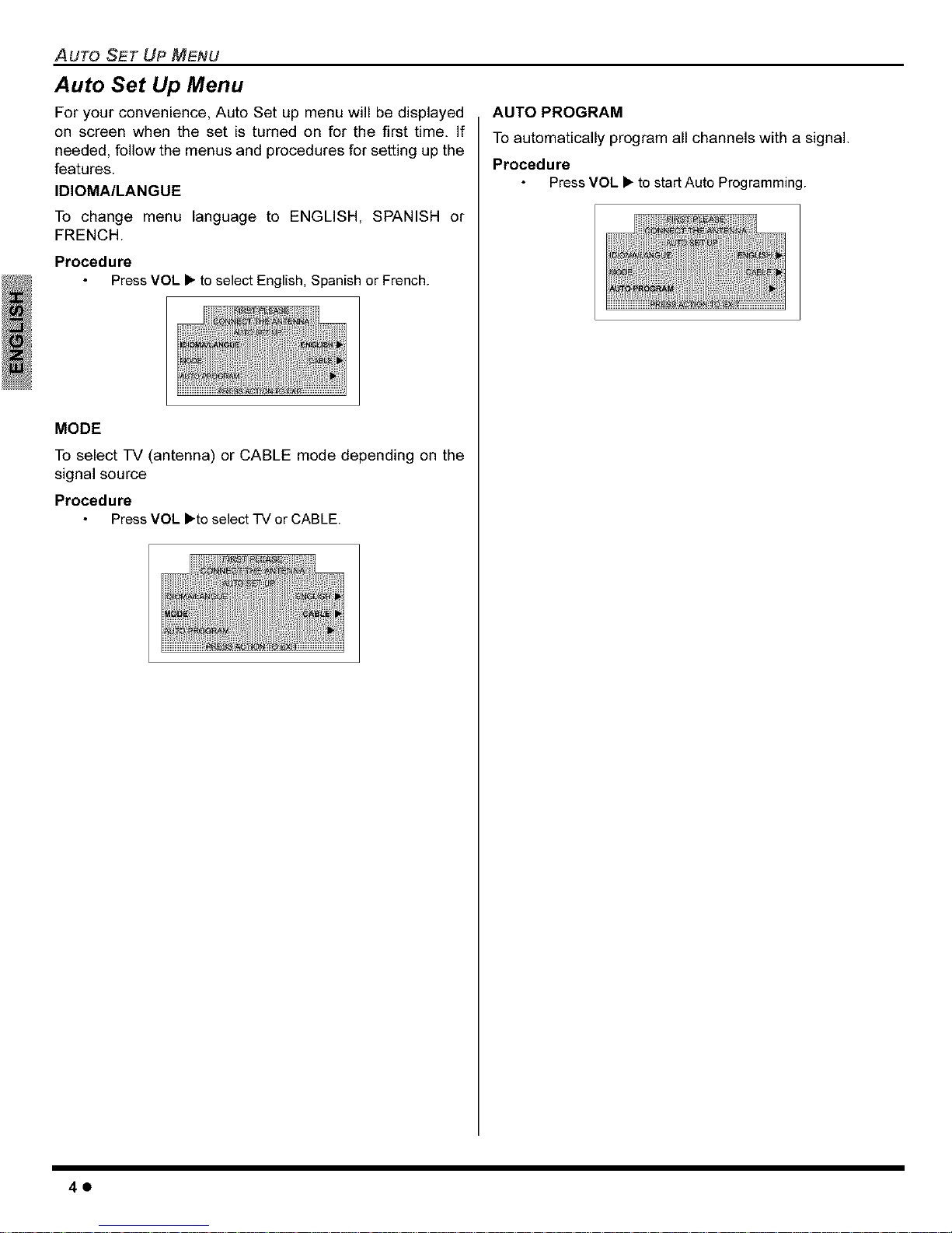
Auto Set Up Menu
For your convenience, Auto Set up menu will be displayed
on screen when the set is turned on for the first time. If
needed, follow the menus and procedures for setting up the
features.
IDIOMA/LANGUE
To change menu language to ENGLISH, SPANISH or
FRENCH.
Procedure
Press VOL • to select English, Spanish or French.
MODE
To select TV (antenna) or CABLE mode depending on the
signal source
Procedure
Press VOL •to select TV or CABLE.
AUTO PROGRAM
To automatically program all channels with a signal.
Procedure
Press VOL • to startAuto Programming.
40
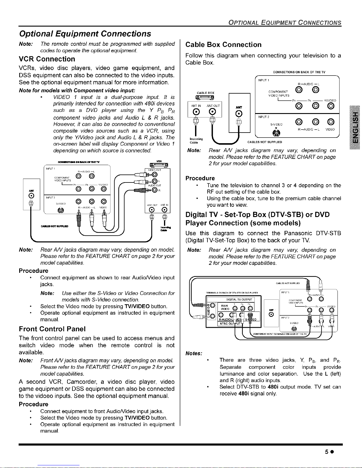
Optional Equipment Connections
Note: The remote control must be programmed with supplied
codes to operate the optional equipment.
VCR Connection
VCRs, video disc players, video game equipment, and
DSS equipment can also be connected to the video inputs.
See the optional equipment manual for more information.
Note for models with Component video input:
VIDEO 1 input is a dual-purpose input. It is
primadly intended for connection with 480i devices
such as a DVD player using the Y PB PR
component video jacks and Audio L & R jacks.
However, it can also be connected to conventional
composite video sources such as a VCR, using
only the Y/Video jack and Audio L & R jacks. The
on-screen label will display Component or Video 1
depending on which source is connected.
_N_ONS ON BACK_ _E _V
INPUTI
R ^LSDIO •
........ © ©
L_pI_ pl_ YNID_O
. © © ©
INPUT 2
...... © © ©
_ Augo • VlDO
_ Nm_JPtqJED _
i
IJ
Note: Rear A/V jacks diagram may vary, depending on model
Please refer to the FEATURE CHART on page 2 for your
model capabilities.
Procedure
Connect equipment as shown to rear Audio/Video input
jacks.
Note: Use either the S-Video or Video Connection for
models with S-Video connection.
Select the Video mode by pressing TVNIDEO button.
Operate optional equipment as instructed in equipment
manual.
Front Control Panel
The front control panel can be used to access menus and
switch video mode when the remote control is not
available.
Note: Front A/V jacks diagram may varyl, depending on model
Please refer to the FEATURE CHART on page 2 for your
model capabilities.
A second VCR, Camcorder, a video disc player, video
game equipment or DSS equipment can also be connected
to the vidoeo inputs. See the optional equipment manual.
Procedure
Connect equipment to front Audio/Video input jacks.
Select the Video mode by pressing TVNIDEO button.
Operate optional equipment as instructed in equipment
manual
OP_ONAL EQUIPMENT OONNEC_ONS
Cable Box Connection
Follow this diagram when connecting your television to a
Cable Box.
r
_i_ I
CONNECTIONS ON BACK OF THE TV
INPUT I
R--AUDIO --L
COMPONENT O O
VIDEO INPUTS
L-- p_ -- p -- y/V_DEC
© © ©
INPUT 2
© © ©
R_AUDIO --L VIDEO
• J
CABLES NOT SUPPLIED
Note:
Rear A/V jacks diagram may vary, depending on
model. Please refer to the FEATURE CHART on page
2 for your model capabilities.
Procedure
Tune the television to channel 3 or 4 depending on the
RF out setting of the cable box.
Using the cable box, tune to the premium cable channel
you want to view.
Digital TV - Set-Top Box (DTV-STB) or DVD
Player Connection (some models)
Use this diagram to connect the Panasonic DTV-STB
(Digital TV-Set-Top Box) to the back of your TV.
Note: Rear A/V jacks diagram may va_ depending on
model. Please refer to the FEATURE CHART on page
2 for your model capabilities.
TErMiNALSORB_CKO_ _W STBOR _W _Y_ / I_FUT
MENT I,_P_JTT_Rat NALS Of_ BA OFTHE_
Notes:
There are three video jacks, Y, PB, and PR-
Separate component color inputs provide
luminance and color separation. Use the L (left)
and R (right) audio inputs.
Select DTV-STB to 480i output mode. TV set can
receive 480i signal only.
50
 Loading...