

Page 1
Page 2
Color Vidio Motiltor/Reoofvor
Operating Instructions
CT- 36VG50
For additional information about Panasonic products, visit our Internet site on the
World Wide Web at:
http://www.panasonic.com
Page 3

Table of Contents
Specifications
Safety Instructions....................................................4
Introduction ...............................................................6
Average Power Consumption ...................................6
Important Information
FCC Statement
FCC Caution
Installation
Television Location
Optional External Equipment Connections
AC Power Supply Cord
Remote Control Battery Installation
TV Antenna/Cable Connections.............................9
Other Video Equipment..........................................9
Care And Cleaning.................................................9
Location of Controls (TV/Monitor)
Quick Reference Control Operation
Location Of Control For The Home Theater Remote
Unit
Basic Remote Control Functions.........................11
Remote Control Quick Reference Functional
Key Chart
Special Functions
Multi Button..........................................................14
Recall Button........................................................14
R-Tune (Rapid Tune) Button ................................14
Optional Equipment Connection and Operation . 15
Stereo Connection (To Audio AMP)
Video/Audio Connection .......................................15
...........................................................
...............................................
......................................................
..........................................................
................................................................
................................................
............
..........................................
.......................
...........................
......................
..................................................................
.........................................................
...................................................
....................
7
7
8
8
8
10
10
11
12
14
15
TV MODE
Trilingual Animated Icons.....................................16
TV Mode Icons
Menu Language Selection
Picture Adjustments
Picture Norm .................................................... 16
Color, Tint, Brightness, Picture and
Sharpness Adjustments
Color Temp .......................................................17
Auto Color .........................................................17
Video NR
Audio Adjustments
Audio Norm
Bass, Treble and Balance ...............................18
Mode - Stereo/SAP/Mono
Speaker ............................................................ 19
Surround
Al Sound ...........................................................19
TV/PC/DTV
Set Up Features ..................................................20
Clock Auto........................................................20
Clock Manual
Set Day .............................................................22
.................................................
...................................
.............................................
................................
..........................................................
...............................................
.....................................................
...............................
.........................................................
.........................................................
..................................................
16
16
16
16
17
18
18
18
19
20
22
3
7
8
8
Auto Power On
Geomagnetic Corr (Correction)
Mode ...............................................................23
Auto Program ..................................................24
Manual Program
Closed Caption On Mute
Closed Caption Mode
Timer Features
Sleep Timer
Program Timer ................................................26
Input Select........................................................ 27
Favorite Channel
Channel Scan
Favorite Channel Select
Channel Caption..................................................28
Preset Caption ................................................28
Manual Caption
Lockout Features.................................................30
Lockout Mode
Unlock ..............................................................31
Control Panel Lock Feature...................................31
Programming the Home Theater Remote
Infrared Remote Codes For Components
VCR Infrared Codes Index
Cable Box and CD Players
Infrared Codes Index
Cassette Players, Receivers, and Amplifiers
Infrared Codes Index.........................................35
Laser Disc, DSS, and DVD
Infrared Codes Index.........................................36
................................................
......................
.............................................
.................................
.....................................
...................................................
.....................................................
................................................
..................................................
..................................
...............................................
..................................................
..............
.......
.....................................
.........................................
22
23
24
25
25
26
26
27
27
28
29
30
32
32
33
34
PC MODE
PC Input Connection (Rear)
PC Input Connection (Front).................................38
TV/PC/DTV ..........................................................39
Trilingual Animated Icons......................................39
PC Mode Icons..................................................39
Picture Adjustments..............................................39
Picture Norm
Color, Tint, Brightness, Picture and
Sharpness Adjustments
Color Temp
Audio Adjustments ...............................................40
Audio Norm
Bass, Treble and Balance.................................40
Speaker
Surround ..........................................................41
Al Sound ........................
Set Up Features
Auto Power On..................................................42
Geomagnetic Corr (Correction)
Input Select ..........................................................42
Display Adj ...........................................................43
Display Adjust Chart
2-
............................................
......................................................
.......................................................
...........................................................
..................................................
..................
.................................
..........
........................................
.............
........
........................
.......................
37
39
39
40
40
41
41
42
42
43
Page 4

Table of Contents (cont’d.)
DTV MODE
Components Video Connection
TV/PC/DTV ..................................................................45
Trilingual Animated Icons..........................................45
DTV Mode Icons..............................................45
Picture Adjustments ..................................................45
Picture Norm....................................................45
Color, Tint, Brightness, Picture and
Sharpness Adjustments................................45
Color Temp
Audio Adjustments ................................................... 46
.....................................................
Audio Norm......................................................46
Bass, Treble and Balance................................46
.........................
Specifications
Power Source:
Channel Capability:
Video Input Jacks (2):
Audio Input Jacks (2):
To Audio Amp Jacks:
S-Video Input Jack (2):
DTV Input Jacks:
Stereo Sound:
Surround Sound:
120V ac, 60Hz
181 channels (See chart)
VHF 2-13, UHF 14-69,
Cable 125 channels
IV p-p, 75 ohm, phono jack type
500mV rms, 47K ohm
0-2.0V rms 4.7K ohm
S-Video (Y-C) Connector
Component Video (Y, Ffe , R )
NTSC with DBX Noise Reduction
Matrix
44
46
Speaker
..........................................................
47
Surround ..........................................................47
Al Sound
Set Up Features
Auto Power On
Aspect Ratio
Color Matrix
Geomagnetic Corr (Correction)
..........................................................
..........................................................
.................................................
....................................................
......................................................
.......................
47
48
48
48
48
48
TROUBLESHOOTING SECTION
Troubleshooting Chart ................................................. 49
Computer Resolution Set Up For Windows 95 .. 50
Computer Resolution Set Up For Windows 3.X . 51
Channel Capability Chart
BAND
VHF
UHF
CABLE (Mid-Band) 15
CABLE (Super Band)
CABLE (Hyper Band) 28
CABLE (Ultra Band) 56
TOTAL CHANNELS 181
CHANNELS
12
56
14
Computer Monitor Specifications
PC and Mac Compatible
Viewable Image Size
Dot Pitch
Multi-scan Rate
Horizontal Frequency Range
Vertical Frequency Range
Max. Data Resolution
Linearity Correction
S-Curve Correction
Dynamic Astigmatism and
Focus Correction
Audio Input-computer
Computer Input
Yes
36.0 inches
Data Grade
Yes
15 kHz to 38 kHz
50 Hz to 120 Hz
800 X 600 @ 60 Hz
Automatic
Yes
Yes
Mini-jack on front panel
2-Front and rear 15-pin connector
Signal Capability Chart
Signal
Format
NTSC
VGA
640 X 480
VGA text
VGA
SVGA
mc2
Specifications are subject to change without notice or obligation.
640 X 480
800 X 600
640 X 480
Horiz. Freq.
15.75 kHz 60
31.5 kHz
31.5 kHz
31.5 kHz
37.9 kHz
35 kHz
Freq.
Vert.
Hz Interlaced
Hz
70
Hz
70
Hz
60
Hz
60
Hz
66.6
-3-
Page 5
Safety Instructions
WARNING
RISK OF ELECTRIC SHOCK
DO NOT OPEN
WARNING: To reduce the risk of electric shock do not remove cover or back. No
user-^ervlceable parts inside. Refer servicing to qualified service personnel.
The exclamation point vwthin
a triangle is intended to tell the
user that important operating
and servicing instructions are
in the papers with the
appliance.
A
The lightning flash with
arrow-head within a triangle
is intended to tell the user
that parts inside the product
are a risk of electric shock to
persons.
A
Note To CATV System Installer; This reminder is provided to direct the CATV system installer’s attention to Article
820-40 of the NEC that provides guidelines for proper grounding and, in particular, specifies that the cable ground shall be
connected to the grounding system of the building, as close to the point of cable entry as practical.
Safety Instructions For Television Receivers
1. Read and apply the operating instructions provided with your television receiver.
2. Read all of the instructions given here and retain them for later use.
3. Unplug this television receiver from the wall outlet before cleaning. Do not use liquid or aerosol cleaners. Use a damp
cloth for cleaning.
4. Do not use attachments not recommended by the television receiver manufacturer as they may cause hazards.
5. Do not use this television receiver near water. For example: Avoid placing it near a bathtub, washbowl, kitchen sink, or
laundry tub, in a wet basement, or near a swimming pool, etc.
6. Do not place this television receiver on an unstable cart, stand or table. The television receiver may fall, causing serious
injury to a child or adult, and serious damage to the appliance. Use only with a cart or stand recommended by the
manufacturer, or sold with the television receiver. Wall or shelf mounting should follow the manufacturer’s instructions,
and should use a mounting kit approved by the manufacturer.
6A. An appliance and cart combination should be moved with care. Quick stops, excessive force, and
uneven surfaces may cause the appliance and cart combination to overturn.
7. Slots and openings in the cabinet and the back or bottom are provided for ventilation, and to insure
reliable operation of the television receiver and to protect it from overheating. These openings must not be blocked or
covered. The openings should never be blocked by placing the television receiver on a bed, sofa, rug or other similar
surface. This television receiver should never be placed near or over a radiator or heat register. This television receiver
should not be placed in a built-in installation such as a bookcase unless proper ventilation is provided.
8. Operate only from the type of power source indicated on the marking label. If you are not sure of the type of power
supplied to your home, consult your television dealer or local power company. For television receivers designed to
operate from battery power, refer to the operating instructions.
9. This television receiver is equipped with a polarized alternating-current line plug (a plug having one blade widerthan the
other). This plug will fit into the power outlet only one way. This is a safety feature. If you are unable to insert the plug
fully into the outlet, try reversing the plug. If
the plug should still fail to fit, contact your
electrician to replace your obsolete outlet. Do
not defeat the safety purpose of the polarized
plug.
10. Do not allow anything to rest on the power
cord. Do not locate this television receiver
where the cord will be damaged by people
walking on it.
11. Follow all warnings and instructions marked
on the television receiver.
12. Do not overload wall outlets and extension
cords as this can result in fire or electric
shock.
13. Never push objects of any kind into this
television receiver through cabinet slots as
they may touch dangerous voltage points or
short out parts that could result in a fire or
electric shock. Neverspill liquid of any kind on
the television receiver.
-4-
Page 6

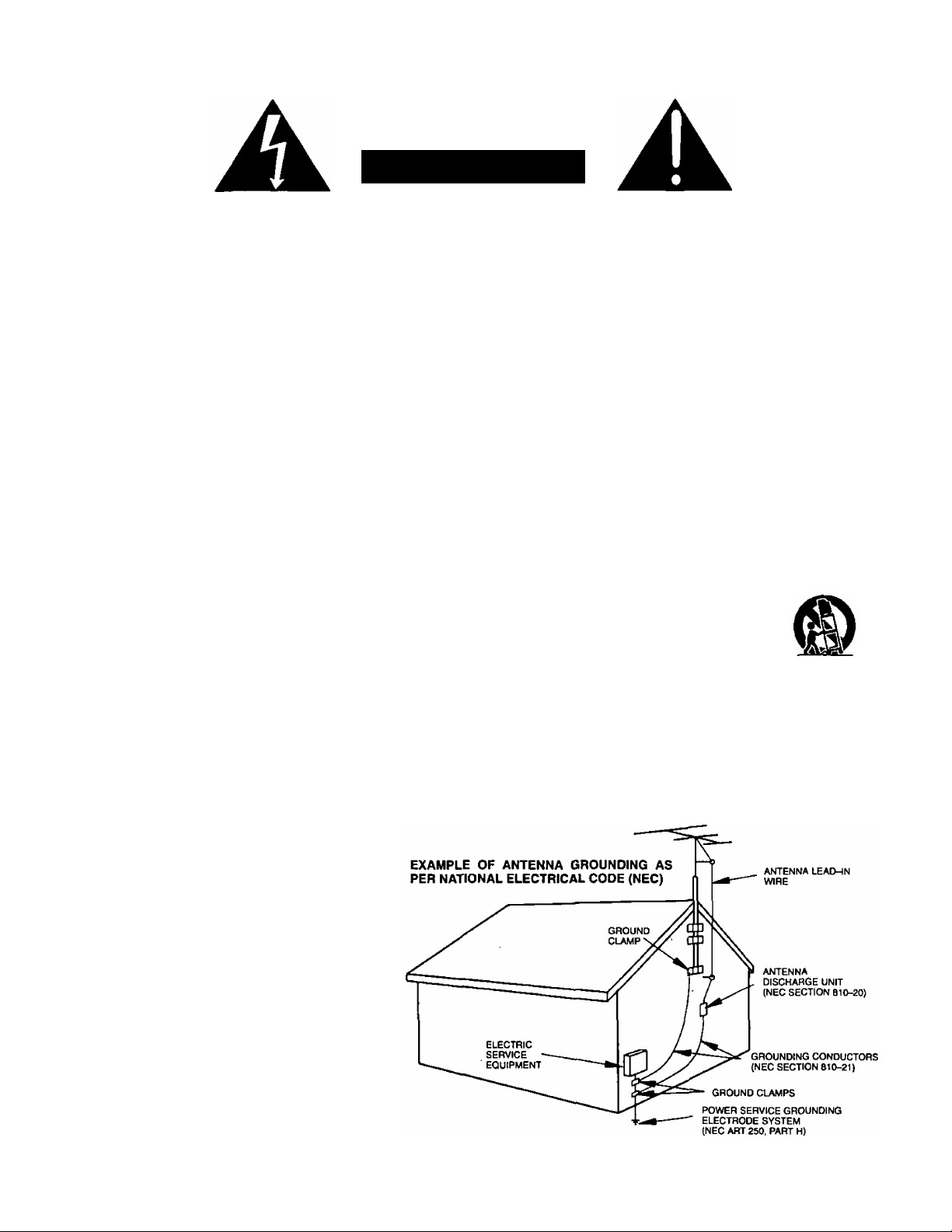
14. If an outside antenna is connected to the television equipment, be sure the antenna system is grounded so as to provide
some protection against voltage surges and built up static charges. In the U.S. Section 810 of the National Electrical
Code and in Canada Part 1 of the Canadian Electrical Code provides information with respect to proper grounding of the
mast and supporting structure, grounding of the lead-in wire to an antenna discharge unit, size of grounding conductors,
location of antenna-discharge unit, connection to grounding electrodes, and requirements for the grounding electrode.
See Figure.
15. For added protection for this television receiver during a lightning storm, or when it is left unattended and unused for long
periods of time, unplug it from the wall outlet and disconnect the antenna. This will prevent damage to the receiver due to
lightning and power-line surges.
16. An outside antenna system should not be located in the vicinity of overhead power lines or other electric light or power
circuits, or where it can fall into such power lines or circuits. When installing an outside antenna system extreme care
should be taken to keep from touching such power lines or circuits as contact with them might be fatal.
17. Unplug this television receiver from the wall outlet, and refer servicing to qualified service personnel under the following
conditions:
When the power cord or plug is damaged or frayed.
a.
If liquid has been spilled into the television receiver.
b.
If the television receiver has been exposed to rain or water.
c.
If the television receiver does not operate normally by following the operating instructions. Adjust only those controls
d.
that are covered by the operating instructions as improper adjustment of othercontrols may result in damage and will
often require extensive work by a qualified technician to restore the television receiver to normal operation.
If the television receiver has been dropped or the cabinet has been damaged.
e.
When the television receiver exhibits a distinct change in performance - this indicates a need for service.
f.
18. Do not attempt to service this television receiver yourself as opening or removing covers may expose you to dangerous
voltage or other hazards. Refer alt servicing to qualified service personnel.
19. When replacement parts are required, be sure the service technician has used replacement parts specified by the
manufacturer that have the same characteristics as the original part. Unauthorized substitutions may result in fire,
electric shock, or other hazards.
20. Upon completion of any service or repairs to this television receiver, ask the service technician to perform routine safety
checks to determine that the television is in safe operating condition.
21. WARNING: To prevent fire or shock hazard, do not expose this appliance to rain or moisture.
22. CAUTION: TO PREVENT ELECTRIC SHOCK DO NOT USE THIS (POLARIZED) PLUG WITH A RECEPTACLE OR
OTHER OUTLET UNLESS THE BLADES CAN BE FULLY INSERTED TO PREVENT BLADE EXPOSURE.
NOTE: This equipment is designed to operate in the U.S. A., Canada and other countries where the broadcasting system and
AC house current is exactly the same as in the U.S.A. and Canada.
Important Information Regarding Use of Video Games, Computers, Teletext or Other Fixed Image Displays.
The extended use of fixed image program material can cause a permanent “shadow image” on the picture tube. This
background image is viewable on normal programs in the form of a stationary fixed image. This type of irreversible picture
tube deterioration can be limited by observing the following steps:
A. Reduce the brightness/contrast setting to a minimum viewing level.
B. Do not display the fixed image for extended periods of time.
C. Turn the power off when not in actual use.
NOTE: The marking or retained image on the picture tube resulting from fixed image use is not an operating defect and as
such is not covered by Warranty. This product is not designed to display fixed image patterns for extended periods of
time.
-5-
Page 7

Congratulations on Your New Purchase
Your new TV/Monitor features an all solid state chassis which is designed to give you many years of enjoyment. It was
thoroughly tested and adjusted at the factory for best performance.
In order for you to take full advantage of your new TV/Monitor, please read and follow the installation and operating
instructions contained herein.
Customer’s Record
The model and serial number of this product may be found on its back cover. You should note the model and serial number
In the space provided and retain this book as a permanent record of your purchase to aid in identification in the event of
theft or loss.
Model Number:
Serial Number:
You may register your new television set on the Internet at:
http ://www. prod reg, com/panason ic
For Customer Assistance; Call the Panasonic Customer Call Center, 2F-3 One
Panasonic Way, Secaucus, NJ 07094 (Headquarters) 800-211-PANA (7262),
Monday-Friday (9 a.m-9 p.m EST), Saturday-Sunday (9 a.m-7 p.m EST),
Average Power Consumption
TV Mode
180W 170W
VGA SVGA
Mode
Mode
175W 1.7W
Standby
Mode
-6-
Page 8
IMPORTANT INFORMATION
FCC STATEMENT:
This equipment was tested and found to comply within the
limits for a Class B digital device, pursuant to Part 15 of
the FCC rules. These limits are designed to provide
reasonable protection against harmful interference in a
residential installation.
This equipment generates, uses and can radiate radio
frequency energy and, if not installed and used in
accordance with the instructions, may cause harmful
interference with radio communications. However, there
is no guarantee that interference will not occur in a
particular installation. If this equipment does cause
harmful interference to radio or television reception, which
can be determined by tuning the equipment on and off, the
user is encouraged to try to correct the interference by one
or more of the following measures:
• Reposition or relocate the receiving antenna.
• Increase the separation between the equipment and
radio/TV receiver.
• Connect the equipment into an outlet on a circuit
different from that to which the radio/TV is connected.
• Consult the dealer or an experienced radio/TV
technician for assistance.
FCC CAUTION:
Pursuant to 47CFR, Part 15.21 of the FCC rules, any
changes or modifications to this monitor not
expressly approved by Matsushita Electric
Corporation of America could cause harmful
interference and would void the user’s authority to
operate this device.
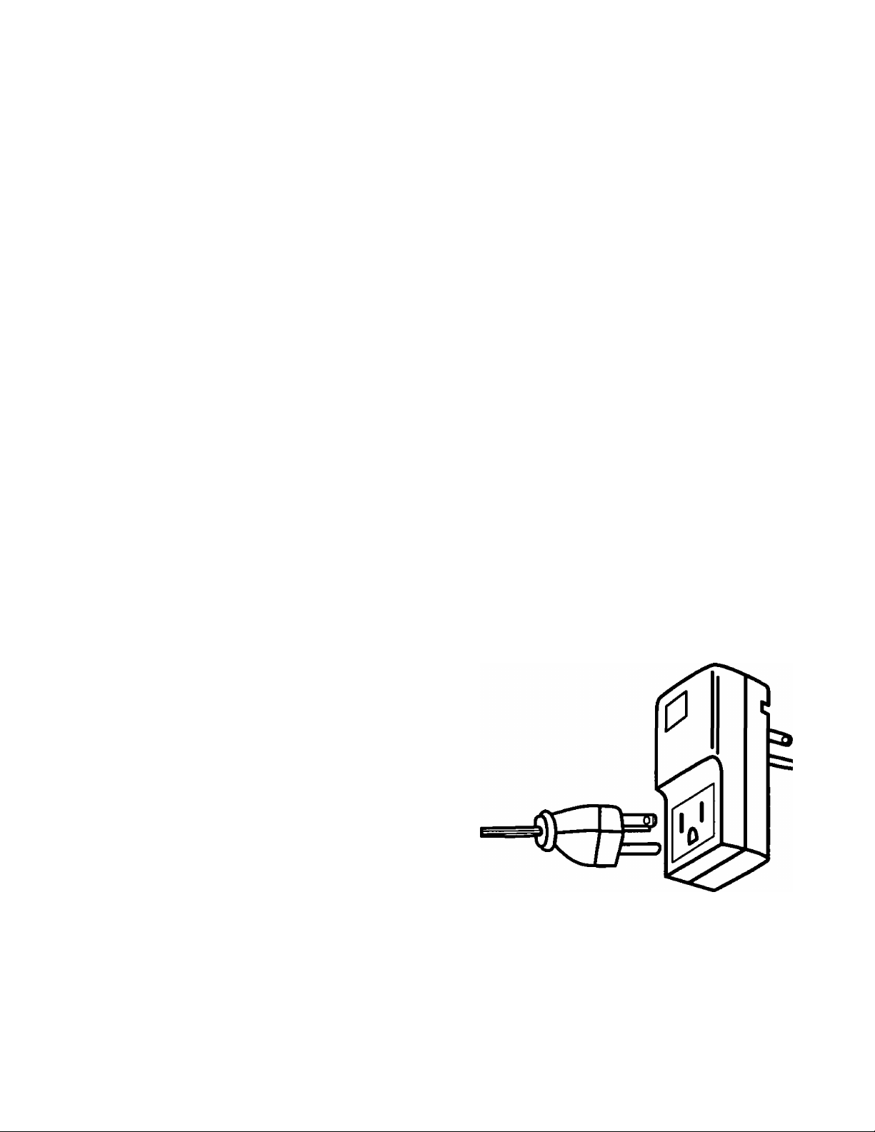
To assure continued compliance, the shielded video
cable with bonded ferrite cores provided must be
used when connecting this TV to a computer device.
(Part # TSX4515-3). The TDK EMI filter, also provided.
Part #ANF-106U, must be used to plug this TV into a
grounding type outlet.
CANADIAN NOTICE;
This class B digital apparatus meets all requirements
of the Canadian Interference-Causing Equipment
Regulations.
AVIS CANADIEN:
Cetappareil numérique de la classe B respecte toutes
les exigences du règlement sur le matériel brouilleur
du Canada.
Important: Changes or modifications not expressly
approved by the party responsible for compliance could
void the user's authority to operate the equipment.
FCC Declaration of Conformity
Responsible party;
Matsushita Electric Corporation of America
One Panasonic Way
Secaucus, NJ 07094
U.S.A.
Telephone number: 1-800-211-7262
9 a.m. to 9 p.m., M-F, EST)
9 a.m. to 7 p.m., Sat-Sun, EST)
This device complies with Part 15 of the FCC rules.
Operation is subject to the following two conditions:
(1) this device may not cause harmful interference,
and (2) this device must accept any interference
received, including interference that may cause
undesired operation.
Three-wire plug with EMI filter
-7-
Page 9
Installation
Video Monitor/Receiver Location
This video monitor/receiver is intended to be used with an optional stand. Consult your dealer for available options.
Locate for comfortable viewing. Avoid placing where sunlight or other bright light (including reflections) will fall on the screen.
Use of some types of fluorescent lighting may reduce remote control transmitter range.
Adequate ventilation is essential to prevent internal component failure. Keep away from areas of excessive heat or moisture.
To insure optimum color purity do not position equipment containing magnets (motors, fans, external speakers, etc.) nearby.
Optional External Equipment Connections
The Video/Audio connections between components can be made with shielded video and audio cables. For best
performance, video cables should be of 75 ohm type coaxial shielded cables. Cables are available from your dealer or
electronic supply house.
Before you purchase any cables, check out the type of output and input connectors your various components require.
Also determine the length of cable you will need.
Power Supply Cord
MAKE SURE PLUG IS INSERTED FULLY INTO THE EMI FILTER. SEE PAGE 7
ILLUSTRATION.
This product is equipped with a three-wire grounding type plug—a plug with two blades and
a third pin which is round. This plug will only fit into a grounding type outlet.
This is a safety feature. If you are unable to insert the plug into the outlet, contact your
electrician to replace your obsolete outlet. DO NOT DEFEAT THE SAFETY PURPOSE OF
THE GROUNDING TYPE PLUG.
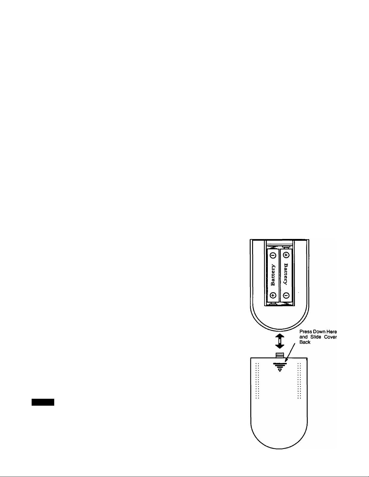
Remote Control Battery Installation
Batteries: Use two “AA” batteries.
1. Remove the battery compartment cover on back of
the remote.
2. Install the batteries in the battery compartment.
(Polarity (+) or (-) must be correct.)
3. Reattach the battery cover.
Helpfui Hints:
For frequent Remote Control users, replace old batteries with
Alkaline batteries for longer life.
Precaution on Battery Use
Incorrect installation can cause battery leakage and corrosion
that will damage the Remote Control.
Observe the Following Precautions:
1. Batteries must be replaced as a pair.
2. Do not combine a used battery with a new one.
3. Do not mix battery types (Example: “Zinc Carbon" with “Alkaline”).
4. Do not attempt to charge, short-circuit, disassemble, heat or burn used
batteries.
5. Battery replacement is necessary when Remote Control reacts
sporadically or stops operating the television.
NOTE:
Whenever you remove the batteries to replace
them, you may need to reset the Remote Control
Infrared Codes. We recommend that you initially
record the codes in the Infrared Remote Codes for
Specific Components section, prior to setting up the
remote.
-8-
Page 10
Installation (cont’d.)
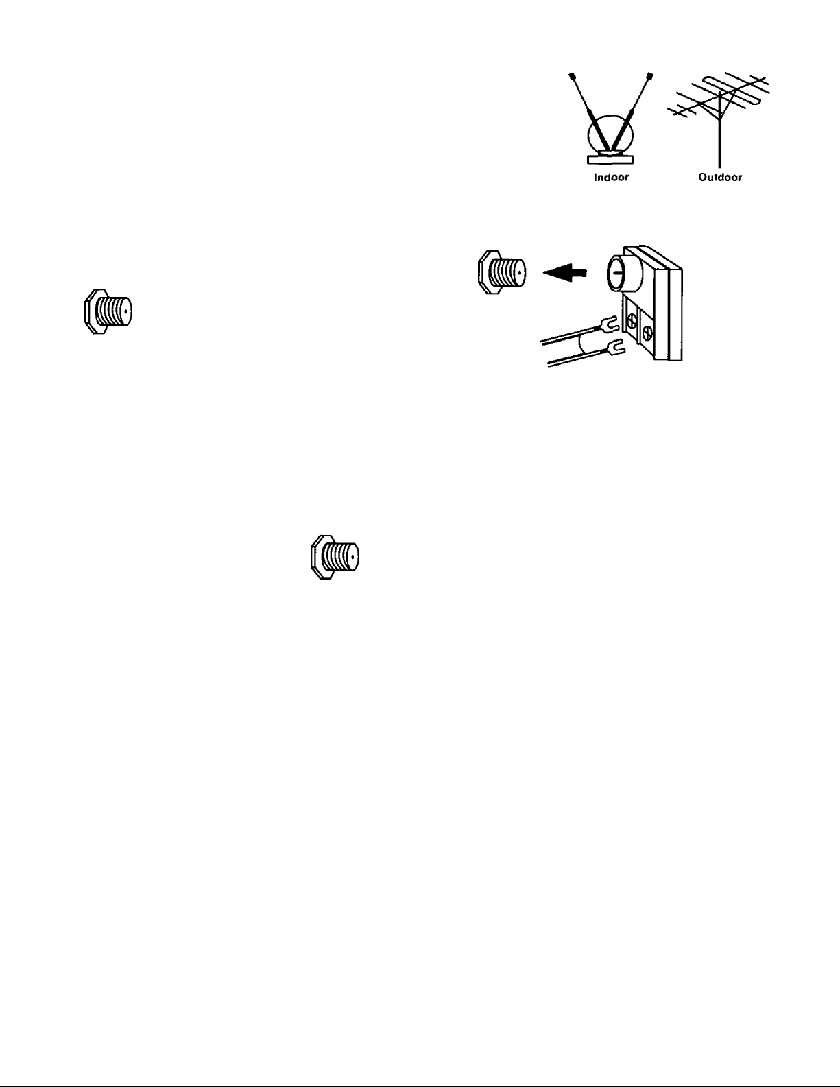
TV Antenna/Cable Connections
Antenna Connection - For proper reception of VHF/UHF channels, an external
antenna is required. For best reception, an outdoor antenna is recommended. In the
SETUP menu, set the MODE to TV. (Refer to Antenna Mode section.)
Incoming Cable from Home Antenna
75 Ohm
VHFAJHF
on Back of Set
Cable Connection - For reception of cable channels, connect the cable supplied by your local cable company. In the
SETUP menu, set the MODE to CABLE. (Refer to Antenna Mode section.)
n
or
VHF/UHF
on Back of Set 300 Ohm
Typical VHF/UHF Antenna
300 to 75 ohm Matching
Transformer (Not Included)
Incoming Cable from Cable Company
75 Ohm
VHF/UHF
on Back of Set
n
NOTE: Certain cable systems offset some channels to reduce interference, or have premium (scrambled) channels. A
cable converter box is required for proper reception. Check with your local Cable company for compatibility
requirements.
Other Video Equipment
VCRs, Video Disc Players, Computers, TV games, and DSS equipment can also be connected to the antenna input
connection.
Care and Cleaning
Picture Tube (Turn television off)
Use a mild soap solution or window cleaner and a clean cloth. DO NOT USE ABRASIVE CLEANERS. Avoid excessive
moisture and wipe dry.
Plastic Cabinet
Wipe the cabinet with a soft cloth dampened with water or a mild detergent solution and wipe dry with a soft clean cloth.
Avoid excessive moisture. Do not use benzene, thinners or other petroleum-based cleaners.
Remote Control Transmitter
Use a soft cloth slightly moistened with a mild detergent and then wipe dry with a soft clean cloth. Avoid excessive
moisture. Do not use benzene, thinners or other petroleum-based cleaners.
-9-
Page 11
Location of Controls (TV/Monitor)
Push here to
open door
O © © © ©
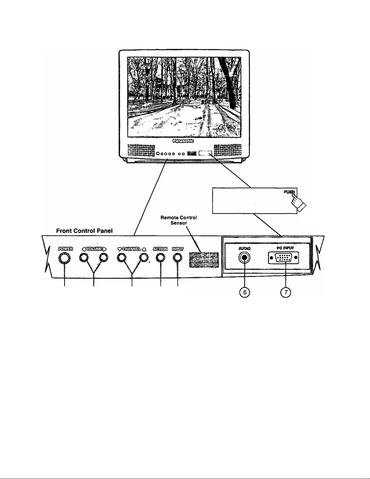
Quick Reference Control Operation
Power Button - Press to turn television ON or OFF.
Volume Buttons - Press to adjust Sound Level, Audio and Video Menus and to select operating features when
menus are displayed.
Channel Buttons - Press to select programmed channels or to highlight desired features when menus are
displayed.
Action Button - Press to display Main Menu and access or exit On Screen feature and Adjustment Menus.
Input Button - TV Mode press to select TV or one of two Video Inputs. PC Mode press to select Front or Rear PC
^ Input.
Audio Input - Use Front PC Audio input jack when connected to a PC sound source Audio output.
PC Input - Connect to a computer having a 15-pin output terminal.
-10-
Page 12
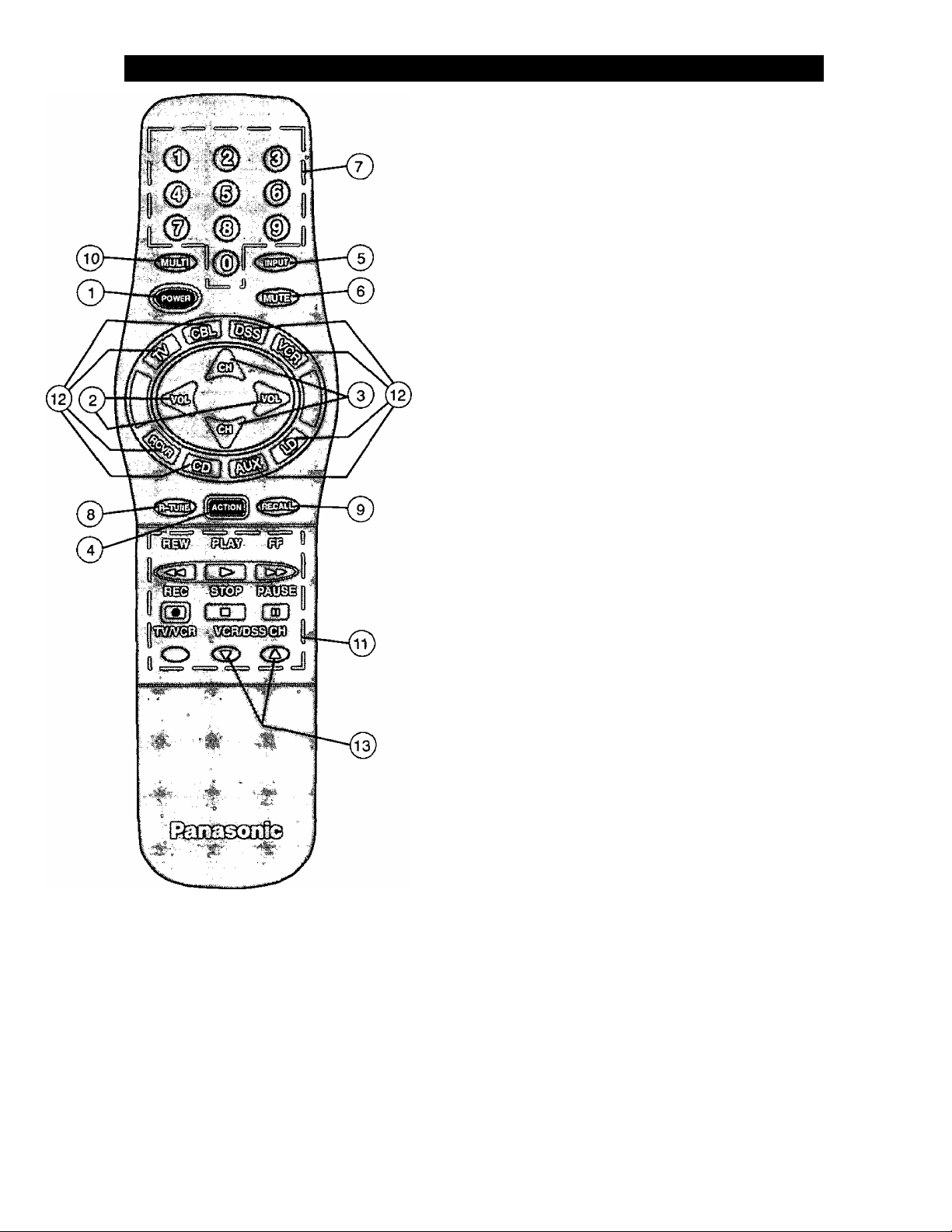
Location of Controls for the Home Theater Remote Unit
Basic Remote Control Functions
Th© loHpwing is ,a basic-^verview of the rernotei control unit foT;
T^^onltor oper^lon. Erieure thé TV button Is seized by
Initially pressing^) .
O
©
©
©
©
©
©
©
©
(10)
©
(12)
0
Power Button - Press to turn the TV ON or OFF.
Volume Buttons - Press to adjust TV sound level. Use
with Channel buttons to navigate in menus.
Channel Buttons - Press to select channels. Use with
Volume buttons to navigate in menus.
Action Button - Press to display Main Menu and access
or exit On-Screen feature and Adjustment Menus.
Input Button - Press to select TV or one of two (2) Video
Inputs. Also used to select Front or Rear PC Input.
Mute Button - Press to mute sound. A second press
returns sound.
Numeric Keypad (0 through 9 Buttons) - Press
desired channel number to access any channel.
R-Tune (Rapid Tune) Button - Switches between two
(2) channels.
Recali Button - Press to display Time, status of Sleep
Timer, Channel, Video Mode, Channel Caption (Station
Identifier), and Audio Mode.
Multi Button - Programmable to operate up to six (6)
Remote Function buttons simultaneously.
VCR Function Buttons - Programmable to operate
many brands of VCR's.
Mode Selection Buttons - Selects the operation mode
for the remote control.
VCR/DSS Channel Buttons - These buttons are used
to select VCR or DSS channels (Up/Down).
Home Theater
Remote Control
TNQ2AE012
Helpful Hints:
If the selected component does not respond to the
remote control, ensure that the proper mode is
selected. First, press the Mode Selection Button
that corresponds to that corhponent. For example,
after first pressing the TV mode button, the remote
will remain in the TV mode for any following
commands. If a different mode button is pressed
while operating the television, the TV mode button
must be pressed again to reset the TV mode
condition.
-11-
Page 13

Remote Control
Quick Reference Functional Key Chart
KEY MODE FUNCTION
© (D (D
0 ® ®
® ® ®
®
TV
VCR, VCR 2
CABLE. DSS
RECEIVER/AMPLIRER
CD PLAYER
Selects Channel
Selects Channel
Selects Channel
® Selects Tuner
® Selects CD Player
® Selects Tape Cassette Player
® VCR1
® VCR 2
Selects Track Number
Qnpu-^
%
%
LD PLAYER
ALL COMPONENTS
TV
ALL COMPONENTS
TV, DSS, VCR, VCR 2 LDP
CABLE
RECEIVER/AMPLIFIER
TV
CABLE
DSS (DIGITAL SATELUTE
SYSTEM)
VCR VCR Mode Selection for Remote Control
RECEIVER/AMPLIFIER
COMPACT DISC
Selects Track Number
Programmable Button That Can Operate Up To Six (6)
Remote Functions At Once
Selects the TV Input Mode
Also Selects Front or Rear PC Input
Turns On and Off Selected Components
Mutes TV Audio
Mutes Audio
Mutes Audio
TV Mode Selection for Remote Control
Cable Mode Selection for Remote Control
DSS Mode Selection for Remote Control
Receiver/Amplifier Mode Selection for Remote Control
CD Mode Selection for Remote Control
A
CASSETTE DECK,
VCR 2, DVD
LASER DISC PLAYER
TV
CABLE
DSS
LDP
CD
RECEIVER/AMPLIFIER
DVD
TV
CABLE
DSS
RECEIVER/AMPLIFIER
VCR, VCR 2
LDP
AUX Mode Selection for Remote Control
Enables User to Operate a Cassette Deck,
Digital Video Disc or Second VCR
LD Mode Selection for Remote Control
Channel Up/Down, Menu Navigation
Channel Up/Down
DSS Guides and Menu Navigation
Skip
FF, REW
Preset or Tuning Frequency
Skip FWD/Skip REW
Volume Up/Down, Menu Navigation
Volume Op/Down
DSS Guides and Menu Navigation
Volume Up/Down
TV Volume Up/Down
TV Volume Up/Down
-12-
Page 14

Remote Control
Quick Reference Functional Key Chart (cont’d.)
KEY
^CAL^
REVt
PLA Y
CSD
MODE FUNCTION
LDP
TV
CABLE
VCR, VCR 2 Switches Between Two (2) Channels
DSS Switches Between Two (2) Channels
RECEIVER/AMPUFIER
CD Selects Next Disc
AUDIO TAPE RECORDER
TV
DSS Acts as Menu Button for DSS
TV
DSS
VCR, VCR 2
LDP
DSS DSS Guide
VCR, VCR 2 Rewind
LDP Rewind
TAPE
CD
DVD
DSS Enter/Select
VCR, VCR 2 Play
LDP Play
TAPE
CD
DVD Play
A/B Repeat
Switches Between Two (2) Channels
Switches Between Two (2) Channels
Switches between AM and FM
Selects Audio Tape Recorder A or B
Activates TV Menus
Displays Channel, Sleep Time,Channel Caption, Time,
and Audio Mode
Displays Current DSS Settings
Displays Current VCR Settings
Displays Current LDP Settings
Rewind
Selects Previous Track
Rewind
Play (in Normal Direction)
Play
FF
REC
STO P
L°J
PAUSE
CZ]
TV/VCR
O
VCR/OS S CH
DSS Exit/Ciear
VCR, VCR 2 Fast Forward
LDP
TAPE
CD
DVD
Fast Forward
Fast Fonward
Selects Next Track
Fast Forward
DSS One Touch Record in DSS Mode
VCR, VCR 2
TAPE
CABLE
DVD
VCR, VCR 2
LDP
TAPE
CD
CABLE
DVD
VCR, VCR 2
LDP
TAPE
CD
CABLE
VCR, VCR 2
DSS
CABLE
VCR, VCR 2
DSS
Record
Record
VCR Record
Stop
Stop
Stop
Stop
Stop
VCR Stop
Pause
Pause
Pause
Pause
Pause
VCR Pause
Selects TVA^CR Mode
Selects TV/DSS Mode
Selects TVA/CR Mode
Channel Up/Down
Channel Up/Down
-13-
Page 15
Special Functions
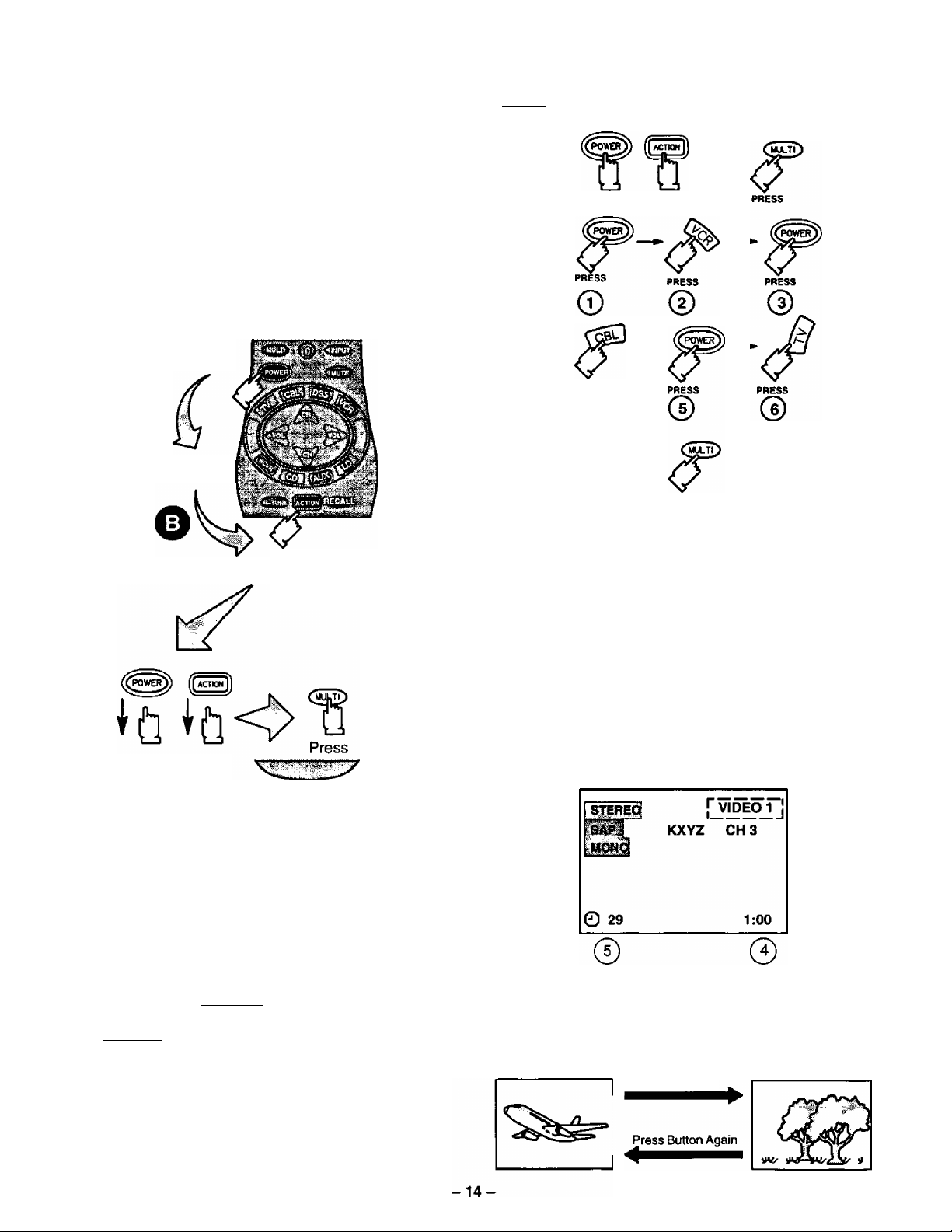
MULTI Button
The MULTI button can be programmed to issue
several commands at the same time.
Example: TV Power/On, VCR Power/On, and
Cable Box Power/On.
Procedure:
1. Enter proper infrared codes for all devices
before programming. See code section.
2. Point your Remote Control transmitter away
from all equipment remote sensors, then:
Press and
keep holding
then ALSO
Press and keep
holding for3
seconds
Release after 3
seconds
The following is a flow chart example of remote
functions that can be programmed into the
0^0 button:
PRESS AT THE SAME TIME
FOR3 SECO NDS
PRESS
©
PRESS TO EXrr
PROGRAMMING MODE
Pressing the button will now activate the
VCR Power/On, Cable Box Power/On, and the
Receiver Power/On at the same time.
RECALL Button
Press the RECALL button to review:
(l) Audio Mode status
@ CH number or Video Input selected
@ Channel Caption (Station Identifier)
(j) Clock time
@ Sleep Timer status
© ©
NOTE: Waiting more than 30 seconds without
pressing another button will exit the
programming mode.
3. Press a maximum of 6 function buttons on the
Remote Control.
Each button you press is equal to one function.
If 6 Remote button functions are entered, all will
register in the CmuTtO button memory when the
sequence is entered. When finished, press the
C>M~Tt>to exit the programming mode.
NOTE: Buttons which continuously perform a
function as long as pressed (Volume Up/Down,
Channel Up/Down, etc.) cannot be programmed:
only those buttons which perform a function
when initially pressed (Power On/Off, Mute,
Direct Channel Entry, etc.) can be
programmed.
©
R-TUNE Button
Pressing the R-TUNE (RAPID TUNE) button toggles to
the previously tuned program.
PROGRAM
CURRENTLY VIEWED
Press Button
PROGRAM
PREVIOUSLY VIEWED
Page 16
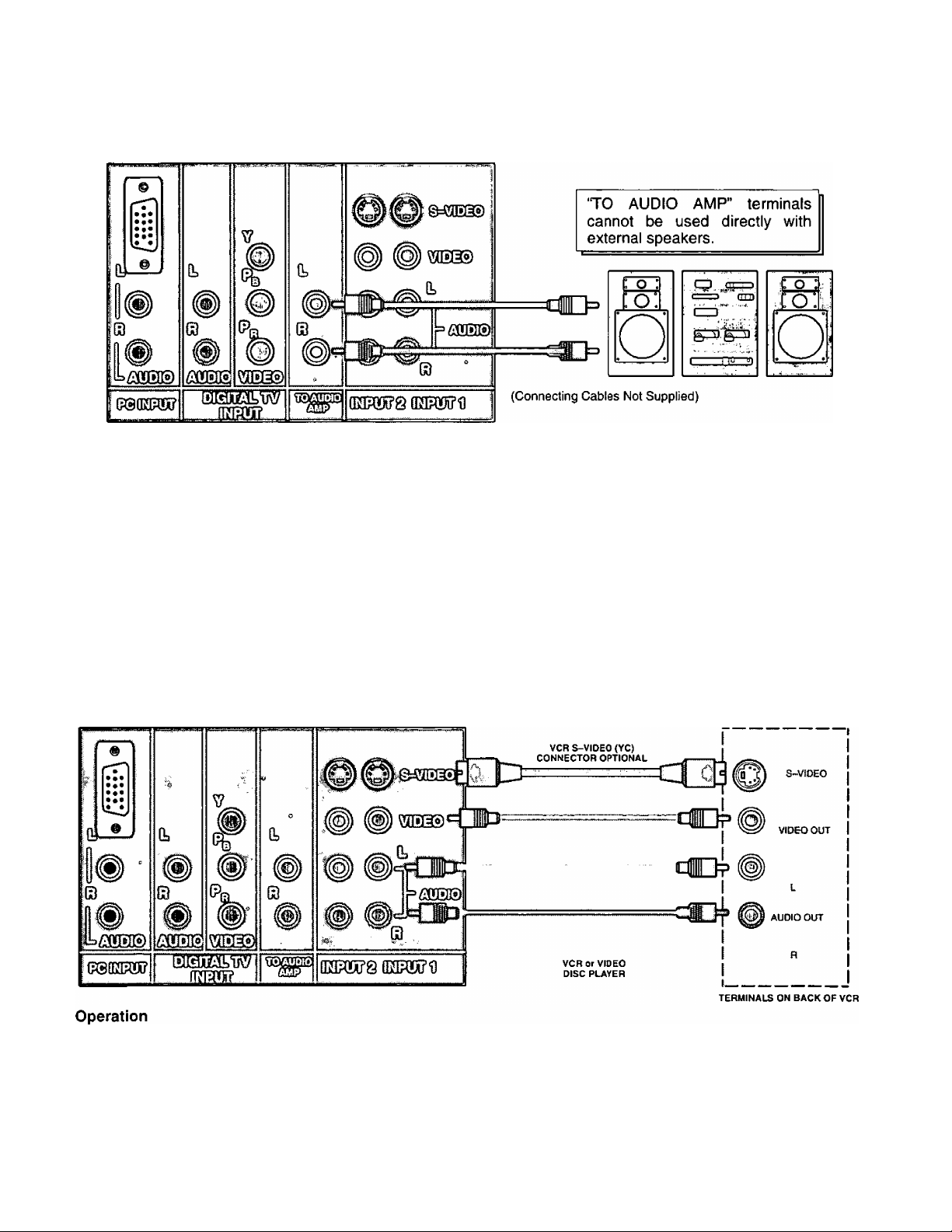
To Audio AMP Connection (Stereo)
Connect to an external audio amp auxiliary input for monitoring sound through a stereo system.
TERMINALS ON BACK OF MONITOR
Adjustment - When an audio amp is connected to ‘TO AUDIO AMP” terminals:
1. Select TV SPEAKERS ‘ON ” Mode. {Refer to the Audio Menu TV Speakers section.)
2. Set volume of audio amp to near minimum.
3. Adjust volume of TV to desired listening level.
4. Adjust volume of audio amp to match the level of TV.
5. Select TV SPEAKERS “OFF&VAO” Mode. (Refer to the Audio Menu TV Speakers section.)
6. Audio bass, treble, balance, volume and mute can now be controlled by the TV Remote Control.
NOTE: When Selecting TV SPEAKERS “OFF&FAO” Mode, the TV sound output is always at a constant level and cannot
be changed (Refer to the Audio Menu TV Speakers section).
AudioA/ideo Input Connection
S-Video connection is optional
and overrides the standard Video
connection when connected.
TERMINALS ON BACK OF MONITOR
T. uonneci optional equipment as snown to iivru i i or ^ terminals, it o-vioeo is to oe useo, connect c>-v
OPTIONAL EQUIPMENT
connector to S-Video terminal 1 or 2 and connect audio cables to L & R Audio INPUT 1 or 2 terminals.
2. Select the desired Video mode by pressing Input or TVA/IDEO button.
3. Operate optional equipment (VCR, DVD or VDP) as instructed in Optional Equipment manual.
NOTE:
® You must select the proper VIDEO Input Mode where the equipment is connected.
• Connection of optional S-VIDEO jack automatically disconnects Video Input 1 or 2 jacks.
-15-
Page 17
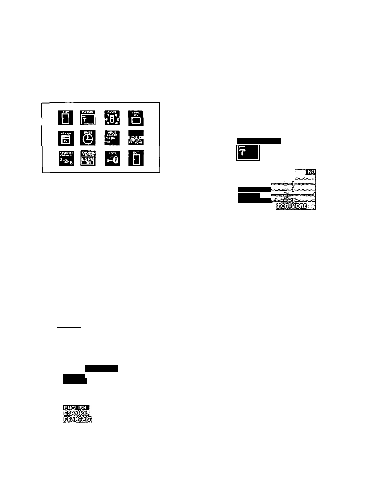
Trilingual Animated Icons
Picture Adjustments
The Icons allows the users to configure the TV
according to their preference. It will also set up the
monitor to operate with external components
connected to the terminal jacks.
TV Mode Icons
NOTE: Only the selected icon (red) will be animated.
¿crióÑTfl Display and Exit Menus
CH BUTTONS
Highlight Desired
A
W
Located On Remote Control
Feature on Menus
VOL BUTTONS
Selects or Adjusts
Features on Menus
Menu Language Selection
The MENU LANGUAGE is factory set to ENGLISH.
Follow the instructions to change it to SPANISH,
FRENCH, and back to ENGLISH (TV, PC, and DTV
mode).
1. Press LLsugiJj.
2. Press ^ or ^ and ^ or ^ to highlight the
Language ENGLISH/ESPANOL/FRANgAIS Icon.
3. Press iLssil] to display the Language select menu.
Picture Norm
Use to reset Color, Tint, Brightness, Picture, and Sharpness
adjustments to the factory preset level for TV Mode only.
1, Presses.
2. Press A or W and ^ or ^ to highlight the Picture
Icon.
3. Press I
4. Press A or ^ to highlight PICTURE NORM.
5. Press or ^ to select “SET to normalize Color,
Tint, Brightness, Picture, and Sharpness.
6. Press ^3 twice to exit menus.
to display the Picture Adjustment menu.
“ÍM?
BRIGHTNESS
pAmim
SHARPNESS
Color, Tint, Brightness, Picture, and Sharpness Adjustments
Helpful Hints:
COLOR - Adjust for desired color intensity.
TINT - Adjust for natural flesh tones.
BRIGHTNESS- Adjust so dark areas of picture slightly
become black for a crisp detail.
PICTURE - Adjust the white areas of the picture as
desired.
SHARPNESS - Adjust for best clarity of outline detail.
ESPAÑOL
FRANÇAIS
4. Press A or ^ to select ENGLISH, ESPAÑOL
FRANÇAIS for the Language Menu.
5. Press twice to exit menus.
1. Press IBJ.
2. Press A or ^and^ or ^ to highlight the Picture
Icon.
3. Press ILesiJJ to display the Picture Adjustment menu.
or
-16-
Page 18

Picture Adjustments (cont’d.)
Color, Tint, Brightness, etc. (cont’d.)
4. Press ^ or V to select the desired Picture
Adjustment {Color, Tint, Brightness, Picture, or
Sharpness).
5. Press or ^ to adjust your selection. (The
Selected Picture Adjustment will be displayed.)
6. Repeat steps 4 and 5 for the remaining Picture
Adjustments.
7. Press (^3 twice to exit menus.
Color Temp
To select one of three (3) options for picture temperature.
Auto Color
To automatically optimize color adjustment to compensate
for signal variations.
1. Press [(¿sstij]
2. Press ^ or W and or ^ to highlight the Picture
Icon.
3. Press I
4. Press ^ or W to highlight AUTO COLOR.
5. Press or ^ to select ON or OFF.
6. Press [fed) twice to exit menus.
to display the Picture Adjustment Menu.
PICTURE;
ifilellifùrHints:
NORMAL-No tint
WARM-Reddish tint
COOL - Bluish tint
1. Press (^).
2. Press ^ or ^and'€ or to highlight the Picture
Icon.
3. Press to display the Picture Adjustment menu.
4. Press ^ or W to highlight COLOR TEMP.
5. Press or ^ to select NORMAL, WARM, or COOL.
6. Press twice to exit menus.
_____
Video NR
This feature increases the horizontal resolution in the
picture.
1. Press [fe^I
2. Pressi or or to highlight the Picture
Icon.
3. Press [feid) to display the Picture Adjustment menu.
4. Press A or ^ to highlight VIDEO NR (Noise
Reduction).
5. Press or ^ to select ON or OFF.
6. Press twice to exit menus'.
-17-
Page 19

Audio Adjustments
meimuimints: ■
"
Setting TV mode Audio Adjustments will also
change PC Mode and DTV mode Audio
Adjustments.
Audio Norm
This feature is used to reset Bass, Treble and Balance
back to a factory preset level.
1. Press .
_ _ ________
"¿i:—ana or lo nigniignt me Auaio
Icon.
3. Press
_____
, _____—
______
______—-.......
to display the Audio Adjustment Menu.
*;:.*ypio . .^PUCSOI
fì^iì
AUDIONORM
AUDIO ; lAUPlO:
A SB ^
„
4. Press ^ or ^ to highlight BASS, TREBLE or
BALANCE.
5. Press or to adjust for desired audio response.
6. Repeat steps 4 and 5 for remaining audio functions.
7. Press the ^3 twice to exit menus.
Mode - Stereo/SAP/Mono
When Audio is broadcast in Stereo or SAP an ON
Screen display will appear on initial ‘Turn On” and
“Channel Change”. The available choices will be
indicated in red.
4. Press A or ^ to highlight AUDIO NORM.
5. Press ^ or ^ to select “YES” to Normalize Bass,
Treble and Balance.
6. Press ^3) twice to exit Menus.
Bass, Treble & Balance
imipfui Hints:
BASS - To increase or decrease the Bass response.
TREBLE - To increase or decrease the Treble
response.
BALANCE - To emphasize the Right and Left
Speaker's volume.
1. Press (t**™*Ji.
2. Pressi or Wand'€ or ^ to highlight the Audio
Icon.
3. Press to display the Audio Adjustment Menu.
iHelpfulsHintSR
STEREO - Two channel audio reception.
SAP - Second Audio Programming (such as bilingual
audio, weather reports, etc.).
MONO - Use when stereo signal is weak.
1. Press [SJ.
2. Press ^ or ^ and or ^ to highlight the Audio
Icon.
3. Press the^3 to display the Audio Adjustment Menu.
4. Press ^ or^ to highlight MODE.
5. Press or ^ to select STEREO, SAP (Second
Audio Programming) or MONO. The selected mode
will be highlighted.
6. Press twice to exit menus.
-18-
Page 20

Audio Adjustments (cont’d.)
Speaker
This feature is used to turn the internal speakers “ON” or
"OFP. It is used when the TV is connected to an external
audio amplifier. (Refer to “To Audio Amp” connection
section for further information.)
1. Press IS).
2. Press^^ or^^ and^^or^^ to select the Audio Icon.
3. Press ^3 to display the Audio Adjustment Menu.
4. Press ^ or^ to highlight SPEAKER.
5. Press ^ or ^ to select ON, OFF&VAO or
OFF&FAO.
• ON - TV speakers operate normally.
• OFF&VAO (Variable Audio Output) - TV speakers off,
the sound output varies according to the TV volume,
use the TV remote to control the volume, muting,
bass, treble and balance of the external stereo
system.
• OFF&FAO (Fixed Audio Output) - TV speakers off,
sound output is fixed.
6. Press ^3 twice to exit menus.
Surround
Use the Surround Feature to enhance audio response
when listening to Stereo broadcasts.
1. Press .
2. Press ^ or ^ and or ^ to highlight the Audio
Icon.
3. Press to display the Audio Adjustment Menu.
4. Press A or ^ to highlight SURROUND.
5. Press or ^ to select SURROUND ON or OFF.
6. Press (^3 twice to exit menus.
Al Sound
This feature is used to maintain constant sound level when
switching between,programs with different sound levels.
For example, when the broadcast program switches to a
commercial, the commercial sound level- will be
maintained close to the level of the broadcast program.
1. Press .
2. Press A or W and or ^ to highlight the Audio
Icon.
3. Presses to display the the Audio Adjustment Menu.
AUDIO
4. Press A or W to highlight Al SOUND.
5. Press or ^ to select Al SOUND ON or OFF.
6. Press ^3 twice to exit menus.
-19-
Page 21

TV/PC/DTV
Set Up Features
TV - Television mode
PC - Computer mode
DTV - Digital television mode
1. Press ^3).
2. Press ^ or ^ and or ^ to select the
TV/PC/DTV Icon.
\—'3:—Press display the TV/PC/DTV mode menu.
4. Press or ^ to highlight TV, PC (Front or Rear), or
DTV.
NOTE: Press Input button while in PC mode to select PC
Front or Rear.
Clock Auto (TV Mode)
This feature automatically adjusts the TV clock to the
correct time whenever the TV is tuned to a PBS (Public
Broadcasting Service) station for 10 minutes or until the
correct time and day are displayed (Refer to your local TV
guide for PBS channel number).
NOTE: A plus or minus one-hour offset can be
programmed to adjust the clock when there is a
time zone difference betwaanlhe-RBS-TV-siaiicriand the viewer.
1. Presses.
2. Press ^ or ^ and or ^ to highlight the Set Up
Icon.
3. Press ^3 to display the Set Up menu.
NOTE: This menu is not available when AUTO
POWER ON Is set
5. Press '
twice to exit menus.
4. Pressi or W to highlight CLOCK.
5. Press or ^ to select AUTO ( if necessary).
6. Press W to highlight AUTO TIME SET.
7. Press or ^ to display the AUTO TIME SET Menu.
8. Press A to highlight PBS CHANNEL.'
-20-
Page 22

Set Up Features (cont’d.)
Clock Auto (cont’d)
9. Tune TV or Cable Box to PBS channel, using the
Remote Control Keypad to enter PBS channel
number.
10. Press ^ to highlight TIME ZONE ADJUST.
WAITING FOR CORRECT TIME AND DAY
11. Press ^ for minus one-hour offset or ^ for plus
one-hour offset (if necessary).
2. Pressi to highlight ACTIVATE.
13. Press or ^ to display the AUTO TIME SET
ACTIVATE Menu.
COMPLETED READ MENU
INCOMPLETE READ MENU
14. Press (^3 four times to exit menus.
13. Press or ^ to display the AUTO TIME SET
ACTIVATE menu.
-21 -
Page 23

Set Up Features (cont’d.)
Clock Manual
Clock (when set) will display On Screen at initial turn on,
after a channel change and when pressing It must
be set in order to operate the dual Timer feature.
1. ' Press ^3).
2. Press^ or^ and or ^ to highlight the Set Up
Icon.
3. Press I to display the Set Up menu.
JJOTE:-This-iTis.nu-!£~net-cvai!ab!e-vvheri-AuTG
POWER ON is set.
:^serup^ mwrmj
CLOCK
4. Press A or ^ to highlight CLOCK .
MANUAL
Set Day
The day of the week must be set in order to operate the
Dual Timer feature.
1. Press^3.
2. Press ^ or ^ and *^or^ to highlight the Set Up
Icon.
3. Presses to display the Set Up menu.
3a BB
.
...........
_
ME^^HiflORpORi
4. Press A or W to highlight SET DAY.
5. Press or ^ to select proper day of the week.
6. Presses twice to exit Menus.
_
_ _
I
5. Press or ^ to select MANUAL.
6. Press A or^ to highlight SET TIME.
7. Press or ^ to Set Hours (set AM/PM
accordingly).
8. Press ^ to highlight minutes position.
9. Press or ^ to set minutes.
10. Press' twice to exit menus.
Auto Power On
Automatically turns the television on when a VCR, Cable
Box, etc., are powered. The monitor needs to be plugged
into the switched outlet of the device. Setting the Auto
Power On feature will cancel the time and timer control
settings. The Main Menu Icon for the TIMER CONTROL
will be replaced with an EXIT Icon.
1. Press .
2. Press A or ^ and or ^ to highlight the Set Up
Icon.
3. Press I
to display the Set Up menu.
....
,
S
1
4. Press A or ^ to highlight AUTO POWER ON.
5. Press or ^ to select SET.
6. Press ^3 twice to exit menus.
-22-
Page 24

Set Up Features (cont’d.)
Geomagnetic Corr (Correction)
This monitor incorporates a speciai adjustment feature for
the convenience of the customer. This adjustment is preset
at the factory. However, adjustment may be required when
the monitor is moved (due to the infiuence of earth’s
magnetic fieid) which may cause the picture to titt stightiy. If
necessary, follow these procedures to adjust the tilt.
1. Press
2. Press ^^or^^ and*^or^ to highlight the Set Up
3.
Press A or W to highlight GEOMAGNETIC CORR.
to display the Set Up menu.
Mode
IMPORTANT NOTE: The proper input mode must be
selected for the type of signal at the antenna input.
• TV is used when the television is not connected to a
Cable TV System, for example, when using a VHF/UHF
antenna (Channels 02-69).
• CABLE is used when the television is connected to a
Cable TV System and when not using a Cable Box
(Channels 01-125).
NOTE: Some Cable TV Systems encode (scramble)
program materia) on specific channels. A cable
company supplied decoder is required to
reproduce an acceptable picture. Certain Cable
TV Systems offset some channels to reduce
interference. It will be necessary to use the cable
company supplied converter to receive these
specific channels.
1. Press ^i) ■
2. Press A or ^ and ^ or ^ to highlight the Set Up
Icon.
3. Press to display the Set Up menu.
Press ^ or^ to display the Geomagnetic Correction
adjustment menu.
Press‘d or ^ to adjust the picture tilt until left and
6.
right side of tilt adjustment bar is parallel to the bottom
of picture frame (if necessary).
NOTE: Discoloration may be visible in picture comers
. if tilt bar is not parallel to the bottom of picture
' frame.
4. Press A or W to highlight MODE.
5. Press or ^ to select TV or CABLE.
6. Press twice to exit menus.
-23-
Page 25

Set Up Features (cont’d.)
Auto Program
The Auto Programming feature allows you to place
channels with a video signal into Channel Scan Memory.
When you press ^ or only those channels with a
video signal will accessed. TV or Cable Tuning mode
must be set properly for your system.
1.
2. Press ^ or Wand‘s or ^ to highlight the Set Up
Icon.
3. Press to display the Set Up menu.
Manual Program
This feature allows you to select which channels are
placed into Channel Scan Memory so when you
press ^ or ^ only those channels you desire will be
accessed.
1. Press the .
2. Press ^ or W and ^ or ^ to highlight the Set Up
Icon.
-3- Press fl^^ltQ.djspiay-t.hcSGt-iJprngnu.-----------------------------
SETUP PETiUm
rWIANUAL PROGRAM
ONIM
MODE
4. Press A or ^ to highlight MANUAL PROGRAM.
5. Press ^ or ^ to display Manual. Programming
Menu.
-
4. Press ^ or W to highlight AUTO PROGRAM.
5. Press ^ or ^ to start Auto Programming Scan.
, Channels will automatically advance until all channels
have been scanned.
• Channel numbers with video signal present will turn
blue which indicates stored in Channel Scan Memory.
6. Press twice to exit menus.
NOTE: Some channels with very weak signals may be
locked into memory. These must be deleted
manually using the Manual Program feature.
-24-
6.
Use the Remote Control Keypad numbers “0 through
9” or A or W to select channels. .
7.
Press ^ to add channel(s) to memory (blue). Press
the to delete channel(s) from memory (yellow).
Repeat Steps 6 and 7 to continue adding or deleting
8.
channels.
9. Press I
twice to exit menus.
Page 26

Set Up Features (cont’d.)
CCl On Mute
Activates the On Screen Closed Caption feature when the
on the Remote Control is pressed. To deactivate
press again.
NOTE: This feature only functions when the Close
Caption Mode is in the “OFP position. The
program being viewed must be broadcast with
Closed Caption. (Refer to your local TV guide.)
1. Press Ctej).
2. Press ^ or ^and“^ or ^ to'highlight the Set Up
Icon.
3. Press ^3 to display the Set Up menu.
CC Mode
This television contains a built in decoder that is capable of
providing a visual depiction of the audio portion. The
program viewed must include Closed Captioning (CC) for
the television to display it. CC is displayed in the form of text
across the screen (white or colored letters on a black
background). It allows the viewer to read the dialogue of a
television program or other information.
1. Press (^3 .
2. Press A or W and or ^ to highlight the Set Up
Icon.
___
3. Press(^3 to display the Set Up menu.
4. Press A orto highlight CC ON MUTE.
5. Press ^ or ^ to select NO, Cl, C2, C3 or C4.
Recommended Set Up for Closed Caption when using
"mute'
• CCONMUTE:C1
• CC MODE: OFF
6. Press ^3 twice to exit menus.
7. Press
broadcast with Closed Caption to activate.
NOTE: Press C5lD again to deactivate.
when the program being viewed is
4. Press A or W to highlight CC MODE.
5. Press ^ or ^ to select OFF, C1 ,C2, T1, T2, C3, C4.
T3 orT4.
• CAPTION OFF - Use when Closed Caption is not
desired.
• CAPTION C1 - For video related information that can
be displayed (up to 4 lines of script on the screen, where
it does not obstruct relevant parts of the picture). Script
can be in any language.
• CAPTION C2 - Another mode used for video related
information.
• CAPTION C3 and C4 - Other modes used for video
related information:
• TEXT T1 - Blanks out a large portion of the picture on
the television screen, and displays program guide or
any other information currently being transmitted.
• TEXT T2, T3 & T4 - Other modes that display
information and blank out a large portion of the picture
on the television screen.
6. Press ^3 twice to exit menus.
-25-
Page 27

Timer Features
Sleep Timer
This feature is used for automatic turn OFF in 30,60 or 90
minutes as desired.
NOTE: Display will flash 3,2 and 1 to indicate the last three
remaining minutes prior to turn OFF. To
deactivate, pressor ^ untirNO” is displayed.
1; Press '
2. Press ^ or '^and*^ or to highlight the Timer
Icon.
'3. Pressli^U button to display the Timer Control menu.
Program Timer
The (Dual Program) Timerfeature is capable of turning the
TV ON to a desired channel and then turning the television
OFF at a predetermined time.
NOTE: The clock and day must be set for this feature to
operate. (Refer to Set Up Menu to Set Time and
Day.)
B0lpiulUints:
The Program Timer overrides the Sleep Timer.
■prdgrarfTTimer can only access channels in
Program Channel Memory.
“Set Time First” will appear on screen when trying
to set Timer Day Option without the clock being set.
If the Program Timer “ON" functions while the set is
operating the set will automatically tune to the
channel designated in the Program Timer.
1. Press (^^0.
2. Press ^ or W and or ^ to highlight the Timer
Icon.
3. Press to display the Timer Control menu. '
;
____
Press or to select 30, 60 or 90 (minutes) for
4.
Sleep Timer to be activated.
5. Press twice to exit menus.
NOTE: To deactivate Sleep Timer, repeat steps 1 through
4. In step 4, select “NO” instead of minutes.
Timer Control is not available when Auto Power
On is set.
Special Feature:
Autornatic turn “OFF” after 90 minutes.
The-TV has a special feature that will shut itself
OFF after 90 minutes when turned ON by the
program timer unless a fuhction key is pressed
during the 90 minutes.
This feature is used to insure that the TV will not
remain ON unattended for an extended period of
time.
Programming the OFF timer will also cancel the
automatic OFF feature.
Press A or W to highlight the TIMER 1 orTIMER'2
4.
setting.
Day or days to activate the Timer
ON (time) - hours and minutes
OFF (time) - hours and minutes
CH - the channel the TV is tuned to when the ON Timer
activates.
SET - NO (Timer feature will not activate)
- YES (Timer feature wilt activate)
-26-
Page 28

Timer Features (cont’d.)
Program Timer (cont’d.)
5. Highlight the Timer 1 Day/Days option.
6. Press^ 0 r ^ to set t h e day 0 r days fo r the TV to tu rn
ON.
the options for setting , day are: (MON-FRI),
(SAT-SUN), (DAILY). (SUN), (MON), (TUE), (WED).
(THR), (FRI), (SAT), (EVR SUN), (EVR MON), (EVR
■ TUE), (EVR WED), (EVR THR), (EVR FRI), (EVR
SAT).
7. Press ^ to highlight the ON (Hours/Minotes).
8. Press or ^ to set the time for the TV to turn ON.
9. Press ^ to highlight the OFF (Hours/Minotes).
10. Press or ^ to set the time for the TV to turn OFF.
11. Press W to highlight CH. -
12. Press or ^ to select a channel (from Program
Channel Memory) for the TV to be tuned to when it
turns ON.
Input Select
1. Press .
2. Press or ^ and ^ pr ^ to
Select Icon. T ”
3; Presses to display the Input Select menu.
:%(NPUT-
¿SELECT:'
4. Press or ^ to select TV. Video 1 or Video 2.
5. Press [LssJ] twice to exit menus.
highlight the Input
13. Press ^ to highlight SET.
14. Press ^ to activate or to deactivate Timer 1.
•YES=Feature is activated
•NO=Feature is not activated
15. Press ^ to set Timer;2 (if desired). Follow Steps 6
through 14.
16. Press twice to exit menus.
17. Pressing ^3) again will return you to the Timer icon:
Favorite Channel
Channel Scan
This feature is used to select, which Channels will be
accessed when using ^ or ALL or FAV (Favorite)
Channels.
NOTE: Channels must be programmed into Favorite
Channel Select Memory first..
1. Press tBJ.
2. Press^^ or^^and*^or^^ to highlight the Favorite
Channel Icon.
3. • Press IC^JJ to display the Favorite Channel menu.
FAVORITE
CHANNEL
.......
4. Press A or ^ to highlight CHAN SCAN.
5. Press or ^ to select ALL or FAV (Favorite).
• ALL-The^ or W will access all channels in Channel
Memory.
• FAV - The ^ or W will only access channels in
Favorite Channel Select Memory.
6. Press Ctej) twice to exit menus.
-27-
Page 29

Favorite Channel (cont’d.)
Favorite Channel Select
The Favorite Channel Programming allows you to
program up to 15 of your favorite channels. You can use
the CH buttons on the Remote Control to scan channels
without going through channels you do not normally view.
1. Press (^3 .
Channel Caption
Preset Caption
This feature allows you to select from 56 preset captions,
and assign corresponding channel numbers utilized in
your area. Captions are easily assigned to the channel
numbers you select by following the steps outlined below.
2. Pressi or^ and ^or^ to highlight the Favorite
Channel Icon.
3. Press (^3 to display the Favorite Channel menu.
4. Press A or to highlight CHAN SCAN. Then,
press ^ or ^ to select FAV option for Favorite
Channels setting.
5. Press A or W to highlight TAV CH SELECT’.
6. Press or ^ to display the Favorite Channel Select.
1. Press [tell].
2. Press A or^ and *^or^to highlight the Channel
3. Press tLsgjJ to display the Channel Caption menu.
CHANNEL
CAPTION
PRESET CAPTION
4. Press A or ^ to highlight PRESET CAPTION.
5. Press or ^ to display the Preset Caption
menu.
7. Enter the channel number you wish to add or delete
from Favorite Channel Memory {using the Remote
Keypad or A or
8. Press ^ to add or press to delete channel from
Favorite Channel Memory.
9. Repeat Steps 7 and 8 to add or delete channels (up to
15 channels may be stored in Favorite Channel
Memory).
10. When you are done with adding and deleting channel,
press ^3 twice to return to normal viewing.
11. Press A or ^ to scan through the Favorite
Channels you programmed.
-28-
6. Use the Remote Control keypad, to assign the
channel number to the Channel Caption in your area
(Refer to your local TV guide).
NOTE: To delete press while channel number is
highlighted.
7. Press ^ to select a different Preset Caption, then
repeat step 6 until all desired Preset Captions have
assigned channel numbers.
8. Press i three times to exit menus.
Page 30

Channel Caption (cont’d.)
Manual Caption
The Channel Caption (Station Identifier) allows you to
input the call names of up to 30 stations into memory
(using up to 4 characters). The call name will then display,
along with the channel number when changing channels
or pressing
2. Press^or^and*^ or^ to highlight the Channel
Caption Icon.
3. Press to display the Channel Caption menu.
MAislUAfflCA^lGNi
ENTER CAPTION
8. Press or ^ to select first character in channel
caption (STATION IDENTIFIER).
NOTE: To delete characters, press or ^ until an
empty space is displayed and the character
position.
9. Press W to move to second character position, and
repeat steps 8 and 9 until the complete caption Is
entered (up to 4 characters).
10. Press ^ or ^ repeatedly to highlight ENTER
CHANNEL NUMBER. Then repeat steps6through 10
to continue adding Channel Captions (STATION
IDENTIFIERS).
MANUAL CAPTION
4. Press W to highlight MANUAL CAPTION.
5. Press or ^ to display the Manual Caption menu.
6. Use the Remote Control Keypad or or ^ to enter
channel number your wish to assign a channel
caption (STATION IDENTIFIER).
11. Presses three times to exit menus.
7. Press ^ to highlight ENTER CAPTION.
-29-
Page 31

Lockout Features
Lockout Mode
This feature allows locking out the following from viewing:
• Game - Lockout Channel 3 & 4, VGA & Video Inputs.
• Channel - Lockout up to 4 Channels.
• All - Lockout Ail Channels plus Video Inputs.
NOTE: This feature will Lockout your selection for up to 48
hours. Be sure to understand this feature before
using. Use a code that you will easily
remember.
___ ffACnOHil
tsoo V. ■ V '
2. Press ^ or ^ and ^ or ^ to highlight the Lock
Icon.
3. Press to display the Lock menu.
NOTE: When the Lockout Menu is displayed, the Game
Lock option will be highlighted.
4. Press or ^ to select GAME, CH (CHANNEL) or
ALL.
NOTE: When the LOCK MODE CHANNEL is selected,
perform procedure Steps A through D.
LOCK, ItroCK
^^6
CHANNEL
Step A
Press W to highlight “LOCK THESE CHANNELS”.
Step B
Then use the Remote Control Keypad or or ^ to
select a channel you desire to lockout.
Step C
Press W to select next channel position.
Step D
Then repeat Step B & C until desired Channels are locked
out (up to 4 channels).
Channels Lockout Menu
5. Press ^ to highlight “HOW LONG?”.
6. Press ^ or ^ to select 12, 24 or 48 (hours lockout
time).
7. Press W to highlight “ENTER CODE” then enter a 3
digit code by using the Remote Control Keypad.
IMPORTANT NOTE: Use a code you can easily
remember.
8. Press ^ to activated “CHANNELS LOCKED” will
display On Screen.
i'
CHANNELS LOCKED
............
Lock Feature Activated
:
All Lockout Menu
-30-
Page 32

Lockout Features (cont’d.)
Unlock
Follow Steps 1 through 3 from previous section and enter
same 3 digit code as in Step 7. Channel Unlocked display
will appear.
ENTER SAME 3 DIGIT CODE
CONTROL PANEL LOCK FEATURE
Procedure
ACTION
With the Monitor turned ON, press the Q (and
VOLUME RIGHTS ► ) buttons on the control panel
ACTION
simultaneously, then quickly press the O and
CHANNEL UP (^ ) buttons on the control panel
simultaneously. This will activate the Control Panel Lock
feature, to deactivate repeat procedure.
There will be no On Screen display.
To confirm if the Control Panel Lock feature is
activated, press any button other than the POWER
button (the Power button is never disabled).
Buttons should be pressed quickly and released.
Do not hold down.
IF 3 DIGIT CODE IS THE SAME
INCORRECT UNLOCK
CODE ENTERED
iHi
- + ,
IF 3 DIGIT CODE IS NOT THE SAME
*
-31 -
Page 33

Programming the Home Theater Remote
The remote control can be set to control other manufacturers components, by utilizing the MODE SELECTION
BUTTONS for CABLE, DSS, VCR, RCVR (a Receiver or Amplifier), CD, LD, and AUX (for Cassette Players, Second
VCR or a DVD.)
Code Known
Use the following procedure for setting up the
remote control using the numerical buttons
when the component's remote code is known.
m Determine the brand of the component.
f2l Identify the code(s) associated with the
brand from the infrared code index (see
following pages). Record all possible
codes.
~3l Confirm that the component is plugged
in and operating properly, then turn it
OFF.
[41 Press and hold thefSi button, then
the button so that both are
pressedat the same time for iileasil
I6jpiiic>hds. Then let go of the buttons.
m
Code From
Index Sheet
Code Unknown
Use the following procedure for setting up the
remote control when the component's remote
access code is not known. This procedure
uses the "sequence method".
Confirm that the component is plugged
in and operating properly, then turn it
OFF.
Press and hold the button,
then the button so that both
are pressed at the same time for H
lilit^5"secdhcll. Then let go of the
buttons.
Press the appropriate Mode button
for the device.
H Press the button to step
over to the next code.
¿J Press the appropriate Mode button
for the component.
Enter the 3-digit code, by using the
Remote Control Keypad “0"
through ”9” buttons.
Now the remote
entered code. ^
m Press the button to test the remote. If
the correct code is setup for the
component (in step [E)i the component
will turn on.
Note: Some brands have multiple codes.
Repeat the procedure using another
listed code until the component
responds correctly.
is set for the
Infrared Remote Codes for Specific Components
Helpful Hint: Write down the code numbers for your components in the space provided below. This
CABLE
Cable TV Converter Box
will serve as a handy reference whenever you need to reprogram your remote control.
VCR
Video Cassette Recorder
TNQ2AE012
Press the button to test the
remote. If the correct code is
sent, the component will turn on.
@l Once the correct code is found,
press the button
to store the code.
Repeat from step [H] above until the
proper component code is found. It
may take several attempts before
the correct code Is found.
Note: If an incorrect code is entered, or
when the operation is not
completed within 30 seconds, the
settings will not change.
CD
Compact Disc Player
!
□
DSS
Digital Satellite System
Othnr Componsnt Other Component Other Component
I Other Component
RCVR
i
r
Receiver or Amplifier
II Other Component
□
-32-
LD
Laser Oise Player j
I Other Component |
□
□
Page 34

VCR Infrared Codes Index
The Universal Infrared Remote Control is capable of operating many brands of VCRs. Refer to the Programming the
Remote Control section for procedures.
NOTE: The Universal Remote Control memory is limited; therefore, some models of VCRs may not operate. The
Universal Remote Control is not designed to control all features that are available in all models.
NOTE: After entering the proper infrared code, press the Remote VCR (*) Selection Mode button. A second VCR can
be activated using the same codes, from AUX {**) Selection Mode button. Refer to the Remote Control Key
Functions section for Remote VCR and VCR 2 function key listing.
Code Index for VCRs
VCR Brand
Adventura
Aiko
Aiwa
Akai
American High 035
Asha
Audiovox
Beaumark
Bell & Howell
Broksonic
Calix
Canon
Carver
CCE
Citizen 037, 278
Colt
Craig
Curtis Mathes
Cybemex
Daewoo 045, 278
Dynatech
Electrohome
Electrophonic
Erne rex
Emerson
Fisher 047, 104
Fuji 033, 035
Funai
Garrard
GE
Goldstar
Gradiente
Hariey-Oavidson
Harmari-Kardon
Harwood
Headquarter
Hl-Q
Hitachi 041,042
Jensen
JVC 041.067
Kenwood
KLH
Kodak
Lloyd
Logik
LXI
Magnavox
Magnin
Marantz
Marta
Matsushita
MEI
Memorex
MGA 043, 061
MGN Technology 240 XR-1000
Minolta
Mitsubishi
Motorola
Code(s) VCR Brand
000
278 Multitech
000’
041,061 Nikko
240
037
240
104
121,184
037
035
081
072, 278
072
037, 047, 072, 240
035, 041,060 Quarter
240
000
037
037
032 RCA
000, 002, 037, 043,
061, 121,184, 278
000
000 Sanky
035, 060 Sansui
037, 038
000
000
038
072 Sharp
046
047
041 Sony
038,041,067 Sylvania
072
035,037 Tatung
000
072
037
035, 039, 081 TMK
240
035, 081 Totevision 037, 240
037
035 Vector
035
000, 035, 037, 039,
046,047, 048, 104
240
042 Yamaha
043, 061,067 Zenith
035,048
MTC 000,240
NEC
Noblex
Olympus
Optimus 037, 048, 104
Panasonic
Penney
Pentax
Philco
Philips
Pilot
Pioneer
Protec
Pulsar
Quartz
Quasar
Radio Shack 000, 037
Radix
Randex
Realistic
Ricoh
Runco
Samsung
Sanyo
Scott
Sears 035, 037, 042, 046,
Shintom
Shogun
Singer
STS
Symphonic
Teac 000,041
Technics
Teknika
Toshiba
Unitech
Vector Research
Video Concepts
Videosonic
Wards
Code(s)
000,072
038,041,067
037
240
035
035,162, 225, 454
035,037, 038, 042
240
042
035
035, 081
037
067
072
039
046
046
035
037
037
042, 060
000, 035, 037, 046
047, 048, 104, 240
034
039
045, 240
039, 048
041,067
046, 047, 104. 240
043. 045, 121, 184
047,104
048
072
240
072
032, 033, 034, 035
042
000, 035, 043, 081
000
041
035,162
000,035, 037
240
043, 045
240
045
038
045, 061
240
000, 035, 042, 047.
048, 072, 240
000, 035, 072
038
033,034, 039
-33-
Page 35

Cable Converter Box and CD Players
Infrared Codes Index
The Universal Infrared Remote Control is capable of operating many brands of Cable Converter Boxes and CD Players.
Refer to the Programming the Remote Control section for procedures.
NOTE: The Universal Remote Control memory is limited; therefore, some models of Cable Converter Boxes and CD
Players may not operate. The Universal Remote Control is not designed to control all features that are available
in all models.
NOTE: After entering the proper infrared code, press the Remote CBL Selection Mode button (A). Refer to the Remote
Control Key Functions section for Remote CBL function key listing.
Codes for Cable Converter Box
Brand of
Cable-TV Box
ABC 003, 007, 008,011,
Archer
Century
Citizen
Contec
Dae Ryung 008
Garrard
Gemini
General Instrument 011,476
Goldstar
Hamlin
Hitachi
Hytex
Jasco
Jerrold
Memorex
Oak
Panasonic
Paragon
Philips
Code(s)
013, 014, 017
153
153
153
019
153
015
144
009, 020, 259
Oil
007
153
003,011,012,014,
015, 476
000
007,019
000,021,107
000
153
Brand of
Cable-TV Box
Pioneer
Pulsar
RCA
Regal
Rembrandt Oil
Runco
Samsung 144
Scientific Atlanta
Signal
Signature 011
Sprucer
Starcom
Stargate 015
Starquest 015
Tocom
Toshiba
Tusa
Unika
United Artists 007
United Cable 003
Universal
Zenith
Code(s)
144, 533
000
021
020,259
000
008,017, 477
015
021
003,015
012, 013
000
015
153
153
000, 525
NOTE; After entering the proper infrared code, press the Remote CD Selection Mode button (Refer to the Remote
Control Key Functions section,for Remote CD Players function key listing.
Codes for CD Players
Brand of
CD Players
Aiwa
CA Audio Lab
Carver
Denon
DKK
Emerson
Fisher
Genexxa 032, 305
Harman-Kardon
Hitachi
JVC
Kenwood
Krell
LXI
Magnavox
Marantz
MCS
Mission
Nakamichi
NSM
Code(s)
124, 157
029
157
003
000
305
048
426
032
072
028, 037, 048,190
157
305
157
029, 157
029
157
147
157
-34-
Brand of
CD Players
Onkyo 101
Optimus 000, 032, 037,
Panasonic 029, 367
Philips 157
Pioneer
Proton 157
QED
Quasar
RCA
Rotel
SAE
Sansui
Scott
Sears
Sharp
Shenvood
Sony
Technics
Victor
Code(s)
305, 426, 468
032, 468
157
029
305
157
157
157, 305
305
305
037
426
000
029, 303
072
Page 36

Cassette Players, Receivers, and Amplifiers
Infrared Codes Index
The Universal Infrared Remote Control is capable of operating many brands of Cassette Players, Receivers, or
Amplifiers. Refer to the Programming the Remote Control section for procedures.
NOTE: The Universal Remote Control memory is limited; therefore, some models of Cassette Players, Receivers, and
Amplifiers may not operate. The Universal Remote Control is not designed to control all features that are
available in all models.
NOTE: After entering the proper infrared code, press the Remote AUX Selection Mode button (>1<). Refer to the Remote
Control Key Functions section for Remote Cassette Players function key listing.
Code Index for Cassette Players
Brand of
Cassette Players Code(s)
Aiwa
Carver
Denon
Kenwood 070
Magnavox
Marantz 029
Nakamichi 147
Optimus 027, 220, 337, 338
029
029
076
029
Brand of
Cassette Players Code(s)
Panasonic
Philips
Pioneer 027,220
Sansui
Sherwood
Sony
Technics
Wards
Yamaha 094, 097
272
029
029
337,338
170,243
229
027
NOTE: After entering the proper infrared code, press the Remote RCVR Selection Mode button Refer to the
Remote Control Key Functions section for Remote Receivers/Amplifiers function key listing.
Code Index for Receivers and Amplifiers
Brand of Receiver/
Amplifier
ADC 531
Aiwa
Carver
Casio 195
Clarinette
Denon 004
Fisher
JVC 074
Kenwood 027,186
Lloyd’s 195
Magnavox
Marantz
MCS
Modulaire 195
NAD
Nakamichi
Onkyo
Optimus
Code(s)
121,158,189
008,042.189, 269
195
042,219
189, 195, 269, 531
039, 189, 269, 321
039
320
321,347
135
013, 080. 186,219,
300, 531
Brand of Receiver /
Amplifier
Panasonic
Penney
Philips
Pioneer 013,014, 080, 300,
Quasar
RCA
Realistic
Sansui
Sanyo
Sharp
Sherwood
Sony
Technics
Victor
Wards
Yamaha
Yorx
Code(s)
039
195
189, 269
531
039
531
195
189, 321
219
166
502
158
039, 208, 308, 309,
518
074
013,014, 042, 080,
158,189
176,186, 354
195
-35-
Page 37

Laser Disc, DSS (Digital Satellite System),
and DVD (Digital Videodisc)
Infrared Codes Index
The Universal Infrared Remote Control is capable of operating selected brands of Laser Disc, DSS Digital Satellite
System, and DVD (Digital Videodisc). Refer to the Programming the Remote Control section for procedures.
NOTE: The Universal Remote Control memory is limited; therefore, some models of Laser Disc, DSS Digital Satellite
System, and DVD (Digital Videodisc) may not operate. The Universal Remote Control is not designed to control
all features that are available in all models.
NOTE: After entering the proper infrared code, press the Remote LD Selection Mode button (O). Refer to the Remote
Control Key Functions section for Remote Laser Disc function key listing.
Codes for Laser Disc
Brand of
Laser Disc
Mitsubishi 059
NAD
Panasonic 204
Pioneer 059
Quasar
Sony 201
Code(s)
059
204
NOTE: After entering the proper infrared code, press the Remote DSS Selection Mode button (OO). Refer to the
Remote Control Key Functions section for Remote DSS function key listing.
Codes for DSS (Digital Satellite System)
Brand of
Satellite Code(s)
Panasonic 701
RCA 566
Sony 639
NOTE: After entering the proper infrared code, press the Remote AUX Selection Mode button (★ ). Refer to the Remote
Control Key Functions section for Remote DVD function key listing.
Codes for DVD (Digital Videodisc)
Brand of
DVD
Panasonic
Code(s)
490
-36-
Page 38

PC Input Connection (Rear)
Operation
1. Select PC (Rear) mode from the TV/PC/DTV menu {located in the TV/PC/DTV Icon).
NOTE: To select PC (front) press the INPUT button, while PC (rear) is highlighted in the TV/PC/DTV menu.
2. Connect the 15-pin connector cable (the supplied cable meets FCC standards) from the computer
15-pin output terminal to the monitor PC INPUT 15-pin terminal, as shown.
3. Connect an audio/video to Mini-jack cable from the computer Audio output sound source jack to the
monitor PC INPUT AUDIO L & R jacks, as shown.
NOTE: To operate your Monitor and computer properly, refer to the instructions furnished with the computer
TERMiNALS ON BACK OF MONITOR
To 15-pin input
terminal of computer
To Audio Input left
and right of monitor
list
ÎL 1
0^^
TERMINALS ON BACK OF COMPUTER
audio/video to Mini-jack Cable
(not supplied)
From Audio output
source of computer
15-pin Connector Cable (TSXX4515-3)
(Use of the supplied cable is recommended)
I
Helpful Hints:
If the monitor image is scrambled after connecting to a computer,
refer to the troubleshooting section for changing the computer
resolution.
’ • '
• a*
• ••
• ••
*
r±l
From 15-pin output
terminal of computer
scrambled image
-37-
Page 39

Helpful Hint
An input signal must be connected to
the input terminals of the monitor, in
order to access PC and DTV mode
Icon menus.
PC Input Connections (Front)
Operation
1. Select PC (Front) from the TV/PC/DTV menu (located in the TV/PC/DTV Icon).
NOTE: To select PC (Rear) press the INPUT button, while PC (Front) is highlighted in the TV/PC/DTV
menu.
2. Connect a 15-pin Connector cable (the supplied cable meets FCC standards) from the computer
15-pin output terminal to the monitor PC INPUT 15-pin terminal, as shown.
3. Connect an Mini-jack cable from the computer Audio output sound source jack to the monitor AUDIO
INPUT jack, as shown.
NOTE: To operate your Monitor and computer properly, refer to the instructions furnished with the computer.
TERMINALS ON FRONT OF MONITOR
(LOCATED BEHIND FRONT CONTROL DOOR)
To front Audio
Input of monitor
TERMINALS ON BACK OF COMPUTER
ri * t, To 15-pin input
terminal of computer
15-pin Connector Cable (TSXX4515-3)
(Use of the supplied cable is recommended)
From 15-pin output
terminal of computer
Helpful Hints:
If the monitor image is scrambled after connecting to a computer,
refer to the troubleshooting section for changing the computer
resolution.
-38-
scrambled image
■
Page 40

TV/PC/DTV
This feature is used to seiect the PC mode for monitor
display.
NOTE: Connect a computer having a 15-pin output
terminal. If necessary, you can adjust the picture size and
position using the Dispiay Adjust menu.
1. Press .
2. Press ^ or W and ^ or ^ to highlight the
TV/PC/DTV (con.
3. Press 1^3 to display the TV/PC/DTV MODE menu.
4. Press or ^ to highlight PC (FRONT).
5. Press ^3 twice to exit menus.
Trilingual Animated Icons
PC Mode Icons
4. Press A or W to highlight PICTURE NORM.
5. Press or ^ to select "SET to normalize Coior,
Tint, Brightness, Picture, and Sharpness for the PC
mode.
6. Press the twice to exit menus.
Color, Tint, Brightness, Picture, and Sharpneiss
COLOR - Adjust for desired coior intensity.
TINT - Adjust for natural flesh tones.
BRIGHTNESS - Adjust so dark areas of picture slightly
become black for a crisp detaii.
PICTURE - Adjust the white areas of the picture as
desired.
SHARPNESS - Adjust for best clarity of outline detaii.
1. Press .
2. Press A or^ and or ^ to highlight the Picture
Icon.
3. Press the
menu.
to display the VIDEO Adjustment
NOTE: Only the selected icon (red) will be animated.
Picture Adjustments
Picture Norm
Use to reset Coior, Tint, Brightness, Picture, and
Sharpness to the factory preset level for PC Mode only.
1. Press .
2. Press ^ or ^ and or ^ to highlight the Picture
Icon.
3. Press ^3 to display the VIDEO Adjustment menu.
When there is no signal applied, the
icon menus in the PC and DTV mode
will appear small and distorted.
This is a normal condition.
-39-
Press A or W to select the desired Video
Adjustment (Color, Tint, Brightness, Picture, or
Sharpness).
Press or ^ to adjust your selection. (The
selected Video Adjustment will be displayed.)
Repeat steps 4 and 5 for remaining Video
Adjustments.
7.
Press I
twice to exit menus.
Page 41

Picture Adjustments (cont’d.)
Color Temp
To select one of three (3) options for picture temperature.
NORMAL - No tint
WARM - Reddish tint
COOL - Bluish tint
1. Press .
2. Press or ^ and or to highlight the Picture
Icon.
3. Press (^3 to display the Video Adjustment menu.
4. Press A or W to highlight COLOR TEMP.
5. Press or ^ to select NORMAL, WARM, or COOL.
NOTE: The selected Mode will also change'/Color
Temp in TV Mode and DTV Mode.
6. Press twice to exit menus.
Audio Adjustment
AUDIO
IBl
^ 1
j «
1
AUDlONORMy^^g
.
4, Press A or ^ to highlight AUDIO NORM.
5, Press or ^ to select "SET to normalize Bass,
Treble, and Balance.
6, Press twice to exit menus.
Bass, Treble, and Balance
Use with front or rear PC audio input jacks when
connected to a PC sound source audio output.
BASS - To increase or decrease the Bass response
TREBLE - To increase or decrease the Treble
response
BALANCE - To emphasize the Right and Left
speakers’ volume
1. Press [[^)J.
2. Press A or ^and'€ or ^ to highlight the Audio
Icon.
3. Presses to display the the Audio Adjustment menu.
¡Helpful Hints:!
_ _ _ _ _ _ _ _ _ _ _ _ _
Setting PC Mode Audio Adjustments will also
change TV Mode and DTV Mode Audio
Adjustments.
Audio Norm
This feature is used to reset Bass, Treble, and Balance
back to a factory preset level.
1. Press O).
2. Press A or ^ and or ^ to highlight the Audio
Icon.
3. - Press to display the Audio Adjustment menu.
-40-
AUDtO
4. Press A or to highlight BASS, TREBLE, or
BALANCE.
5. Press ^ or ^ to adjust for desired audio response.
(The selected Audio Adjustment will be displayed.)
6. Repeat steps 4 and 5 for remaining audio functions.
7. Press ^3 twice to exit menus.
Page 42

Audio Adjustments (cont’d.)
Speaker
This feature is used to turn the internal speakers “ON” or
“OFP. It is used when the monitor is connected to an
external audio amplifier. (Refer to “To Audio Amp”
Connection section for further information.)
1. Press ^3).
2. Press^ or^ and^or^ to select the Audio Icon.
3. Press ^3 to display the Audio Adjustment menu.
4. Press ^ or W to highlight SPEAKER.
5. Press or ^ to select ON, OFF&VAO or
• OFF&FAO.
• ON - TV speakers operate normally.
• OFF&VAO (Variable Audio Output) - TV speakers off,
the sound output varies according to the TV volume,
use the TV remote to control the volume, muting,
bass, treble and balance of the External Stereo
System.
• OFF&FAO (Fixed Audio Output) - TV speakers off,
sound output is fixed.
6. Press ^3 twice to exit menus.
Surround
Use the Surround Feature to enhance audio response
when listening to Stereo sound.
1. Press .
2. Press ^ or W and ^ or ^ to highlight the Audio
Icon.
3. Press to display the Audio Adjustment menu.
4. Press A or ^ to highlight SURROUND.
5. Press or ^ to select SURROUND ON or OFF.
6. Press twice to exit menus.
Al Sound
This feature is used to maintain constant sound level when
switching between programs signals with different sound
levels. '
1 press^3.
2. Press ^ or W and or ^ to
Icon.
3. Press
todisplaythe the Audio Adjustment menu.
highlight the Audio
AUDIO;
j «
« p
4. Press ^ or W to highlight Al SOUND.
5. Press or ^ to select Al SOUND ON or OFF.
6. Press ^3 twice to exit menus.
-41-
Page 43

Set Up Features
Setting PC Mode Set Up Features will also change
TV Mode and DTV Mode Set Up Features.
Auto Power On — This feature automatically turns
the monitor ON when AC power is applied.
1.
2. Press ^ or ^ and or ^ to select the Set Up
Icon.
Press ^ or^ to display the Geomagnetic Correction
5.
adjustment menu.
3. Press I
NOTE: Setting the Auto Power On feature will cancel the
time and timer control settings. Also, the TV Mode Main
Menu Icon for the Timer Control will be replaced with an
Exit icon.
4. Press ^ or ^ to highlight AUTO POWER ON.
5. ^Press or ^ to select SET.
6. Press twice to exit menus.
to display the Set Up menu.
Geomagnetic Corr (Correction)
This monitor incorporates a special adjustment feature for
the convenience of the customer. This adjustment is preset
at the factory. However, adjustment may be required when
the monitor is moved (due to the influence of earth’s
magnetic field) which may cause the picture to tilt slightly. If
necessary, follow these procedures to adjust the tilt.
tilt adjustment bar
6. Press or to adjust the picture tilt until left and
right side of tilt adjustment bar is parallel to the bottom
of picture frame (if necessary).
NOTE: Discoloration may be visible in picture comers
if tilt bar is not parallel to the bottom of picture
frame.
7. Press (^3 twice to exit merius.
Input Select
This feature is used to select PC Input Front or PC Input
Rear for the monitor Input signals.
1. Press
2. Press or^^ and or to highlight the Input
Select Icon.
3. Press ^3) to display the Input Select Menu.
1. Press
2. Press ^orW and or ^ to highlight the Set Up
to display the Set Up Menu.
4. Press A or W to highlight GEOMAGNETIC CORR.
4.
NOTE: PC Front or PC Rear can also be selected by
pressing the Input button while Input Select menu
is displayed.
5. Press ^3 twice to exit menus.
-42-
Page 44

Display Adj
This feature is used to adjust the image on the monitor.
1. Presses.
2. Press ^^or^^ and^or^ to highlight the Display
Adj Icon.
3. Press to display the Display Adj menu.
Display Adjust Chart
4. Press A or ^ to highlight H. POSITION, H. SIZE,
V. POSITION, V. SIZE, V. PCC, TRAPEZOID, or
PARALLEL (PARALLELOGRAM).
5. Press or^ to adjust your selection. (The selected
Display Adj will be displayed.)
6. Repeat steps 4 and 5 for the remaining Display
Adjustments.
7. Press twice to exit menus.
-43-
Page 45

Héipfüj^^
An input signal must be^connected to
the input terminals of the monitor, in
order to access PC and DTV mode
Icon menus.
Component Video Connection
Operation
1. Select DTV mode from the TV/PC/DTV menu {located in the TV/PC/DTV Icon).
2. Connect audio/video cables from the Component Video output terminals to the monitor DIGITAL TV
INPUT terminals, as shown.
nGTc: TO Operate your Monitor with component video devices properly, refer to the instructions furnished
with the component video device.
TERMINALS ON BACK OF DEVICE
TERMINALS ON BACK OF MONITOR
From audioA/ideo
output of device
VIDEO
r';® , ®v3 “ AUDIO;
ini IÍ3ÍÍ
VIDEO
ícYnwV;
To audioArideo
input of monitor
audio/video Cable
(not supplied)
-44-
Page 46

TV/PC/DTV
This feature is used to select the DTV mode for monitor
display.
1. Press fegj].
2. Press ^ or ^ and or ^ to highlight the
TV/PC/DTV Icon.
3. Press (^3 to display the TV/PC/DTV MODE menu.
4. Press ^ or W to highlight PICTURE NORM.
5. Press or ^ to select ’’SET” to normalize Color,
Tint, Brightness, Picture, and Sharpness (DTV
mode).
6. Press the (^3 twice to exit menus.
Color, Tint, Brightness, Picture, and Sharpness
4. Press ^ or ^ to highlight DTV.
5. Press twice to exit menus.
Trilingual Animated icons
DTV Mode Icons
NOTE: Only the selected icon (red) will be animated.
Picture Adjustments
Picture Norm
Use to reset Color, Tint, Brightness, Picture, and
Sharpness to the factory preset level { DTV Mode).
mmmrntm
COLOR - Adjust for desired color intensity.
TINT “ Adjust for natural flesh tones.
BRIGHTNESS - Adjust so dark areas of picture slightly
become black for a crisp detail.
PICTURE - Adjust the white areas of the picture as
desired.
SHARPNESS - Adjust for best clarity of outline detail.
1.
2. Pressi or Wand'^ or^ to highlight the Picture
Icon.
3. Press the
menu.
to display the VIDEO Adjustment
1. Press ^3 .
2. Press ^ or ^and'^ or^ to highlight the Picture
Icon.
3. Press ^3 to display the VIDEO Adjustment menu.
mmmm
When there is no signal applied, the
Icon menus in the PC and DTV mode
wNI appear small and distorted.
This is a normal'condition.
_______
Press ^ or ^ to select the desired Video
Adjustment (Color, Tint, Brightness, Picture, or
Sharpness).
Press or ^ to adjust your selection. (The
selected Video Adjustment will be displayed.)
Repeat steps 4 and 5 for remaining Video
Adjustments.
Press (^3 twice to exit menus.
-45-
Page 47

Picture Adjustment (cont’d.)
Color Temp
Use to select one of three (3) options for picture
temperature.
HelofuimintW:
NORMAL-No tint
WARM - Reddish tint
COOL - Bluish tint
■4 * ft *n™i^
I. t caa
2. Press ^ or Wand‘s or to highlight the Picture
Icon.
3. Press ILssJJ to display the Video Adjustment menu.
4. Press A or W to highlight COLOR TEMP.
5. Press ^ or ^ to select Normal, Warm, or Cool
mode.
6. Press twice to exit menus.
Audio Adjustment
Setting DTV mode Audio Adjustments will also change
TV Mode and PC mode Audio Adjustments.
4. Press A or W to highlight AUDIO NORM.
5. Press or ^ to select "SET” to normalize Bass,
Treble, and Balance.
6. Press ^3 twice to exit menus^
Bass, Treble, and Balance
BASS - To increase or decrease the Bass response
TREBLE - To increase or decrease the Treble
response
BALANCE - To emphasize the Right and Left
speakers' volume
1.
2. Press A or ^ and or ^ to highlight the Audio
Icon.
3. Presses to display the the Audio Adjustment menu.
j, Aupto;^
«1
. ¿3 “
mm
'a
Audio Norm
This feature is used to reset Bass, Treble, and Balance
back to a factory preset level.
1. Presses.
2. Press A or Wand‘s or ^ to highlight the Audio
Icon.
3. Press to display the Audio Adjustment menu.
-46-
AUOtOiNORM
BASS ^'V.--^' ~
4. Press A or W to highlight BASS, TREBLE, or
BALANCE.
5. Press ^ or ^ to adjust for desired audio response.
(The selected Audio Adjustment will be displayed.)
6. Repeat steps 4 and 5 for remaining audio functions.
7. Press ^3 twice to exit menus.
Page 48

Audio Adjustments (cont’d.)
Speaker
This feature is used to turn the internal speakers “ON” or
“OFP. It is used when the monitor is connected to an
External Audio Amplifier. (Refer to “To Audio Amp"
Connection section for further information.)
1. Press fcssJJ.
2. Press^^or^^and*^or^ to select the Audio Icon.
3. Press ^3 to display the Audio Adjustment menu.
SPEAKER
SOftBÒÌÌND'i
Al SOUND"
iPBESSiCHlTiFOBiMORE
Press A or W to highlight SPEAKER.
4.
5.
Press ^ or ^ to select ON, OFF&VAO or
OFF&FAO.
ON - TV speakers operate normally.
OFF&VAO (Variable Audio Output) - TV speakers off,
the sound output varies according to the TV volume,
use the TV remote to control the volume, muting,
bass, treble and balance of the External Stereo
System.
OFF&FAO (Fixed Audio Output) - TV speakers off,
sound output is fixed.
6. Press I twice to exit menus.
......
Surround
Use the Surround Feature to enhance audio response
when listening to Stereo sound.
1. Press .
2. Press A or W and ^ or ^ to highlight the Audio
Icon.
3. Press to display the Audio Adjustment menu.
4. Press A or W to highlight SURROUND. ■
5. Press ^ or ^ to select SURROUND ON or OFF.
6. Presses twice to exit menus.
Al Sound
This feature is used to maintain constant sound level when
switching between progranis with different sound levels.
1. Press .
2. Press A or ^ and or ^ to highlight the Audio
Icon.
3. Pressi^j) to display the the Audio Adjustment menu.
AUEMO '
mmm
J «
" 1
4. Press A or ^ to highlight Al SOUND.
5. Press or ^ to select Al SOUND ON or OFF.
6. Press ^3 twice to exit menus.
-47-
Page 49

Set Up Features
Setting DTV mode Set Up Features will also
change TV Mode and PC mode Set Up Features.
Auto Power On
This feature automatically turns the monitor ON when AC
power is applied.
1. Press .
2. Press A or and ^ or ^ to select the Set Up
icon.
3. Press to display the Set Up menu.
COLOR MATRt
o
___
‘T. I*-1Oi lu seieCl MU I u, nu (nign ueiinuion),
5. Press twice to exit menus.
<sa7__^se.______________________—■
or SD (Standard Definition).
Geomagnetic Corr (Correction)
This monitor incorporates a special adjustment feature for
the convenience of the customer. This adjustment is preset
at the factory. However, adjustment may be required when
the monitor is moved (due to the influence of earth’s
magnetic field) which may cause the picture to tilt slightly. If
necessary, follow these procedures to adjust the tilt.
1. Press ^3.
4. Press A or W to highlight AUTO POWER ON.
5. Press or ^ to select SET
6. Press twice to exit menus.
Aspect Ratio
This feature is used to change the aspect ratio of the screen
when connected to a DTV unit.
1. Press
2. Press ^ or^ and or ^ to highlight the Set Up
Icon.'
3. Press to display the Set Up menu.
4. Press ^ or ^ to select AUTO, 16:9 (wide picture), or
4:3 (normal picture).
5. Press twice to exit menus.
2. Press ^ orW and ^ or ^ to highlight the Set Up
Icon.
3. Press (^3 to display the Set Up menu.
4. Press A or ^ to highlight GEOMAGNETIC CORR.
5. Press ^ or ^ to display the Geomagnetic Correction
adjustment menu.
Color Matrix
This feature is used to change the picture Color Matrix to
Standard or High.
1. Press
2. Press ^orW and or ^ to highlight the Set Up
Icon.
3. Press ^3
to display the Set Up menu.
-48-
6. Press ^ or ^ to adjust the picture tilt until left and
right side of tilt adjustment bar is parallel to the bottom
of picture frame (if necessary).
NOTE: Discoloration may be visible in picture corners
if tilt bar is not parallel to the bottom of picture
frame.
7. Press twice to exit menus.
Page 50

Troubleshooting Chart
Before you call for service, determine the symptoms and make a few simple checks shown below.
Symptoms
Picture
SNOWY PICTURE NOISY SOUND
INTERFERENCE NOISY SOUND
NORMAL PICTURE
NO PICTURE NO SOUND
NO COLOR NORMAL SOUND
Sound
NO SOUND
INPUT CONNECTORS SEATED PROPERLY
EQUIPMENT CONNECTED TO INPUT CONNECTIONS
ANTENNA LOCATION AND/OR CONNECTION
ELECTRICAL APPLIANCES. LIGHTS, CARS AND TRUCKS
DIATHERMY AND OTHER MEDICAL EQUIPMENT
VIDEO INPUT CONNECTOR SEATED PROPERLY
VOLUME CONTROL SETTING
TV SPEAKERS (IF APPLICABLE) IN THE OFF MODE
AUDIO INPUT CONNECTOR SEATED PROPERLY
TRY ANOTHER CHANNEL
THAT AC POWER LINE IS PLUGGED INTO AC OUTLET
BRIGHTNESS AND AUDIO CONTROLS SET PROPERLY
VIDEO AND AUDIO INPUT CONNECTORS SEATED PROPERLY
TRY ANOTHER CHANNEL
COLOR CONTROL SETTINGS
TRY ANOTHER CHANNEL
Check
BLACK PICTURE NO SOUND
CHK
CHK MODE
' ■ PC MODE
SCRAMBLED IMAGE
DISCOLORATION
DISCOLORED
PICTURE
CHK
CHK MODE
NORMAL SOUND
NO SOUND
NORMAL SOUND
NORMAL SOUND
- MONITOR/HECEIVER IN VIDEO MODE WITH NO SIGNAL
PRESS AND HOLD ACTION AND POWER BUTTONS ON THE
CONTROL PANEL AT THE SAME TIME FOR 5 SECONDS. SCREEN
WILL SHUT OFF, THEN TURN BACK ON; TV WILL BE SET TO
CHANNEL 3 AND CYCLE THROUGH A SPECIAL TEST
COMPUTER CABLE SEATED PROPERLY
COMPUTER RESOLUTION NOT SET PROPERLY
(REFER TO FOLLOWING PAGES FOR SET UP PROCEDURES)
ADJUST GEOMAGNETIC CORRECTION LOCATED IN
THE SET-UP MENU (IF APPLICABLE)
MOVE UNSHIELDED SPEAKERS AWAY FROM PICTURE TUBE
TURN OFF SET. ALLOW TO COOL. TURN SET BACK ON
PRESS AND HOLD ACTION AND POWER BUTTONS ON THE
CONTROL PANEL AT THE SAME TIME FOR 5 SECONDS. SCREEN
WILL SHUT OFF, THEN TURN BACK ON. TV WILL BE SET TO
CHANNEL 3 AND CYCLE THROUGH A SPECIAL TEST . ,
-49-
Page 51

Troubleshooting (cont’d.)
Computer Resolution Set Up For Windows 95 Version
The resolution on your computer may have to be set to
800 X 600 pixels or less. To change, follow these
procedures.
1. Shut down and restart the computer. -
2. While the “Starting Windows 95” message is
displayed on screen, quickly press “F8" key, then
press ENTER key.
starting windows 95
3. Windows 95 Start up menu will be displayed. Then
select “Safe mode” by using down arrow key or type in
the number.
Microsoft windows 95
startup menu
7. Double-click “Display” icon. The Display Properties
box will appears.
Control Panei
SI.
File Edit View Help
□ □ SIDD
IDispiay
□ □ □ □ □
□ □ □ □ □
safe mode
8. Click on the tab labeled “Setting" at the top of the
Display Properties box.
1.
.......
2.
.......
S.| safe model
4
..........
5. .....
4. Press “ENTER” key.
safe mode
safe mode
safe mode
safe mode
5. Click on the “Start” button, and then point to Settings.
Side mode
□ Programs ►
D Document ^
Settings
D pind
0 Help
Bun
Q Shut Down
Controi Panei
J ^ Printers
11—I Taskbar
9. Select resolution from the “Desktop Area” menu box,
800 X 600 pixels or less, then click OK.
^ Dispiay Properties
Background
safe mode
Screen Savor
Appearance
— Desk area
80Q fay 600 pixeis
Sotting
----------
Less — More
10. Restart the computer before the new setting will take
effect.
11. Restart Windows 95 in normal mode.
6. Click on "Control Panel”.
-50-
Page 52

Troubleshooting (cont’d.)
Computer Resolution Set Up For Windows Version 3.X
The resolution on your computer may have to be set to
VGA. To change, follow these procedures.
1. Restart the computer from DOS.
Type “cd\windows", then press ENTER key on
2.
Computer keyboard.
Press ENTER key, then press the Down arrow key on
6.
the computer keyboard to highlight "VGA”.
Windows
GSQ2E№a>
OOOOOOOOO ODOoooooo
OOOOOOQOO OOOOOOOOO
OOOOOOOOO OOOOOOOOO
OOOOOOOOO OOOOOOOOO
OOOOOOOOO
OOOOOOOOO
EH
OOOOOOOOO
7.
Press ENTER key while VGA is highlighted. The
screen will return to previous Windows Setup screen,
then check that Display setting was changed to VGA.
Windows
^3
OOOOOO oooooo OOOOOOOOOOOO
oooooo oooooo OOOOOOOOOOOO
3, Type “setup", then press ENTER key on Computer
keyboard.
Windows Setup screen will be displayed. Press the
4.
Up or Down arrow key on the computer keyboard to
highlight “Display”.
Windows
OQOOOO OOQOCO dOOOOOOOPDOO
OOOOOd OQOOOO 000000000000
|E5Sl3niB)i6anEBteGD ^
____
Display
OOOOOO
OOOOOO
oooooo
CompleteXhanges:
OOOOOO oooooo OQOOOO oooooo
oooooo OOOOOO oooooo oooooo
Press ENTER key while “Accept the configuration
8.
VGA
shown above” is highlighted. ,
Windows
OOOOOO oooooo OOOOOOOOOOOO
Computer,
Display
OOOOOO
OOOOOO
oooooo
CompleteXhanges:I Accept the configuration shown above
oooooo oooooo oooooo oooooo
oooooo oooooo oooooo oooooo
9.
Press ENTER key to accept driver. This will return you
t2©43S©S5EGan)
back to DOS prompt. Then enter Windows 3.X from
DOS.
e:\WINpOWSS
Display
oooDoo
oooooo
oooooo
OOOOOO oooooo oooboo oooooo
oooooo oooooo oooooo oooooo
5. Press ENTER key.
VGA
-51 -
Page 53

Panasonic Consumer Electronics
Company, Division of Matsushita
Electric Corporation of America
One Panasonic Way
Secaucus, New Jersey 07094
Panasonic Sales Company,
Division of Matsushita Electric
of Puerto Rico Inc. (“PSC”)
Ave. 65 de Infanteria, Km 9.5
San Gabriel Industrial Park
Carolina, Puerto Rico 00985
Panasonic Canada Inc.
5770 Ambler Drive
Mississauga, Ontario L4W 2T3
Canada
Page 54

Page 55

Copyright 1997 Matsushita Electric Corporation
of America. All rights reserved. Unauthorized
copying and distribution is a violation of law.
 Loading...