

Panasonic CT-36SX31CE, CT-32SX31UE, CT-36SX31E, CT-32SX31E, CT-36SX31UE User Manual
...
ORDER NO. MTNC010524C1
B5
Service Manual
Color Television
Main Manual
(NA8ML)
Panasonic
Models
Chassis
CT-32SX31E BP371
CT-32SX31UE BP371
CT-32SX31CE BP371
CT-36SX31E BP372
CT-36SX31UE BP372
CT-36SX31CE BP372
This Service manual is issued as a servic e guide for the models of the NA8ML family li sted above. Includ ed in this
manual are a set of schematic, block diagrams, functional descriptions, alignment procedures, disassembly
procedures and a complete parts list.
“WARNING! This Service Man ual is desig ned for expe rienced repa ir technici ans only and is not designed f or use by t he general p ublic.
It does not contain warnings or cautions to advise non-technical individuals of potential dangers in attempting to service a product.
Products powered by electricity should be serviced or repaired onl y by experienced pro fessional technicians. Any attempt to
service or repair the product or products dealt with in this Service Manual by anyone else could result in serious injury or death.”
The service technician is required to read and follow the “Safety Precautions” and “Important Safety Notice” in this Main Manual.
Copyright 2001 by M atsush ita Elec tric Co rporatio n of
America. All rights reserved. Unauthorized copying
®
and distribution is a violation of law.
Important Safety Notice
Special components are us ed in this television s et which ar e i mpo rta nt for safety. These parts are identified on the
schematic diagram by the sy mbol and printed in BOLD TYPE on the replaceme nt part list. It is essenti al that
these critical parts are replaced with the manufacturer ’s specified replacement part to prevent X-ray radiation,
shock, fire or other hazards. Do not modify the original design without the manufacturer’s permission.
Safety Precautions
General Guidelines
An Isolation Transformer should always be used
during the servicing of a r eceiver whose c hassis is not
isolated from AC power line. Use a transformer of
adequate power rating a s this protects the techn ician
from accidents resulting in personal injury from
electrical shocks. It will also protec t the Receiver from
being damaged by accide ntal shorting that may occur
during servicing.
When servicing, observe the original lead dress,
especially in the high voltage circuit. Replace all
damaged parts (also parts that show signs of
overheating.)
Always Replace Protective Devices, such as
fishpaper, isolation resistors and capacitors, and
shields after servicing the Receiver. Use only
manufacturer ’s recommended rating for fuses, circu its
breakers, etc.
High potentials are present when this Receiver is
operating. Operation of the Receiver without the rear
cover introduces danger for elect rical shock. S ervicing
should not be performed by anyone who is not
thoroughly familiar with the necessary precautions
when servicing high-voltage equipment.
Extreme care should be practiced when Handling the
Picture T ube. Rough handling may cause it to implode
due to atmospheric pres sure. (14.7 lbs per sq. in.). D o
not nick or scratch the glass or subject it to any undu e
pressure. When handling, use safety goggles and
heavy gloves for protection. Discharge the picture
tube by shorting the anode to chassis ground (not to
the cabinet or to other mounting hardware). When
discharging connect cold ground (i.e. dag ground lead)
to the anode with a well insulated wire or use a
grounding probe.
Avoid prolonged exposure at close range to unshielded
areas of the picture tube to prevent exposure to Xray radiation.
The Test Picture Tube used for servicin g the chassis
at the bench should incorporate safety glass and
magnetic shieldi ng. The safety glass pro vide shielding
for the tube viewing area against X-ray radiation as
well as implosion. The m agnetic shield limits the X-ray
radiation around the bell of the pict ure tube in addition
to the restricting magnetic effects. When using a
picture tube test jig for service, ensure that the jig is
capable of handling 40kV without causing Xray radiation.
Before returning a serviced rec eiver to the owner,
the service technic ian must thoroughly test the unit to
ensure that is completely safe to operate. Do not use a
line isolation transformer when testing.
Leakage Current Cold Check
Unplug the AC cord and connect a jumper between the
two plug prongs.
Measure the resistance between the jumpered AC plug
and expose metallic parts such as screwheads,
antenna terminals, control shafts, etc. If the exposed
metallic part has a return path to the chassis, the
reading should be between 240kΩ and 5.2MΩ. If the
exposed metall ic part does not have a re turn path to
the chassis, the re adi ng sh oul d be infinite.
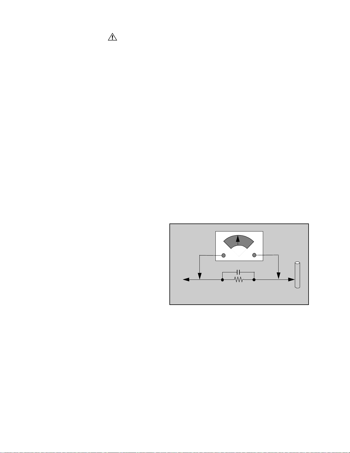
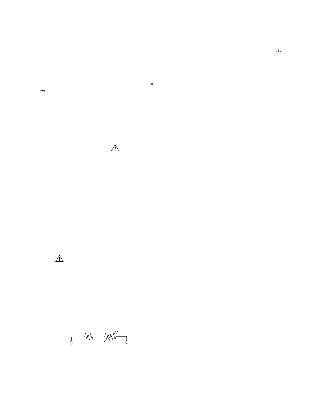
Leakage Current Hot Check (Fig. 1)
Plug the AC cord directly into the AC outlet. Do not use
an isolation transformer during the check.
Connect a 1.5kΩ 10 watt resistor in parallel with a
0.15µF capacitor between an exposed metallic part
and ground. Use earth ground, for example a
water pipe.
Using a DVM with a 1000 ohms/volt sensitivity or
higher, measure the AC potential across the resistor.
Repeat the procedure and measure the voltage
present with all other exposed metallic parts.
Verify that any potential does not exceed 0.75 volt
RMS. A leakage cu rrent te ster (such a Simp son M odel
229, Sencore Model P R57 or equiv alent) may be used
in the above procedure, in which case any current
measure must not exceed 0.5 milliamp. If any
measurement is out of the specified limits, there is a
possibility of a shoc k haz ar d and the Receiver mus t be
repaired and rechecked before it is returned to the
customer.
AC VOLTMETER
COLD
WATER
PIPE
(GROUND)
0.15µF
TO INSTRUMENT’S
EXPOSED METAL
PARTS
1500Ω,10 W
Figure 1. Hot Check Circuit
X-ray Radiation
WARNING: The potential source of X-ray radiation in the
TV set is in the High Voltage section and th e pictu re tube .
Note: It is important to use an accurate, calibrated
high voltage meter.
Set the brightness, picture, sharpness and color
controls to Minimum. Measure the High Voltage. The
high voltage should be 31.0 ± 1.0kV. If the upper limit is
out of tolerance, immediate service and correction is
required to insure safe operation and to prevent the
possibility of premature component failure.
Horizontal Oscillator Disable Circuit Test
This test must be performed as a final check before the
Receiver is returned to the customer. See Horizontal
Oscillator Disable Circuit Procedure Check in
this manual.
- 2 -
Important Safety Notice . . . . . . . . . . . . . . . . . . 2
Safety Precautions . . . . . . . . . . . . . . . . . 2
General Guidelines. . . . . . . . . . . . . . . . . 2
Leakage Current Cold Check. . . . . . . . . 2
X-ray Radiation. . . . . . . . . . . . . . . . . . . . 2
Horizontal Oscillator
Disable Circuit Test . . . . . . . . . . . . . 2
Service Notes. . . . . . . . . . . . . . . . . . . . . . . . . . . 4
Leadless Chip Component
(surface mount) . . . . . . . . . . . . . . . . 4
Component Removal . . . . . . . . . . . . . . . 4
Chip Component Installation . . . . . . . . . 4
How to Replace Flat-IC . . . . . . . . . . . . . 4
Horizontal Oscillator Disable Circuit . . . . 5
Receiver Feature Table . . . . . . . . . . . . . . . . . . . 6
Location of Controls (Receiver). . . . . . . . . . . . 7
Quick Reference Control Operation . . . . 7
Quick Reference. . . . . . . . . . . . . . . . . . . 7
Control Operation . . . . . . . . . . . . . . . . . . 7
Location of Controls (Remote). . . . . . . . . . . . . 8
Instructional Flow Chart for
Serviceman Mode . . . . . . . . . . . . . . . . . . . 24
Service Adjustments
(Electronic Controls). . . . . . . . . . . . . . . . . 27
Sub-Contrast Adjustment . . . . . . . . . . . 27
Sub-Brightness (B02) . . . . . . . . . . . . . . 27
Tint/Color Adjustment . . . . . . . . . . . . . . 27
PIP Sub-Contrast Adjustment (P03). . . 28
Color Temperature Adjustment. . . . . . . 28
Complete Adjustment . . . . . . . . . . . . . . 28
Horizontal Centering (D00). . . . . . . . . . 29
E-W PCC Adjustment (D0C). . . . . . . . . 29
Corner PCC Adjustment (D0B). . . . . . . 29
H-Size Adjustment (D0D) . . . . . . . . . . . 29
V-Size and V-Position Adjustment
(D01 & D06) . . . . . . . . . . . . . . . . . . 29
V-Linearity Adjustment (D03) . . . . . . . . 29
V-Correction Adjustment (D02). . . . . . . 30
MTS Circuit Adjustments . . . . . . . . . . . 30
Input Level Adjustment (M00). . . . . . . . 30
Stereo Separation Adjustment
(M01 & M02) . . . . . . . . . . . . . . . . . 30
Clock Adjustment (S07) . . . . . . . . . . . . 31
Service Adjus tments
(Mechanical Controls ) 31
Focus (part of T551). . . . . . . . . . . . . . . 31
Disassembly for Service. . . . . . . . . . . . . . . . . . 9
Back Cover. . . . . . . . . . . . . . . . . . . . . . . 9
A-Board - Main Chassis . . . . . . . . . . . . . 9
L-Board - CRT Output . . . . . . . . . . . . . . 9
Speakers . . . . . . . . . . . . . . . . . . . . . . . . 9
Keyboard Push Button Assembly. . . . . . 9
Disassembly for CRT Replacement . . . . 9
CRT Replacement . . . . . . . . . . . . . . . . . 9
Back Cover Removal . . . . . . . . . . . . . . 11
Chassis Service Adjustment Procedures . . . 12
140.0V B+ Voltage Confirmation . . . . . 12
Source Voltage Chart . . . . . . . . . . . . . . 12
High Voltage Check . . . . . . . . . . . . . . . 12
Purity and Convergence Procedure . . . . . . . 13
When the CRT or the Yoke is Replaced 13
Initial Center Static Convergence. . . . . 14
Purity Adjustment . . . . . . . . . . . . . . . . . 14
Dynamic Corvergence Adjustment. . . . 14
DY(YHC, YV, XV) Adjustment . . . . . . . 14
Permalloy Convergen ce Corrector
Strip (Part No. 0FMK014ZZ) . . . . . 15
DAF Adjustment . . . . . . . . . . . . . . . . . . 15
Serviceman Mode (Electronic Controls) 17
Exiting the Serviceman Mode. . . . . . . . 17
Entering Serviceman
Mode (Back-Open Method) . . . . . . 23
Audio Signal Path Block Diagram . . . . . . . . . 32
Video Signal Path Block Diagram . . . . . . . . . 33
IIC Connection . . . . . . . . . . . . . . . . . . . . . . . . . 34
Description of Connectors . . . . . . . . . . . . . . . 35
IC101 IN/OUT Pins and Functions (VCJ) . . . . 36
Component Identification . . . . . . . . . . . . . . . . 37
Parts List . . . . . . . . . . . . . . . . . . . . . . . . . . . . . 40
Schematics, Voltages and waveforms
L-Board Voltages,
PCB & schematics . . . . . . . . . . . . . . . . . 53
A-Board (Left Portion) . . . . . . . . . . . . . . . . . 54
A-Board (Right Portion). . . . . . . . . . . . . . . . 55
A-Board PCB. . . . . . . . . . . . . . . . . . . . . . . . 56
A-Board Voltages . . . . . . . . . . . . . . . . . . . . 57
D-Board schematics . . . . . . . . . . . . . . . . . . 58
D-Board PCB & voltages. . . . . . . . . . . . . . . 59
G-Board schematics . . . . . . . . . . . . . . . . . . 60
G-Board PCB & voltages . . . . . . . . . . . . . . 61
A-Board Waveforms . . . . . . . . . . . . . . . . . . 62
- 3 -
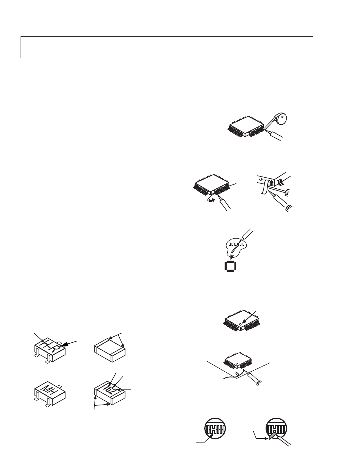
Service Notes
Note: These components are affixed with glue. Be careful not to break or damage any foil under the
component or at the pins of the ICs when removing. Usually applying heat to the component for a
short time while twisting with tweezers will break the component loose.
Leadless Chip Component
(surface mount)
Chip components must be replaced with identical chips
due to critical foil track sp acing. There are no holes in
the board to mount standard transistors or diodes.
Some chips capacitor or resistor board solder pads
may have holes thr ough the board, however the hole
diameter limits standard resistor replacement to 1/8
watt. Standard capacitor may also be limited for the
same reason. It is recommended that identical
components be used.
Chip resistor have a three digit numerical resistance
code - 1st and 2nd significant digits and a multiplier.
Example: 162 = 1600 or 1.6kΩ resistor, 0 = 0Ω (jumper).
Chip capacitors generally do not have the value
indicated on the capacito r. The color of the component
indicates the general range of the capa ci tan ce .
Chip transistors are identified by a two letter code. The
first letter indicates the type and the second l etter, the
grade of transistor.
Chip diodes have a two lette r i den tif ic ati on code as per
the code chart and are a dual diode pack with either
common anode or comm on cathode. Check the parts
list for correct di ode num ber.
Component Removal
1. Use solder wick to remove s older fr om compo nent
end caps or termin al.
2. Without pulling up, carefully twist the component
with tweezers to break the adhesive.
3. Do not reuse removed leadless or chip
components since they are subject to stress
fracture during removal.
Chip Component Installation
1. Put a small amount of solder on the board
soldering pads.
2. Hold the chip component against the soldering
pads with tweezers or with a min iat ur e all igato r cl ip
and apply heat to the pad area wi th a 30 watt iron
until solder flows. Do not appl y heat for more than
3 seconds.
TYPE
Chip Components
GRADE
c
SOLDER
CAPS
How to Replace Flat-IC
- Required Tools -
• Soldering iron • De-solder braids
• Iron wire or small awl • Magni fi er
1. Remove the solder from all of the pins of a Fla t-IC
by using a de-solder braid.
De-Solder
Flat-IC
2. Put the iron wire under the pins of the Flat-IC an d
pull it in the direction indicated while heating the
pins using a soldering iron. A small awl can be
used instead of the iron wire.
Iron
Wire
Pull
Soldering
Iron
Soldering
Iron
3. Remove the solder from all the pads of the Flat-I C
by using a de-solder braid.
Soldering
Iron
De-Solder
Braid
Flat IC
4. Position the new Flat-IC in pl ace (apply the pins of
the Flat-IC to the soldering pads where the pins
need to be soldered). Properly determine the
positions of the soldering pads and pins by
correctly aligning the polarity symbol.
Polarity Symbol
123.....
5. Solder all pins to the soldering pads using a fine
tipped soldering ir on .
Braid
Awl
b
ANODES
MH DIODE
e
TRANSISTOR
COMMON
CATHODE
SOLDER
CAPS
CAPACITOR
1ST DIGIT
RESISTOR
2ND DIGIT
MULTIPLIER
=1600 = 1.6k
Solder
Soldering
Iron
6. Check with a magnifier fo r solder bridge between
the pins or for dry joint betw een pins and solderi ng
pads. To remove a solde r bridge, use a de-solder
braid as shown in the figure below.
De-Solder
Braid
Solder
Bridge
Soldering
Iron
- 4 -
Service Notes (Continued)
IMPORTANT: To protect against possible damage to
the solid state devices due to arcing or static
discharge, make c ertain th at all groun d wires and CTR
DAG wire are secu re ly conne cted.
CAUTION: The power supply circuit is above earth
ground and the chassis cannot be polarized. Use an
isolation transformer when servicing the Receiver to
avoid damage to the test equipmen t or to the chassis.
Connect the test equipment to the proper ground () or
( ) when servicing, or incorrect voltages will be
measured.
WARNING: This Receiver has been designed to mee t
or exceed applicable safety and X-ray radiation
protection as specified by government agencies and
independent testing laboratories.
To maintain original product safety design standards
relative to X-ray radiation and shock and fire hazard,
parts indicated wit h the symbol on the schematic
must be replaced with ide ntical parts. Order p arts from
the manufacturer’s parts center using the parts
numbers shown in t his service manual, or provide the
chassis number and the part reference number.
For optimum performan ce and reliabi lity, all other parts
should be replaced with components of
identical specification.
Horizontal Oscillator Disable Circuit
This chassis employs a special circuit to protect
against excessive high voltage and beam current. If, for
any reason, the high voltage and beam current exceed
a predetermined level this protective circuit activates
and detunes the horizontal oscillator that limits the high
voltage. The over-voltage protection circuit is not
adjustable. However, if components indicated by the
symbol on the schematic in either the horizontal
sweep system or the over-voltage protection circuit
itself are changed, the operation of the circuit should
be checked using the following procedure:
Preparation
1. Connect Receiver to AC 120 Volts. Do not turn ON.
2. Connect HIGH VOLTAGE meter to 2nd anode
(H.V. button).
Note: Use cold ground( ) for
negative lead.
3. Connect the ammeter serial from the flyback anode
lead to the picture tube anode socket.
4. Prepare HHS jig to be connecte d between TPD50
and TPD51 as shown in Fig. 2.
Procedure
1. Open Connector A17.
2. Turn power ON and Apply a monoscope pattern.
3. Set current within 50-100µΑ
picture and bright controls.
4. Turn power OFF.
5. Connect HHS jig between TPD50 and TPD51 (VR
should be turn fully clockwise).
6. Turn power on.
7. Turn slowly the variable resistor to increase the
current until the horizontal sync frequenc y abruptly
increases indicating that the horizontal frequency is
just beginning to pull out of sync. Maintain the
current within
and bright controls
8. Observe the High Voltage meter. HIGH VOLTAGE
should read less than 40.2kV.
9. Turn power OFF, Remove HHS jig, HV meter,
ammeter and connect A17 c onne ctor.
10. Turn Power ON. Reset Picture and Brightness
controls. Confirm B+ 140V±1.5V with 120V AC
applied.
11.
IF HIGH VOLTAGE IS NOT WITHIN THE
:
by changing the
50-100µΑ by changing the pi cture
SPECIFIED LIMIT THE CAUSE MUST BE
DETERMINED BEFORE THE RECEIVER IS
RETURNED TO THE OWNER.
Equipment needed to check the disabled circuit:
1. DC Ammeter
2. High Voltage Meter (0- 50kV electrostatic)
3. Variac or Isolation Transformer
4. HHS Jig (See Fig. 2)
TPD50
100Ω
Figure 2. HHS Jig
1KΩ
TPD51
- 5 -

Receiver Feature Table
FEATURE\MODEL CT-32SX31E/UE/CE CT-36SX31E/UE/CE
Chassis NA8ML
Tu nning sy stem 96K
# of channels 181
Menu language Eng/Span/Fr
Closed Caption X
V-Chip (USA/CANADA) X
2RF X
Remote Model # EUR511500
Picture tube AMEC
Comb Filter 3 DIG
VM X
V/A norm X
Color Temp X
MTS/SAP/DBX X
BASS/BL/TRE Control X
AI Sound X
Surround X
SPATIALIZER/BBE BBE
Built-in audio power 10W/CH (10%)
# of speakers 2
A/V in (rear/front) 3(2/1)
S-VHS Input (rear/front) 1/1
Component Input
(Y,Pb,Pr)
Audio Out
(FAO: F, VAO: V)
EPJ/HPJ/MISC HPJ
Dimensions mm
(WxDxH) in
Weight (kg/lbs) 74.8/164.56 98.5/216.7
Power source (V/Hz) 120/60
Anode voltage 31.0kV ± 1.0kV
Video input jack
Audio input jack 500mV RMS 47kΩ
A-Board TNP2AH026 AB NIL
667.3x810x568
26.52x32.4x22.72
1V
p-p
1
F,V
747x936x610.5
29.88x37.44x24.42
75Ω, phon o jack
Specifications
are subject to
change without
notice or
obligation.
Dimensions and
weights are
approximate.
G-Board TNPA1670 AC
L-Board TNPA1 673 AB
D-Board TNP2AH027 AB NIL
Table 1. Receiver Features
- 6 -
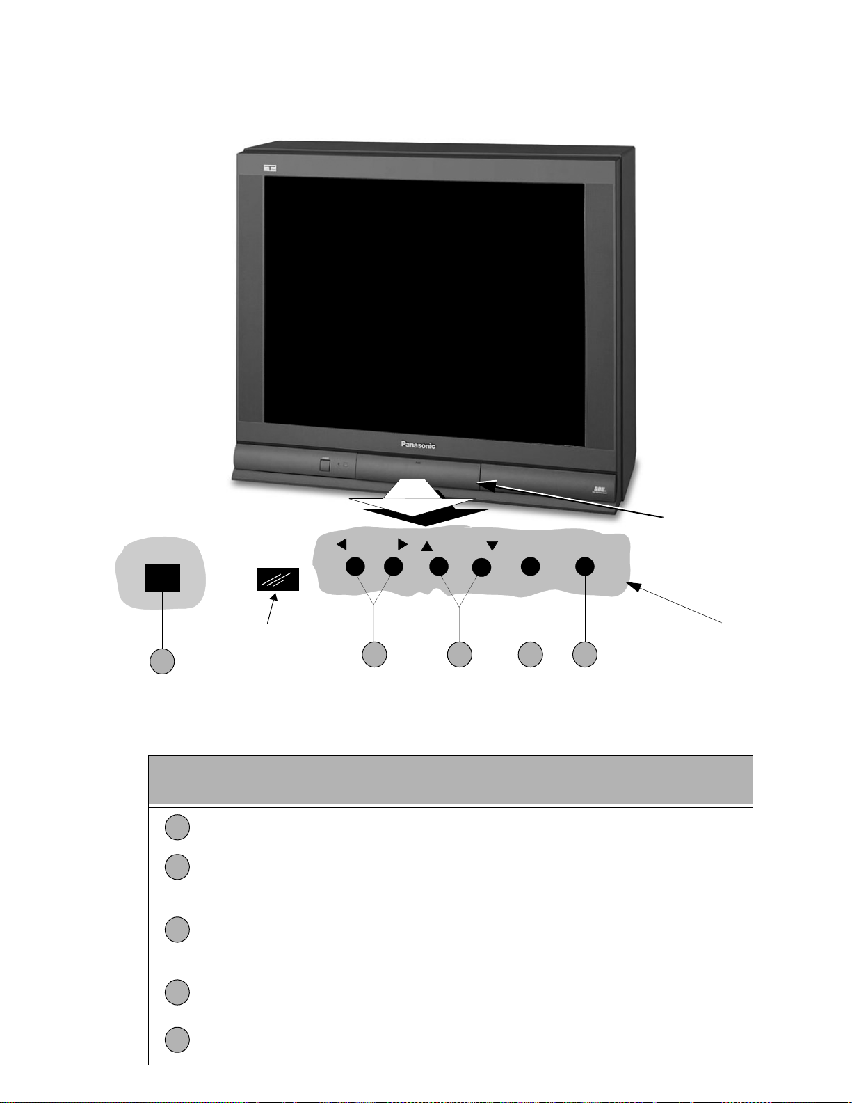
Location of Controls (Receiver)
POWER
1
Remote Control
Sensor
VOLUME
2 4 53
CHANNEL ACTION TV/VIDEO
Figure 3. Location of Controls (Receiver).
Quick Reference Control Operation
Quick Reference
Control Operation
1
Power Button - Press to turn ON or OFF.
Volume Buttons - Press to adjust Sound Level, or to adjust Audio Menus, Video
2
Menus, and select operating features when menus are displayed
Channel Buttons - Press to sele ct programme d channels. Pre ss to highlight d esired
features when menus are dis played. Also use to s elec t Cable Converte r box chan nels
3
after programming Remo te Control Infra-red codes ( the TV/AUX/CABLE switc h must
be set in CABLE position).
Front A/V Jacks
Controls Inside
front door
Action Button - Press to display Main Menu and access On Screen feature and
4
Adjustment Menus.
5
TV/Video Button - Press to select TV or Video Input.
- 7 -
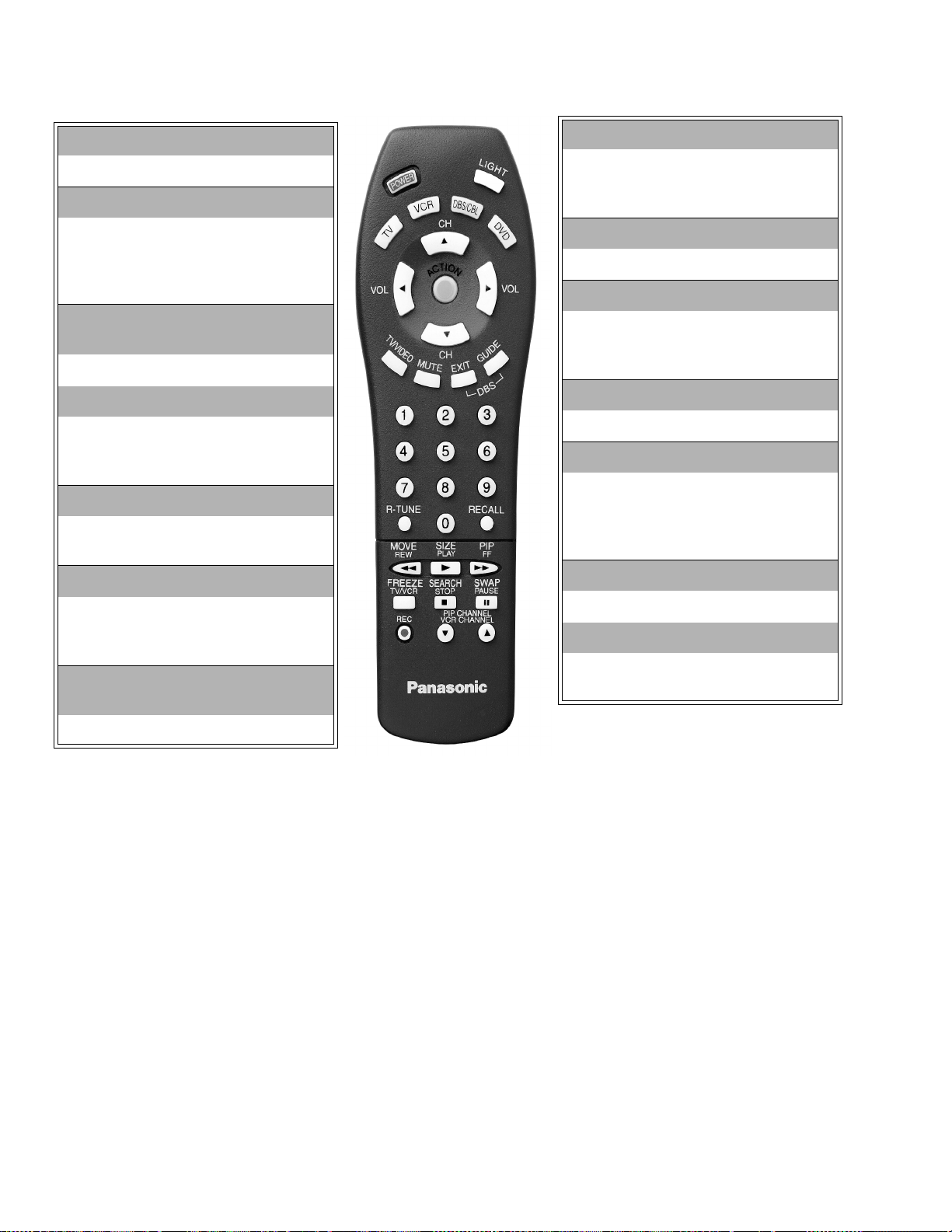
Location of Controls (Remote)
POWER Button
Press to turn ON and OFF.
MUTE Button
Press to mute sound.
A second press resumes sound.
Press also to access and delete
Closed Caption di splay.
VCR, DVD, LD/CD, AUX, TV, CBL,
DBS, RCVR
Component function buttons
VOL (volume) Buttons
Press to adjust TV sound level.
Use with Channel buttons to
navigate in menus.
R-TUNE (Rapid Tune) Button.
Press to switch to the pr ev io us
channel.
ACTION Button
Press to display Main Menu and
access or exit On Screen features
and Adjustment Menus.
REW, PLAY , FF, TV/VCR, STOP,
PAUSE, REC, VCR CHANNEL
MULTI Button
Programmable button that can
operate up to seven (7) functions at
once
TV/VIDEO Button
Press to select TV or Video input.
CH (channel) Buttons
Press to select channels.
Use with volume buttons to
navigate in menus.
DBS EXIT, DBS GUIDE
DBS function buttons.
RECALL Button
Press to display Time, status
of Sleep Timer, Channel,
Video mode and Channel
Caption (Station Identif ier ).
OPEN/CLOSE, SLOW, STILL
DVD function buttons.
“0” - “9”
Press numeric keypad to select any
channel.
Component function buttons.
EUR511500
Figure 4. Location of Controls (Remote).
- 8 -
Disassembly for Service
Back Cover
Remove all the screws marked with an arrow( )
from the back of the Receiver.
Note: Screw configuration, type, and number
of screws vary depending on the
model of the Receiver serviced and
the application; various models are
covered in this Manual. Use same
hardware when reassembling the
receiver.
• 4 screws at the top edge of the Receiver.
• 4 screw by the A/V jacks.
• 1 screw by the antenna jacks.
• 1 screw at each lower corner of the Receiver.
• 1 screw by the retainer plate of the AC power cord.
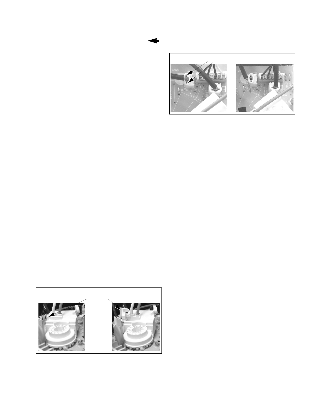
T o r elease screen GND cables from L-Board L11 & L12
connectors, insert a wire in both sides of connector and
pull upwards the cable, then remove the wire
(See Fig. 6)
Insert wire
Figure 6. L-Board Screen GND cables release
Pull cable upwards
A-Board - Main Chassis
The A-Board assembly rest on a chassis tray along
with the D-Board. Slide chassis tray out. Gently lift tray
and pull out. Disco nnect plug connectors; release wir e
ties and holders as required for complete chassis
removal.
1. A & D-Boards are secured to the chas sis tray with
five screws.
2. The A-Board is mated to the D-Board by three
flexible connect ors: A1, A2 & A3 (G1, G2 & G3 on
the G-Board, respectively). To remove either
boards, unplug the connectors on the A-Board.
Note: Some tie-wraps that s ecure the wire d ressings
may need to be unfastened for chassis
removal.
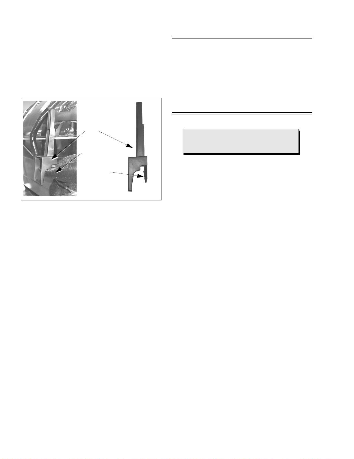
L-Board - CRT Output
Plugs into the socket on the CRT neck.
To remove this board, first unplug the board fr om
the CRT neck, then disconnect L1, L2 & L3
connectors, to disconnect the focus F1(Red Cable)
& F2(White Cable) cables, pu ll the ta b and re leas e
the cables, finally disconnect the screen cable from
the D-Board Fly-Back.
To reinsert back the cabl es, remembe r the original
position of cables, F1(re d cable) goes to A on the
CRT socket and F2(white cable) goes to B on the
CRT socket.
Press tab
leftward to
release cables
Pull cables
upwards
Speakers
Speaker is secured to the cabinet’s front with 4
screws.
Keyboard Push Button Assembly
Fastened to the inside of the cabinet front.
Disassembly for CRT Replacement
1. Discharge the CRT as instructed in the Safety
Precautions (see page 2).
2. Disconnect the yoke (DY) plug, degaussing coil
(DEG) plug and the CRT 2nd anode button from
the board.
3. Remove the L-Board from the CRT socket and
unplug the black wires (CRT dag ground) L11 &
L12.
4. Lift the Main Chassis (A-Board) and all mounted
boards completely out with the CRT Board attached.
CRT Replacement
1. Perform Disassembly for CRT Replacement
procedure.
2. Insure that the CRT H.V. Anode button is
discharged before handling the CRT. Read the
Safety Prec autions (see page 2) on handling the
picture tube.
3. Remove the components from the CRT neck and
place the cabinet face down on a soft pad.
4. Note the original order for the CRT mounting
hardware as they are remove from the CRT
mounting brackets at each c orner of the CRT.
5. Remove the CRT with the dega ussing co il and th e
dag ground braid attached.
Figure 5. F1 & F2 cables release
- 9 -
Note:
After servicing the receiver, remember
to dress the cables, as shown above.
Disassembly for Service (Continued)
Note: To remove the four brackets holding
the degauss coil from the corners of
the CRT, first remove the CRT from
the cabinet, then remove the Brackets
by pressing the tab o n the bracket and
pull upwards. These Brackets are
included in the Degauss Coil Kit, for
part number, please see parts list
section (See Fig. 7).
Degaussing
Coil
Bracket
Degaussing
Coil
Press tab
Then Pull
Upwards
Note: Reuse all the clampers a nd mounting
brackets from the degaussing c oil and
screen, and when remounting the
degaussing coil assure that is not
touching the speakers, this can be
done by placing some tape
(See Fig. 7), this may cause mask
vibration. The mounting brackets and
clampers are not supplied with the
replacements.
Important Notice:
When ordering the CRT, please order CRT
and CRT KIT also. Please see parts list
section for part numbers
Figure 7. Brackets removal
6. Note the original locations and mounting of the
degaussing coil and the dag ground assembly to
insure proper reinstallation on the replacement
CRT.
To remove and remount the degaussing coil:
The degaussing co il is held in place by clampers
fastened to the CRT corner ears. These c lampers
must be installed onto the replacement CRT prior
to mounting the degaussing coil.
To remove and remount the dag ground braid:
a.Unhook the coil sprin g from the bottom corners
of the CRT ears.
b.Release the braid loop from the upper corners of
the CRT ears.
7. Mount the dag ground braid on the replacement
CRT. Position the degaussing coil with new ties.
Dress coil as was on the original CRT.
8. Replace the components on CRT neck and
reinstall into cabinet. Verify that all ground wires
and circuit board plugs get connected.
- 10 -
 Loading...