

Panasonic CT-32SX12C, CT-36SX12C Operating Instructions Manual

®
Color Television
Operating Instructions
CT-32SX12C CT-36SX12C
TQB2AA0390-0 20804
PRINTEDINUSA
For assistance, please call: 1-800-211-PANA (7262) or
send e-mail to: consumerproducts@panasonic.com (USA only)
WARNING
RISK OF ELECTRIC SHOCK
DO NOT O PEN
WA RNING : To reduce the risk of electric shock do not remove cover or back.
No user-serviceabl eparts inside. Refer servicing to qualified service personnel.
WARNING: TO REDUCE THE RISK OF FIRE OR ELECTRIC SHOCK, DO
FCC CAUTION:
ENVIRONMENTAL NOTICE:
The lightning flash with arrow
head within a triangle is
intended to tell the user that
parts inside the product are a
risk of electric shock to
persons.
The exclamation point within a
triangle is intended to tell the
user that important operating
and servicing instructions are
in the papers with the
appliance.
NOT EXPOSE THIS APPARATUS TO RAIN OR MOISTURE.
ANY CHANGES OR MODIFICATIONS TO THIS TV
RECEIVER NOT EXPRESSLY APPROVED BY
MATSUSHITA ELECTRIC CORPORATION OF AMERICA
COULD CAUSE HARMFUL INTERFERENCE, WHICH
WOULD VOID THE USER’S AUTHORITY TO OPERATE
THIS EQUIPMENT.
THIS PRODUCT UTILIZES BOTH A CATHODE RAY TUBE (CRT) AND
OTHER COMPONENTS THAT CONTAIN LEAD. DISPOSAL OF THESE
MA TERIALS MAY BE REGULATED IN YOUR COMMUNITY DUE TO
ENVIRONMENTAL CONSIDERATIONS. FOR DISPOSAL OR RECYCLING
INFORMATION PLEASE CONTACT YOUR LOCAL AUTHORITIES, OR THE
ELECTRONICS INDUSTRIES ALLIANCE: <HTTP://WWW.EIAE.ORG.>
Manufactured under license from BBE Sound, Inc.
Licensed by BBE Sound, Inc. under USP4638258 and 4482866.
High Definition Sound
BBE and BBE symbol are registered trademarks of BBE Sound, Inc.

Table of Contents
Congratulations.........................................................2
Customer Record ......................................................................2
Care and Cleaning.....................................................................2
Specifications ............................................................................2
Installation..................................................................3
Television Location....................................................................3
Optional Cable Connections......................................................3
AC Power Supply Cord..............................................................3
Cable / Antenna Connection......................................................3
Feature Chart .............................................................4
Auto Set Up Menu......................................................5
Optional Equipment Connections ...........................6
VCR Connection........................................................................6
Front Control Panel ...................................................................6
Cable Box Connection...............................................................7
VCR and Cable Box Connection...............................................7
Program Out Connection (PROG OUT)....................................8
Amplifier Connection (TO AUDIO AMP)....................................8
Digital TV - Set-Top Box or DVD Player Connection.................9
Remote Control Operation .....................................10
Battery Installation...................................................................10
Mode Operational Key Chart ..................................................11
Programming the Remote .......................................................12
Component Codes...................................................................13
Icon Menu Navigation .............................................15
Main Menu Icons......................................................16
Icon Menus..............................................................................16
Icon Menu Operation...............................................17
Set Up......................................................................................17
Picture .....................................................................................19
Timer .......................................................................................20
Audio .......................................................................................21
Channels .................................................................................22
Lock.........................................................................................23
V-Chip Menu Operation...........................................24
Troubleshooting Chart............................................29
Limited Warranty .....................................................30
Index .........................................................................31
T
ABLE OFCONTENTS
Read these instructions completely before operating television.
Contents are subject to change without notice or obligation.
Copyright 2002 by Matsushita Electric Corporation of America. All rights reserved.
Unauthorized copying and distribution is a violation of law.
1
C
ONGRATULATIONS
Congratulations
Your new Panasonic Tau television is designed to provide state-of-the-art picture quality and features an innovative pure
flat picture tube. The new dolphin gray cabinet with compact, elegant styling is designed to give you many years of
enjoyment. It was thoroughly tested and tuned at the factory for best performance.
Customer Record
The model and serial number of this product are located on the back of the television. You should note the model and serial
number in the space provided and retain as a permanent record of your purchase. This will aid in identification in the event
of theft or loss.
Model
Number
Serial
Number
Care and Cleaning
Screen (Turn TV Off)
• Use a mild soap solution or window cleaner with a soft clean cloth. DO NOT USE ABRASIVE CLEANERS.
• Avoid excessive moisture and wipe dry.
Note: Do not spray any type of cleaning fluid directlyon the screen.
Cabinet and Remote Control
For cabinets and remote control, use a soft cloth dampened with water or a mild detergent solution. Avoid excessive moisture and
wipe dry.
Do not use benzene, thinner or other petroleum based products.
Specifications
Power Source
CT-32SX12C (2.7A)
CT-36SX12C (2.7A)
Channel Capability - 181 VHF-12; UHF-56; Cable-113
Video Input Jacks 1Vp-p, 75 Ohm, Phono Jack Type
Audio Input Jacks 500mV RMS 47K Ohm
Audio Output Jacks 0-2.0V RMS 4.7K Ohm
Componentinput(Y/PB/PR)
S-Video Input Jacks S-Video (Y-C) Connector
Specifications are subject to change without notice or obligation.
120V AC, 60Hz
75 Ohms, Phono Jack Type
2
I
NSTALLATION
Installation
Television Location
Follow these recommendations before deciding the location of your television.
Avoid excessive sunlight or bright lights, including reflections.
Keep away from excessive heat or moisture. Inadequate ventilation may cause internal component failure.
Fluorescent lighting may reduce remote control transmitting range.
Keep away from magnetic equipment, including motors, fans and external speakers.
CAUTION: Use this television receiver only with the cart, stand, tripod, bracket, or table specified by the manufacturer, or
sold with the apparatus. When a cart is used, use caution when moving the cart/apparatus combination to avoid injury from
tip-over. In order to avoid injury to children, never place your television receiver on a piece of furniture that is capable of
being tilted by a child leaning on it, pulling on it, standing on it, or climbingon it.
CT-32SX12C:
CAUTION: This television receiver for use only with PANASONIC TY-32SX31P stand. Use with other carts (or stands) is capable
of resulting in instability causing possible injury.
CT-36SX12C:
CAUTION: This television receiver for use only with PANASONIC TY-36SX31P stand. Use with other carts (or stands) is capable
of resulting in instability causing possible injury.
Optional Cable Connections
Shielded audio and video cables should be used between components. For best results:
Use 75-ohm coaxial shielded cables.
Use appropriate input and output connectors that match your component connectors.
Avoid long cables to minimize interference.
AC Power Supply Cord
CAUTION: TO PREVENT ELECTRIC SHOCK MATCH WIDE BLADE OF PLUG TO WIDE SLOT OF AC OUTLET
AND FULLY INSERT. DO NOT USE A PLUG WITH A RECEPTACLE OR OTHER OUTLET UNLESS THE BLADE
CAN BE FULLY INSERTED TO PREVENT BLADE EXPOSURE.
PROTECT POWER CORDS FROM BEING WALKED ON, ROLLED OVER, CRIMPED, BENT OR PINCHED,
PARTICULARLYAT PLUGS, CONVENIENCE RECEPTACLES, AND THE POINT WHERE THEY EXIT FROM THE APPARATUS.
Polarized plug
Cable / Antenna Connection
For proper reception, either a cable or antenna connection is required.
Cable Connection
Connect the cable supplied by your local cable company.
Note: A cable converter box may be required for proper reception. Check with your local cable company for
compatibility requirements.
Antenna Connection
• For proper reception of VHF/UHF channels, an external antenna is required. For best reception, an
outdoor antenna is recommended.
• Connect home antenna to ANT on the back of television.
Note: Cable Mode is preset at the factory. Antenna users must change to TV mode in the Set Up Menu under
Prog Chan.
Incoming Cable from
Cable Company
75 Ohm VHF/UHF
on back of TV
IncomingCablefrom
Home Antenna
3
F
EATURECHART
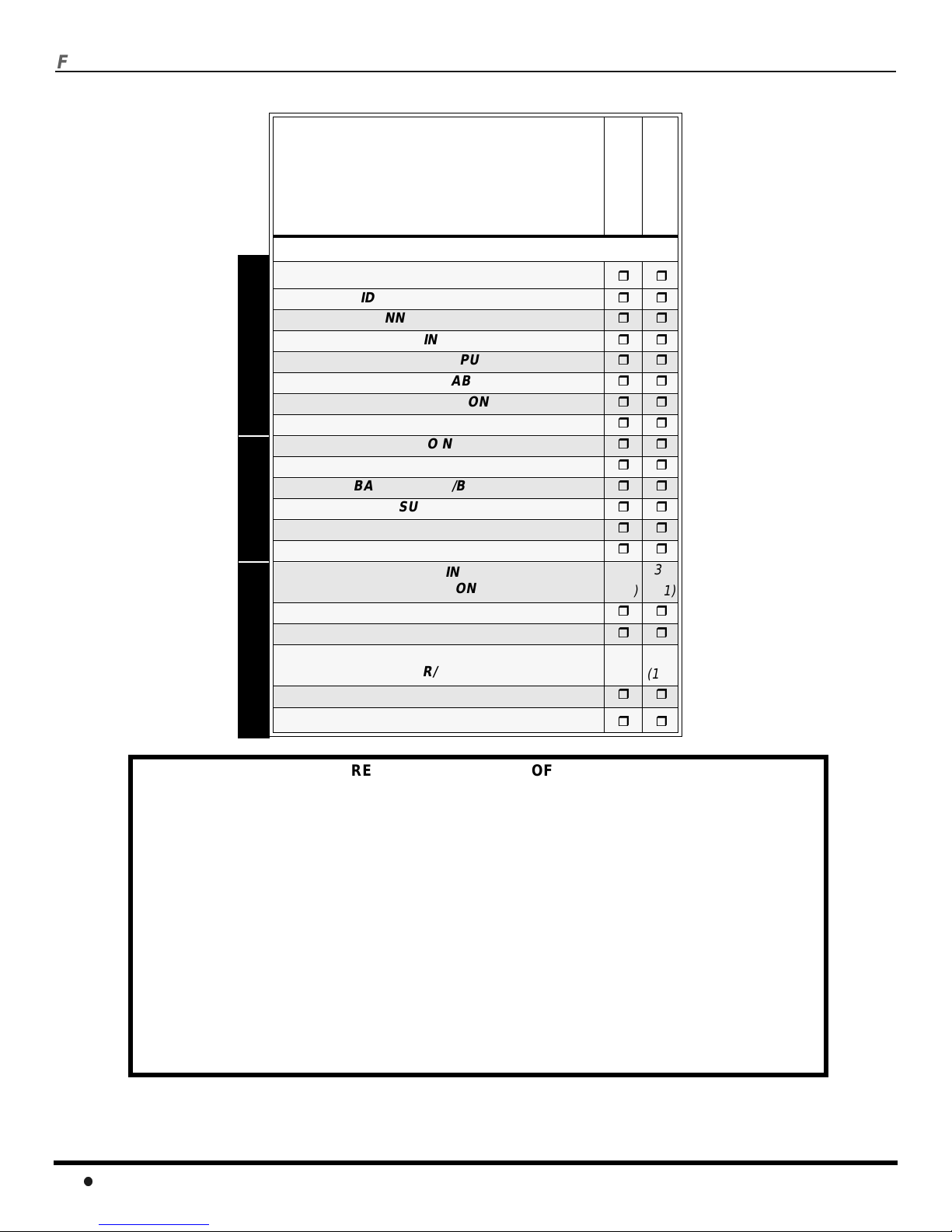
Feature Chart
MODELS
CT-36SX12C
CT-32SX12C
Features
MENU LANGUAGE ENG/SPAN/FR
VIDEO PICTURE MEMORY
CHANNEL INFO BANNER
VIDEO INPUT SKIP
75 OHM INPUT
V-CHIP CAPABILITY
CLOSED CAPTIONING
VIDEO NORM
AUDIO NORM
STEREO
BASS/TREBLE/BALANCE
SURROUND
AI SOUND
BBE
A/V IN
(REAR/FRONT)
AUDIO OUT
A/V PROGRAM OUT
S-VIDEO INPUT
A/V JACKS AUDIO SPECIAL FEATURES
(REAR/FRONT)
COMPONENT VIDEO INPUT
HEADPHONE JACK
3
(2/1)3(2/1)
2
(1/1)2(1/1)
IMPORTANT INFORMATION REGARDING THE USE OF VIDEO GAMES, COMPUTERS, OR
OTHER FIXED IMAGE DISPLAYS.
WARNING: The marking or retained image on the picture tube resulting from viewing fixed
image is not an operating defect and as such is not covered by Warranty.
This television is designed to display constantly moving images on the screen. Continuous viewing
of stationary images such as letterbox pictures on standard screen TVs (with top/bottom bars), nonexpanded standard (4:3) pictures on wide screen TVs (with side bars shown on each side of an
image), stock market report bars (ticker running at the bottom of the screen), video game patterns,
fixed scoreboards, bright station logos, on-line (Internet) or repetitive computer style patterns should
be limited.
The extended use of fixed image program material can cause permanent picture tube damage,
shown as a “shadow image” viewable on normal programs. This type of irreversible picture tube
deterioration can be limited by performing the following steps:
• Do not display the fixed image for extended periods of time.
• Turn the power off when not in use.
4

A
UTOSETUPMENU
Auto Set Up Menu
For your convenience, Auto Set up menu will be displayed on screen when the set is turned on for the first time. If needed,
follow the menus and procedures for setting up the features.
IDIOMA/LANGUE - To change menu language to ENGLISH, SPANISH or FRENCH.
FIRST PLEASE
CONNECT THE ANTENNA
IDIOMA/LANGUE ENGLISH
AUTO PROGRAM
GEOMAGNETIC CORRECTION
TILT CORRECTION
MODE - To select TV (antenna) or CABLE mode depending on the signal source.
IDIOMA/LANGUE ENGLISH
AUTO PROGRAM
GEOMAGNETIC CORRECTION
TILT CORRECTION
AUTO SET UP
PRESS ACTION TO EXIT
FIRST PLEASE
CONNECT THE ANTENNA
AUTO SET UP
PRESS ACTION TO EXIT
u
CABLEMODE
u
u
u
u
u
CABLEMODE
u
u
u
u
Press VOLto select English, Spanish or French.
Press VOLto select TV or CABLE.
AUTO PROGRAM - To automatically program all channels with a signal.
FIRST PLEASE
CONNECT THE ANTENNA
IDIOMA/LANGUE ENGLISH
AUTO PROGRAM
GEOMAGNETIC CORRECTION
TILT CORRECTION
GEOMAGNETIC CORRECTION - This feature is used to adjust discoloration of the picture due to the earth’s
AUTO SET UP
PRESS ACTION TO EXIT
u
CABLEMODE
u
u
u
u
Press VOLto start Auto Programming.
magnetic field in the area.
FIRST PLEASE
CONNECT THE ANTENNA
IDIOMA/LANGUE ENGLISH
AUTO PROGRAM
GEOMAGNETIC CORRECTION
TILT CORRECTION
TILT CORRECTION - This feature is used to adjust the tilt of the picture due to earth’s magnetic field in the area.
IDIOMA/LANGUE ENGLISH
AUTO PROGRAM
GEOMAGNETIC CORRECTION
TILT CORRECTION
AUTO SET UP
PRESS ACTION TO EXIT
FIRST PLEASE
CONNECT THE ANTENNA
AUTO SET UP
PRESS ACTION TO EXIT
u
CABLEMODE
u
u
u
u
u
CABLEMODE
u
u
u
u
Press VOLto display adjustment menu.
PressVOL or VOLto adjust discoloration in
picture.
Press VOLto display adjustment menu.
PressVOL or VOLto adjust picture tilt.
GEOMAGNETIC CORRECTION
- - - - - - - - - - - - - - - - - -
0
TILT CORRECTION
0
l
t
TO ADJUST
PRESS ACTION TO EXIT
- - - - - - - - - - - - - - - - - -
l
t
TO ADJUST
PRESS ACTION TO EXIT
u
u
5
O
O
PTIONALEQUIPMENTCONNECTIONS
Optional Equipment Connections
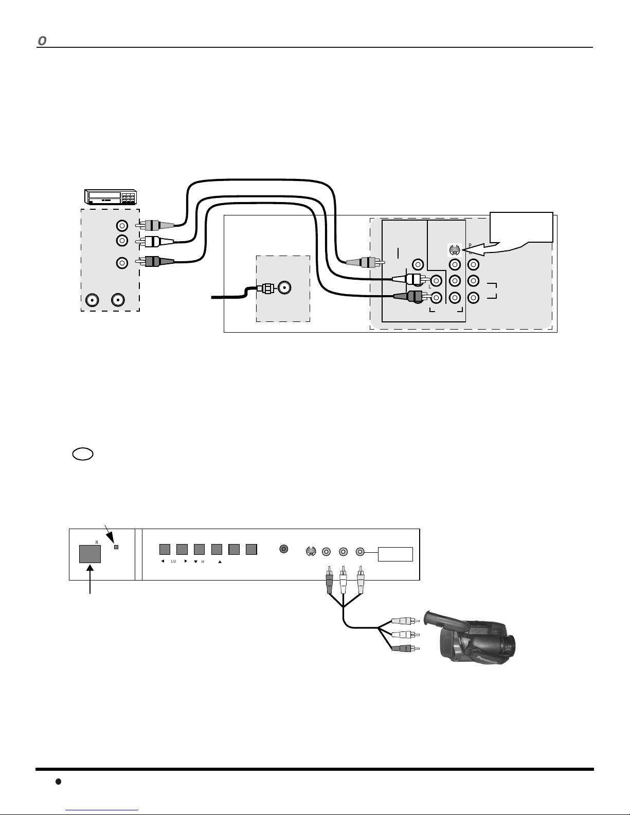
VCR Connection
VCRs, video disc players, video game equipment, and DSS equipment can also be connected to the video inputs. See the
optional equipment manual for more information.
Note: Input 1 is a dual-purpose input. It is primarily intended for connection with 480i devices such as a DVD player using the
YP
video sources such as a VCR, using only the Y/Video jack and Audio L & R jacks. The on-screen label will display
Component or Video1 dependingon which sourceis connected.
VCR
VIDEO OUT
AUDIO OUT
ANT INANT OUT
CABLES NOT S UPPL IED
component video jacks and Audio L & R jacks. However, it can also be connected to conventional composite
BPR
TERMINALS ON BACK OF THE TV
INPUT 1 INPUT 2
L
R
Incoming
Cable
ANT
COMPONENT
VIDEO INPUTS
VIDEO/Y
P
B
P
R
VIDEO
L
R
S-VIDEO
AUDIO
L
R
Use either the
S-Video or Video
connection.
PROG
OUT
L
TO AUDIO AMP
R
Note: The remote control must be programmed with suppliedcodes to operate the VCR.
Procedure
1. Connect equipment as shown to rear Audio/Video input jacks.
2. Select the Video mode by pressing TV/VIDEO button.
3. Operate optional equipment as instructed in equipment manual.
Front Control Panel
TV/VIDE
Press to select VIDEO 3 input mode.
Note: The front control panel located behind the customer control door can be used to access menus and switch video mode when
the remote control is not available.
ON/OFF INDICATOR
POWER
POWER ON/OFF
Note: The S-VIDEO connection provides higher quality picture. It
overrides VIDEO 3 connections. Use INPUT 3, AUDIO L
and R with S-VIDEO connection.
Note: The ON/OFF indicator LED (red) will be lit when set is on.
VOLUME
CHANNEL
ACTION TV/VIDEO
HPJ
S-VIDEO
VIDEO L-AUDIO-R
INPUT 3
CAMCORDER
A second VCR, Camcorder, a video disc player, video game equipment or DSS equipment can also be connected to the
video inputs. See the optional equipment manual for details.
Procedure
1. Connect equipment to front Audio/Video input jacks.
2. Press TV/VIDEO button to select VIDEO 3 input mode.
3. Operate optional equipment as instructed in equipment manual.
6
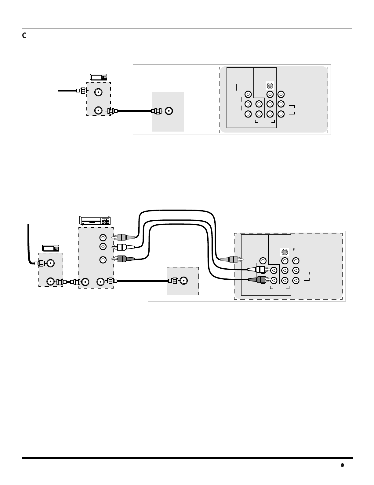
Cable Box Connection
Follow this diagram when connecting your television to a cable box only.
O
PTIONALEQUIPMENTCONNECTIONS
TERMINALS O N BACK OF THE TV
Incoming
Cable
CABLE BOX
ANT IN
ANT O UT
ANT
INPUT 1 INPUT 2
COMPONENT
VIDEO INPUTS
VIDEO/Y
P
B
P
R
CABLES NOT SUPPLIED
Note: The remote control must be programmed with supplied codes to operate the cable box.
Viewing a premium (scrambled) cable channel
Procedure
1. Tune the television to Channel 3 or 4 dependingon the RF out setting of the cable box.
2. Using the cable box, tune to the premium cable channel you want to view.
VCR and Cable Box Connection
Follow this diagram when connecting your television to both a VCR and a cable box.
Incoming
Cable
CABLE BOX
ANT IN
ANT OUT
VCR
VIDEO OUT
L
AUDIO OUT
R
ANT OUTANT IN
CABLES NOT S UPPLIED
ANT
TERMINALS ON BACK OF THE TV
INPUT 1 INPUT 2
COMPONENT
VIDEO INPUTS
VIDEO/Y
VIDEO
L
R
P
B
P
R
S-VIDEO
AUDIO
VIDEO
L
R
L
R
S-VIDEO
AUDIO
PROG
OUT
L
TO AUDIO AMP
R
PROG
OUT
L
L
TO AUDIO AMP
R
R
Note: The remote control must be programmed with suppliedcodes to operate the VCR and cable box.
Viewing a premium (scrambled) cable channel
Procedure
1. Tune the television to CH 3 or CH 4 depending on the Cable box RF out.
2. Using the cable box, tune to the premium cable channel you want to view.
Recording a premium (scrambled) cable channel
Procedure
1. Press the TV/VIDEO button on the remote control to s elect the video i nput (VIDEO 1, VIDEO 2, etc.) connected to your VCR.
2. Turn the VCR ON.
3. Tune the VCR to Channel 3 or 4, depending on your VCR.
4. Using your cable box, tune to the premium cable channel you want to record.
5. Begin recording.
7
O
PTIONALEQUIPMENTCONNECTIONS
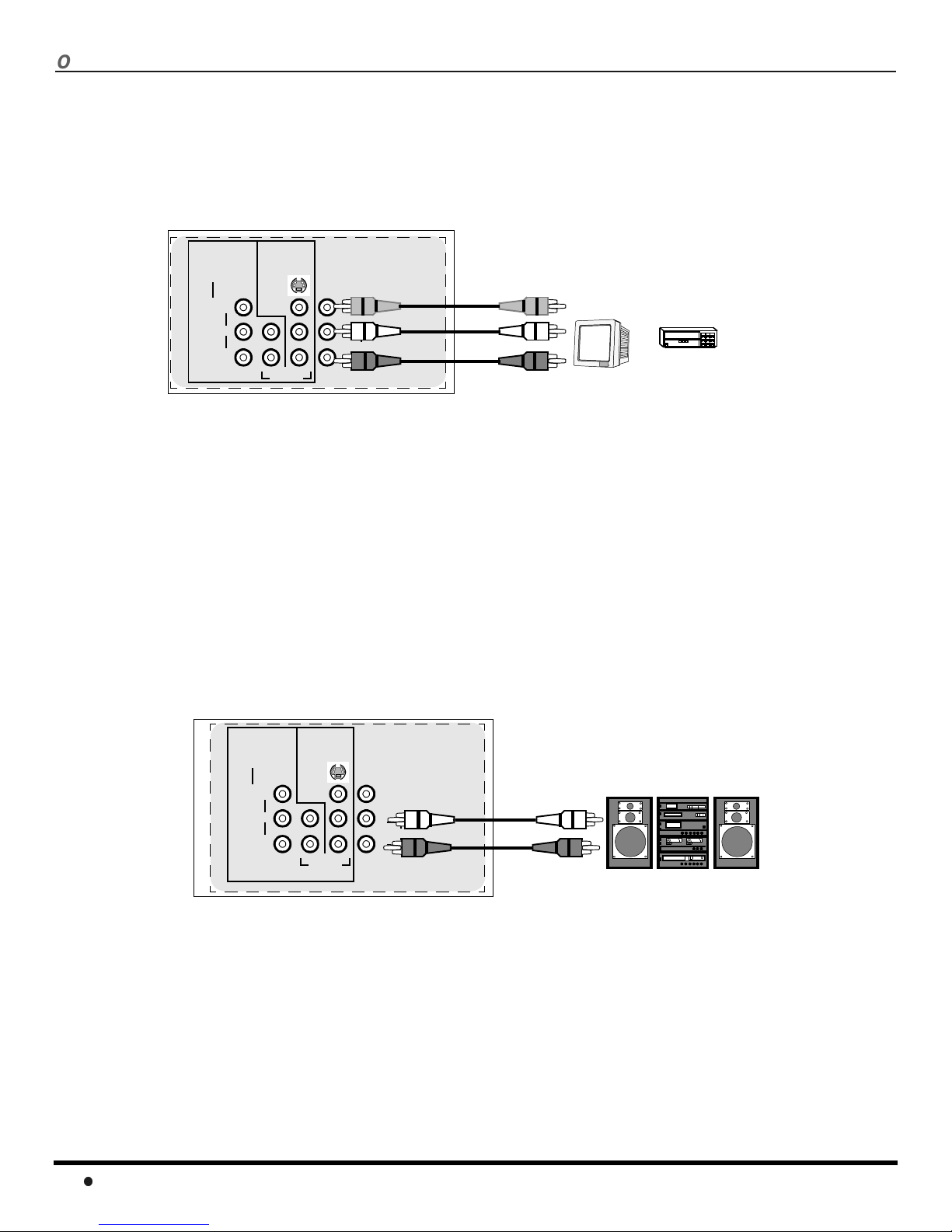
Program Out Connection (PROG OUT)
To use the television audio and video with optional equipment, connect the PROG OUT and TO AUDIO AMP connections on the back of
the television.
Notes:
• When a component input video signal is connected to Video 1 (Y,P
) terminals, and the TV main picture is Component, the P rogram
B,PR
output video will be luminance signal (no color).
• When S-Video input signal is used for TV main picture, the Program output video signal will be luminance signal (no color).
CONNECTIONS ON BACK OF TV
INPUT 1 INPUT 2
COMPONENT
VIDEO INPUTS
VIDEO/Y
P
B
P
R
VIDEO
L
R
S-VIDEO
AUDIO
PROG
OUT
L
R
L
TO AUDIO AMP
R
CABLES NOT SUPPLIED
MONITOR
VCR
OR
Procedure
1. Connect optional equipment to PROG OUT and TO AUDIO AMP terminals.
2. PROG OUT terminal display is the same as onscreen display.
3. See optional equipment manual for further instructions for recording and monitoring.
Amplifier Connection (To Audio Amp)
Connect to an external audio amplifier input for listening to a stereo system.
Note: TO AUDIO AMP terminals cannot be connected directly to external speakers.
Audio Adjustments
1. Select TV SPEAKERS ON from AUDIO menu.
2. Set amplifier volume to minimum.
3. Adjust TV volume to desiredlevel.
4. Adjust amplifier volume to match the TV.
5. Select TV SPEAKERS OFF&VAO from AUDIO menu.
6. Volume, mute, bass, treble and balance are now controlled from the TV.
Note: In OFF&FAO the volume is controlled by the external amplifier.
TERMINALS ON BACK OF TV
INPUT 1 INPUT 2
COMPONENT
VIDEO INPUTS
VIDEO/Y
P
B
P
R
VIDEO
L
R
S-VIDEO
AUDIO
L
R
PROG
OUT
L
TO AUDIO AMP
R
External Amplifier
CABLES NOT SUPPLIED
8
O
PTIONALEQUIPMENTCONNECTIONS
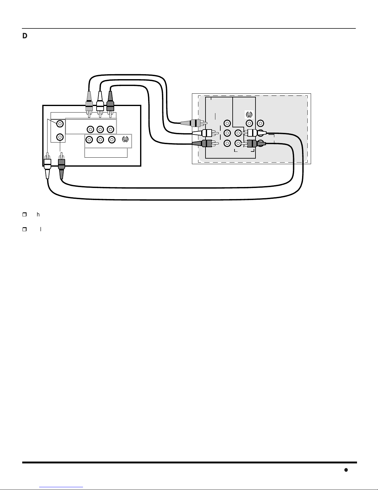
Digital TV - Set-Top Box (DTV-STB) or DVD Player Connection
Use this diagram to connect the Panasonic DTV -STB (Digital TV-Set-Top Box) to the back of your TV.
TERMINALS ON BACK OF DTV-STB OR DVD PLAYER
CABLES NOT SUPPLIED
DIGITAL TV OUTPUT
MAIN
VIDEO
R-AUDIO-L
B
-VIDEO
PRP
Y
R-AUDIO-L
NTSC OUTPUT
S-VIDEO
INPUT 1 INPUT 2
COMPONENT
VIDEO INPUTS
VIDEO/Y
TERMINALS ON BACK OF TV
S-VIDEO
VIDEO
P
B
L
P
R
R
AUDIO
L
R
PROG
OUT
L
TO AUDIO AMP
R
Notes:
There are three video inputs, Y, PB,andPR. Separate component color inputs provide luminance and color separation. Use the
L (left) and R (right) audio inputs.
Select DTV-STB to 480i output mode. TV set can receive 480i signal only.
9
R
EMOTECONTROLOPERATION
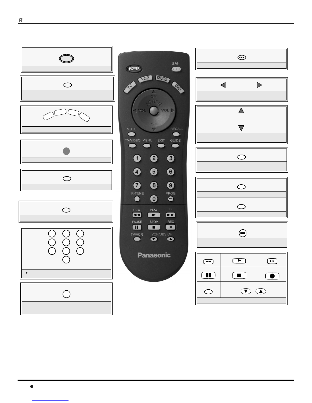
Remote Control Operation
POWER
POWER
Press to turn ON and OFF.
MUTE
Press to mute sound. Press to display and
cancel CC (Closed Caption).
D
B
S
R
/
C
V
V
T
Press to select remote operation.
C
B
L
D
V
D
ACTION
Press to access menus.
TV/VIDEO
Press to select TV or Video mode.
MENU
SAP
Press to access second audio program.
VOLVOL
Press to adjust TV sound and navigate in
menus.
CH
CH
Press to select next or previous channel an d
navigate in menus.
RECALL
Press to display time, channel, sleep timer,
and other options.
EXIT
DBS functions button.
GUIDE
Press to access DBS or DVD menus.
1 2
4
7
3
5
6
8
9
0
Press numeric keypad to select any chann el.
R-TUNE
Press to switch to previously viewed
channel or video mode.
Battery Installation
Use two AA batteries:
Remove battery cover by pushing in and up near arrow.
Install batteries matching (+) and (-) polarity signs.
Replace the battery cover.
EUR7613Z10
DBS functions button.
PROG
Press to enter minor number in a compou nd
number (DBS mode only).
REW
PAUSE
TV/VCR
Component function buttons
PLAY
STOP
VCR /DBS CH
Precautions
• Replace batteries in pairs.
• Do not mix battery types (zinc carbon
with alkaline).
• Do not recharge, heat, short-circuit,
disassemble, or burn batteries.
FF
REC
Note:
Incorrect installation can cause battery leakage and
corrosion that will damage the Remote Control.
10
R
EMOTECONTROLOPERATION
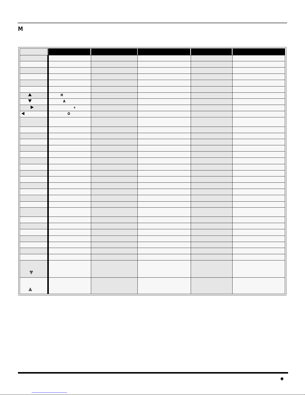
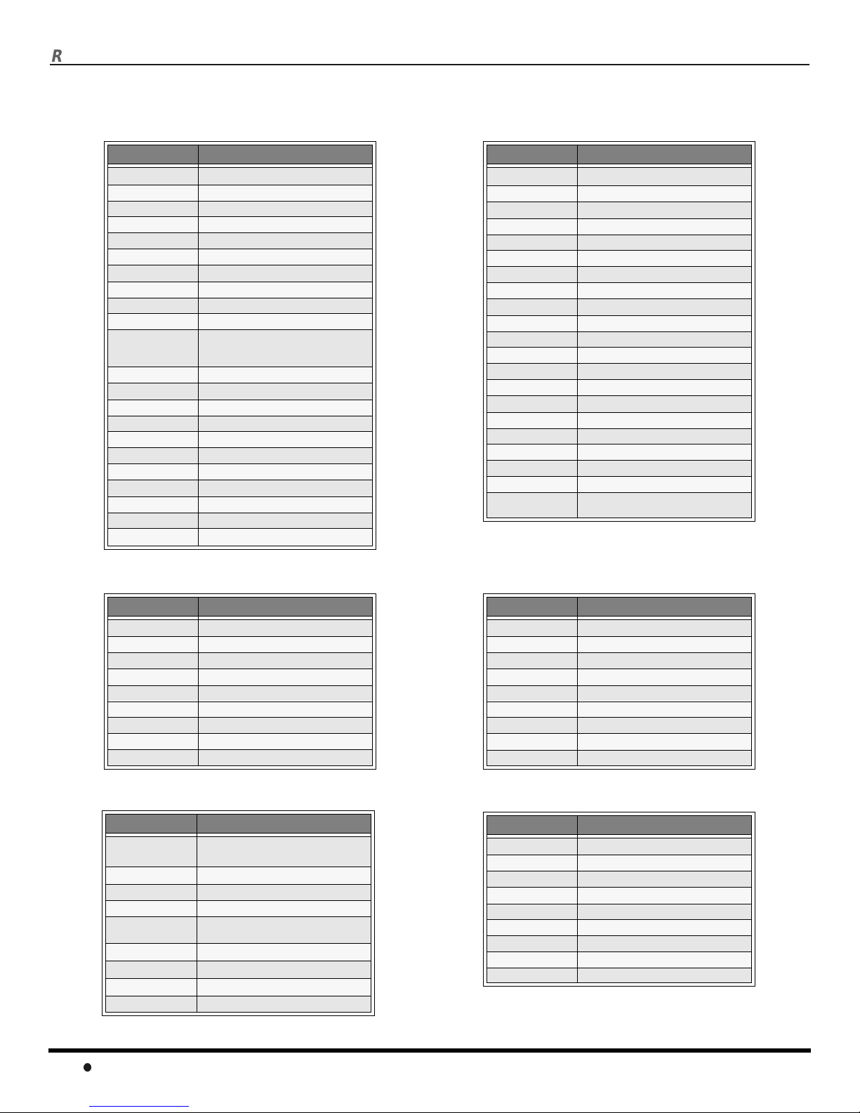
Mode Operational Key Chart
This chart defines the keys that are operational in the selected component modes (TV, VCR, DBS, CABLE or DVD) after
programming (if needed).
KEY NAME
POWER
SAP
MUTE
TV/VIDEO
MENU
ACTION
CH
CH
VOL
VOL
RECALL
EXIT
GUIDE
PROG
1
2
3
4
5
6
7
8
9
0
R-TUNE
<<REW
PLAY
FF >>
PAUSE
STOP
RECORD
TV/VCR
VCR/DBS
CH
TV MODE CABLE MODE DBS MODE VCR MODE DVD MODE
POWER POWER POWER POWER POWER
SAP ON/OFF - - - -
MUTE TV MUTE TV MUTE TV MUTE TV MUTE
INPUT SWITCH TV INPUT SWITCH TV INPUT SWITCH TV INPUT SWITCH TV INPUT SWITCH
- - DBS MENU - -
ACTION - DBS MENU - CHANNEL UP CABLE CHANNEL UP DBS NAVIGATION UP - NEXT CHAPTER
CHANNEL DOWN CABLE CHANNEL DOWN DBS NAVIGATION DOWN - PREVIOUS CHAPTER
VOL + TV VOL + DBS NAVIGATION RIGHT TV VOLUME + NAVIGATION RIGHT
VOL - TV VOL - DBS NAVIGATION LEFT TV VOLUME - NAVIGATIONLEFT
DISPLAY TV DISPLAY DBS PROG. INFO
- - DBS EXIT - -
- - DBS GUIDE - -
- - DBS PROGRAM - DIGIT 1 DIGIT 1 DIGIT 1 - DIGIT 2 DIGIT 2 DIGIT 2 - DIGIT 3 DIGIT 3 DIGIT 3 - DIGIT 4 DIGIT 4 DIGIT 4 - DIGIT 5 DIGIT 5 DIGIT 5 - DIGIT 6 DIGIT 6 DIGIT 6 - DIGIT 7 DIGIT 7 DIGIT 7 - DIGIT 8 DIGIT 8 DIGIT 8 - DIGIT 9 DIGIT 9 DIGIT 9 - DIGIT 0 DIGIT 0 DIGIT 0 - -
PREVIOUS CHAN
OR VIDEO MODE
VCR REWIND - - VCR REWIND SKIP SEARCH REW <<
VCR PLAY - - VCR PLAY DVD PLAY
VCR FF - - VCR FF SKIP SEARCH FF>>
VCR PAUSE - - VCR PAUSE DVD STILL
VCR STOP - - VCR STOP DVD STOP
VCR RECORD - - VCR RECORD -
TV/VCR SWITCH - - TV/VCR SWITCH OPEN/CLOSE
VCR CHANNEL DOWN - DBS CHANNEL DOWN VCR CHANNEL DOWN SLOW -
CABLE PREVIOUS
CHANNEL
PREVIOUS DBS CHANNEL - -
ONSCREEN VCR
DISPLAY
DVD DISPLAY
VCR/DBS
CH
VCR CHANNEL UP - DBS CHANNEL UP VCR CHANNEL UP SLOW +
11
R
EMOTECONTROLOPERATION
Programming The Remote
The Universal Remote Control can be programmed to operate many manufacturers’ components, using the component
function buttons for VCR, DVD, CABLE or DBS. Follow the procedures for programming your Remote Control with or
without a code for the component.
Default Modes For Remote Control
Device Operates Default
TV TV (Panasonic Only) Panasonic TV Codes
VCR VCR (Preset) Panasonic VCR Codes
DBS DBS (Preset) Panasonic DBS Codes
CABLE CABLE (Preset) Panasonic DBS Codes
DVD DVD, CD (Preset) Panasonic DVD Codes
Determine the manufacturer of the component and look in the table for the code.
Programming With a Code
Procedure
• Confirm that the external component is plugged in and operating.
• Turn the component off.
• Press and together, for at least 5 seconds.
ACTION
• Press appropriate component button on the Remote Control VCR, DVD, CABLE or DBS.
• Enter the 3-digit component code using the Remote Control numeric keypad (0 ~ 9 buttons).
POWER
• Press the Remote Control to test the component. If the procedure was successful,the component will turn on.
POWER
Helpful Hints: Unsuccessful Code
If the component does not operate with the Remote Control, repeat
the procedure using another code. (Some brands have multiple
codes).
If an incorrect code is entered, or if the procedure takes longer than
30 seconds, the programming will fail.
Programming Without A Code
This procedure searches all codes and is called the “sequence method.”
• Confirm that the external component is plugged in and on.
• Turn the component off.
• Press and together, for at least 5 seconds.
ACTION
• Press appropriate component button on the Remote Control.
•PressVOLto move forward to the next code. PressVOL to move backward.
• Press the Remote Control to test the component. If the procedure was successful, the component will turn on.
Note: Repeat the above steps until the component code is found. It may take many attempts before the correct code
is found.
• After the code is found, press to store the code.
POWER
POWER
ACTION
12
R
EMOTECONTROLOPERATION
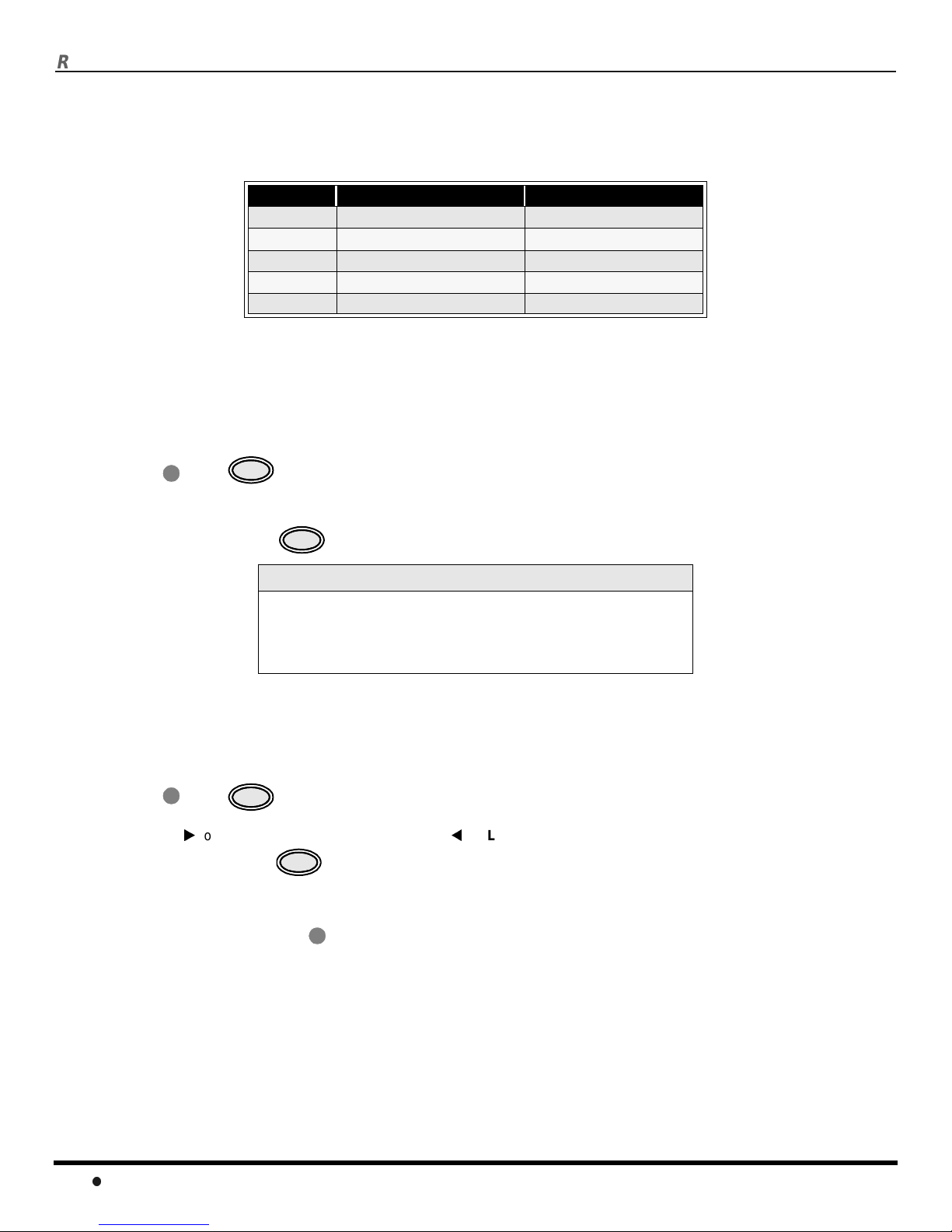
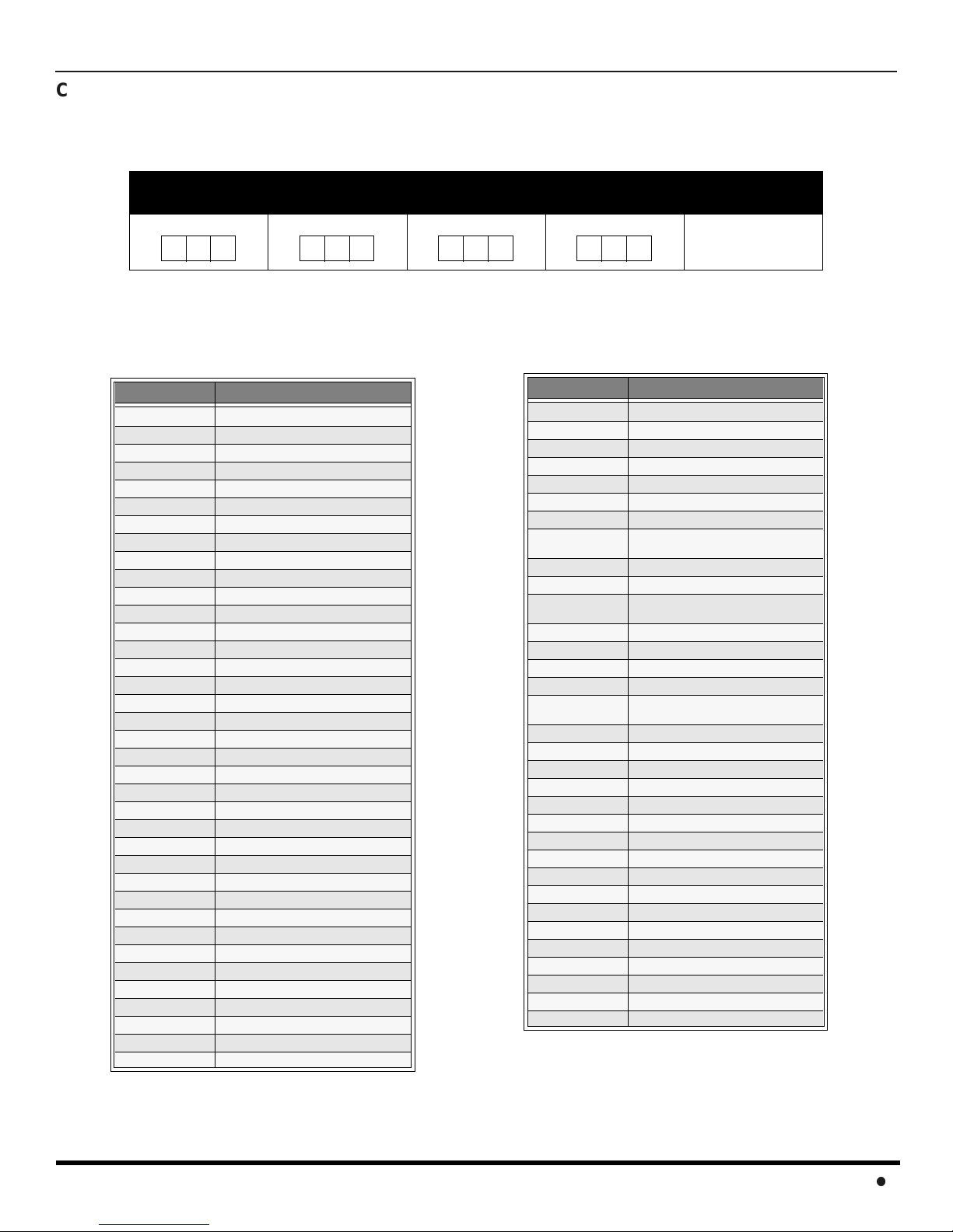
Component Codes
The Universal Remote Control is capable of operating many component brands after entering a code. Some components
may not operate because the codes are not available due to limited memory. The Universal Remote Control does not
control all features found in each model.
Write the code numbers from tables in this space. This will serve as a reference if you need
to program your Remote Control.
VCR DBS CABLE DVD
Codes For VCR
Brand Code
Admiral
Aiwa 332
Akai 314, 315, 316, 329
Audio Dynamic 311,339
Bell & Howell 305,313
Broksonic 320, 326
Canon 323, 325
CCE 343
Citizen 306
Craig 305, 306, 329
Curtis Mathes 324, 345
Daewoo 301, 324, 343
DBX 310, 311, 339
Dimensia 345
Emerson 303, 319, 320, 325, 326, 343
Fisher 305, 307, 308, 309, 313
Funai 320, 326, 334
GE 324,333, 345
Goldstar 306
Gradiente 334
Hitachi 300, 323, 345
Instant Replay 323, 324
Jensen 339
JVC 310, 311, 334,339
Kenwood 306, 310, 311, 339
LXI 300, 305, 306,307, 308, 309
Magnavox 323, 324, 331
Marantz 310, 311, 339
Marta 306
Memorex 309, 324
MGA 338, 340, 341, 347,348
Minolta 300, 345
Mitsubishi 338, 340, 341, 347, 348
Multitech 304,347
NEC 310,311, 334, 339
Olympic 323, 324
Optimus 306, 321, 328, 335
335
Brand Code
Orion 320, 326
Panasonic 321,322, 323, 324
J.C. Penney 300,305, 310, 311,324, 339, 345
Pentax 300,311, 345
Philco 320, 323, 324, 326, 331, 343
Philips 323, 324, 331
Pioneer 323
Proscan
Quasar 321, 322, 323, 324
RadioShack 305, 309, 324, 333, 336, 340
RCA
Realistic 305, 309, 324, 336, 340
Samsung 302, 304, 333
Sansui 320, 326, 339, 352
Sanyo 305,309, 313
Scott
Sears 300, 305, 306, 307, 308
Sharp 335, 336
Shintom 317
Signature 2000 335
Singer 337
Sony 328, 329, 330
Sylvania 331, 324, 331
Tashiro 306
Tatung 310, 311,339
Teac 310, 311, 339
Technics 321, 322, 323, 324
Teknika 324
Toshiba 301, 346
Vector Research 311
Wards 306, 309, 335, 336, 344
Yamaha 305,310, 311, 339
Zenith 306,344
300, 301, 302, 323, 324, 331, 333,
345, 346
300, 301,302, 323, 324, 331, 333,
345, 346
301, 302, 304, 309, 320, 326, 338,
340, 347, 348
13
R
EMOTECONTROLOPERATION
Component Codes (contd.)
Codes for C ab le Box
Brand Code
ABC 224
Archer 225, 232
Cableview 205, 232
Citizen 205, 222
Curtis 212, 213
Diamond 224, 225, 232
Eagle 229
Eastern 234
GC Brand 205,232
Gemini 222
General
Instrument/
Jerrold
Hamlin 212, 218, 240, 241, 242, 245
Hitachi 203, 224
Macom 203, 204, 205
Magnavox 233
Memorex 230
Movietime 205, 232
Oak 202, 237,239
Panasonic 209, 210, 214
Philips 206, 207, 228, 229, 230
Pioneer 201, 216
Pulsar 205, 232
211,219, 220, 221, 222, 223, 224,
225, 226, 227
Brand Code
Puser
RCA 215
Realistic 232
Regal 212, 218, 240, 241, 242, 245
Regency 234
Rembrandt 205,232,237
Samsung 205
Scientific Atlanta 211, 212, 213
Slmark 201,205
Sprucer 205, 210
Stargate 205, 232
Teleview 201, 205
Texscan 244
Tocom 235
Toshiba 204
Unika 225, 232
Universal 222, 232
Videoway 206
Viewstar 229, 230
Zenith 200, 217
Zenith / Drake
Satellite
232
200
Brand Code
Denon 100
Ferguson 101
JVC 109
Mitsubishi 105
Nordmende 101
Panasonic 100
Philips 103
Pioneer 102
RCA 101
Brand Code
Dish Network
(Echostar)
Echo Star 105
Express VU 105, 115
G.E. 106
G.I. (General
Instrument)
Gradiente 114
Hitachi 103, 111, 112
HNS (Hughes) 103
Magnavox 101, 102
105, 115, 116
108
Codes for DVD
Codes for DBS
Brand Code
Saba
Samsung 110
Sharp 108
Sony 104
Technics 100
Thomson 101
Toshiba 103
101
Yamaha 100
Zenith 107
Brand Code
Panasonic
Philips 101, 102
Primestar 108
Proscan 106, 109, 110, 113
RCA 106, 109, 110, 113
Sony 107
Star Choice 103, 108
Toshiba 100
Uniden 101, 102
104
14
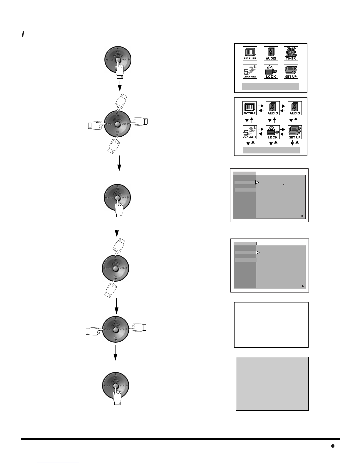
Icon Menu Navigation
Press to display the Icons.
Press to select desired icon.
I
CONMENUNAVIGATION
EXIT
EXIT
Press to display selected
Icon features.
Press to select feature.
Press
to adjust or activate feature.
PICTURE
VIDEO ADJ.
OTHER ADJ.
PICTURE
VIDEO ADJ.
OTHER ADJ.
PIC MODE VIVID
COLOR
TINT
BRIGHTNESS
PICTURE
SHARPNESS
NORMAL
PIC MODE VIVID
COLOR
TINT
BRIGHTNESS
PICTURE
SHARPNESS
NORMAL
-- -- -- I -- -- --
-- --
-- -- -- I -- -- --
-- -- -- -- ---- -- -- -- -- -- I
-- -- -- I -- -- --
-- --
-- --
-- --
-- -- -- -- ---- -- -- -- --
-- --
BRIGHTNESS 32 -- -- -- I -- -- --
-- I -- -- --
NO
--
I -- -- --
--
I -- -- --
--
I -- -- --
--
--
I -- -- --
NO
u
I
u
Press repeatedly to exit menus.
NORMAL PICTURE
15
M
AINMENUICONS
Main Menu Icons
EXIT
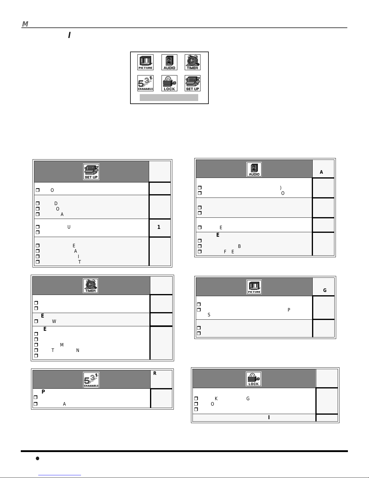
Icon Menus
These charts list all menus under each Icon and which pages to refer to for menus description.
IDIOMA/LANGUE
MODE - (ENGLISH, FRANÇAIS, ESPAÑOL)
PROG CHAN
MODE - (TV or CABLE)
AUTO PROGRAM
MANUAL PROGRAM
CC (CLOSED CAPTIONED)
CC ON M UTE
CC MODE
OTHER ADJ.
AUTO POWER ON
CHANNEL BANNER
GEOMAGNETIC CORR
TILTCORRECTION
CLOCK SET
TIME
DAY
SLEEP
HOW LONG?
TIMER
DAY
ON TIME
OFF TIME
ENTER CHANNEL
SET
REFER
TO
PAGE
17
17
18
18
19
REFER
TO
PAGE
20
20
20
AUDIO ADJ.
MODE (STEREO, SAP or MONO)
BASS, TREBLE, BALANCE OR NORMAL
OTHER ADJ.
AI SOUND
BBE
SURROUND
MODE
SPEAKERS
ON
OFF & VARIABLE AUDIO OUT
OFF & FIXED AUDIO OUT
VIDEO ADJ
PIC MODE
COLOR, TINT, BRIGHTNESS, PICTURE,
SHARPNESS or NORMAL
OTHER ADJ.
COLOR TEMP
VM
REFER
TO
PAGE
21
21
21
21
REFER
TO
PAGE
19
19
CAPTION
MANUAL CAPTION
INPUT LABEL
16
REFER
TO
PAGE
22
MODE
LOCK SET - (OFF,GAME, CHANNEL or A LL)
BLOCK PROGRAM
HOW LONG?
V-CHIP OPERATION 24
REFER
TO
PAGE
23
Icon Menu Operation
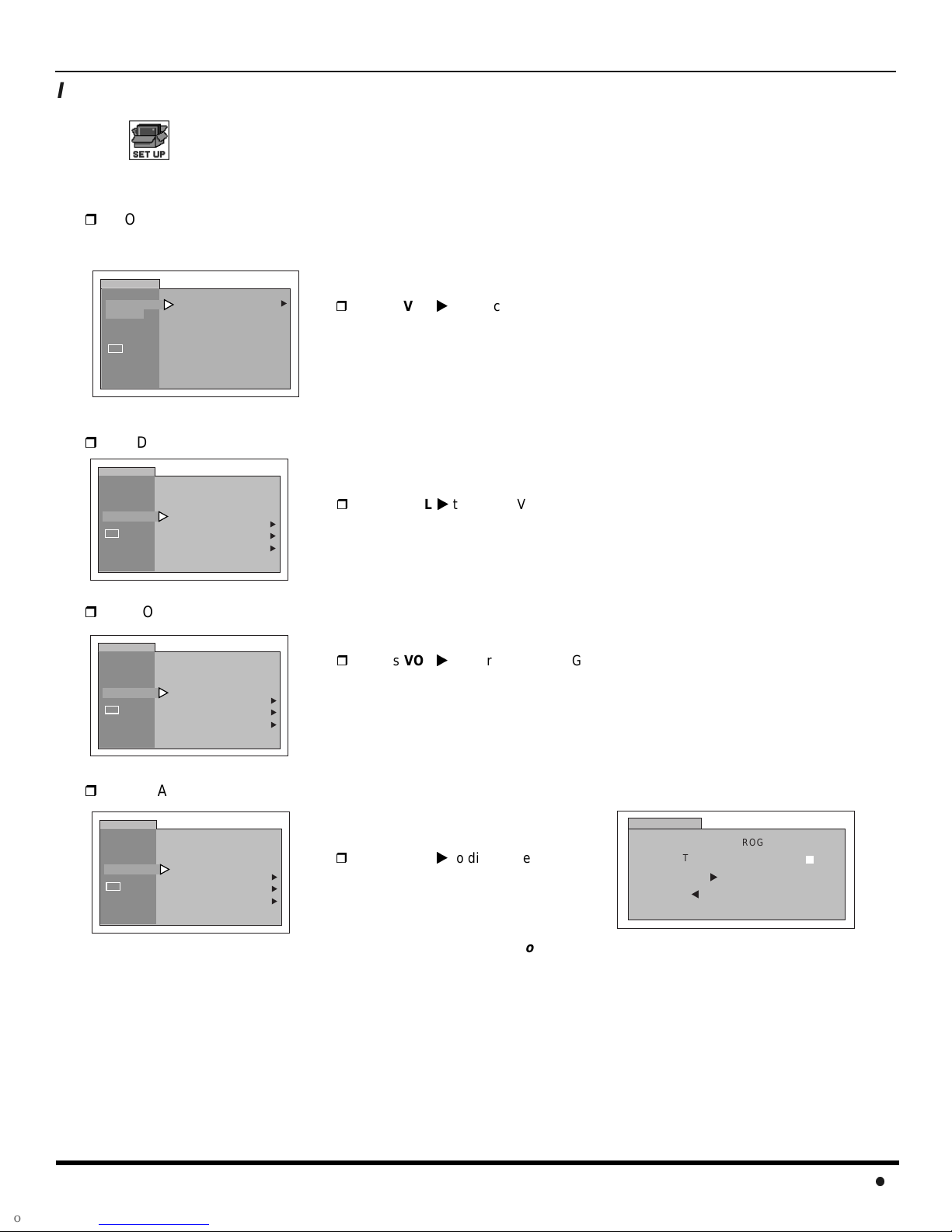
SET UP
Note: Refer to page 15 for Icon Menu Navigation procedures.
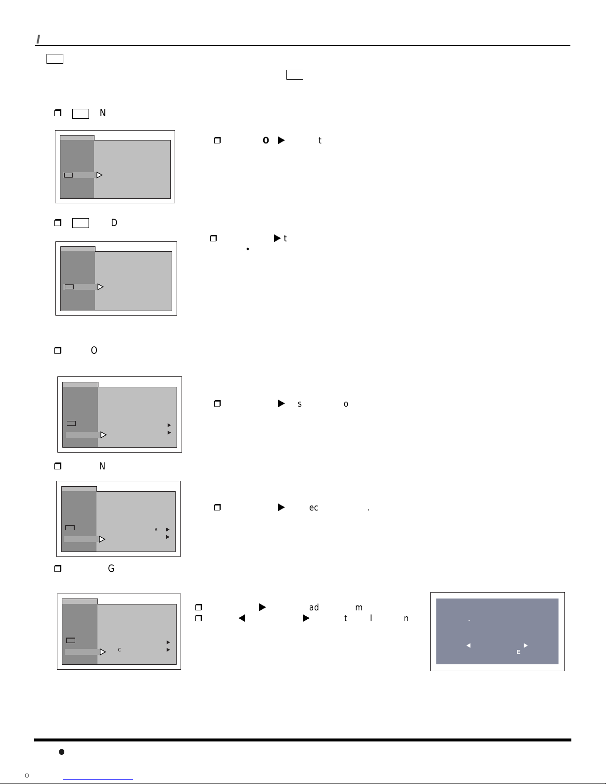
IDIOMA/LANGUE (Menu Languages)
MODE - In SET UP Menu, select IDIOMA/LANGUE to change menu language to ENGLISH, ESPAÑOL (Spanish)
or FRANÇAIS (French).
SETUP
IDIOMA/
LANGUE
PROG CHAN
CC
OTHER ADJ.
MODE ENGLISH
Prog Chan (Program Channels)
MODE - To select TV (antenna) or CABLE mode depending on the signal source.
SETUP
IDIOMA/
LANGUE
PROG CHAN
CC
OTHER ADJ.
MODE
AUTO PROGRAM
MANUAL PROGRAM
CABLE
u
u
u
u
Press VOLto select English, Spanish or French.
Press VOLto select TV or CABLE.
I
CONMENUOPERATION
AUTO PROGRAM - To automatically program all channels with a signal.
SETUP
IDIOMA/
LANGUE
PROG CHAN
CC
OTHER ADJ.
MANUAL PROGRAM - To manually add or delete channels.
SETUP
IDIOMA/
LANGUE
PROG CHAN
CC
OTHER ADJ.
MODE
AUTO PROGRAM
MANUAL PROGRAM
MODE
AUTO PROGRAM
MANUAL PROGRAM
CABLE
CABLE
u
u
u
u
u
u
Press VOLto start AUTO PROGRAM.
Press VOLto display next menu.
Note: Use Remote numeric keypad to enter channel
numbers.
SET UP
ENTER CHANNEL
t
MANUAL PROGRAM
u
TO ADD
TO DELETE
3
17
I
CONMENUOPERATION
CC
(Closed Captioning)
This television contains a built-in decoder that displays (Closed Captioned) text across the screen (white or colored
CC
letters on black background). It allows the viewer to read the dialogue of a television program or other information. The
program viewed must include Closed Captioning for the feature to work.
CC
ON MUTE - Activates the Closed Caption feature when the MUTE button on the remote control is pressed.
SETUP
IDIOMA/
LANGUE
PROG CHAN
CC
OTHER ADJ.
CC
SETUP
IDIOMA/
LANGUE
PROG CHAN
CC
OTHER ADJ.
CC ON MUTE NO
CC MODE OFF
MODE - Activates the onscreen Closed Caption feature by selecting one of the following modes:
CC ON MUTE NO
CC MODE OFF
Press VOLto select C1, C2, or NO.
Note: This feature only functions when the Closed Caption Mode is OFF. The recommended
setupforClosedCaptiononMuteis:
•CCONMUTE:C1
•CCMODE:OFF
Press VOLto select:
• OFF - When Closed Caption is not desired.
• C1 - For video related information to be displayed, up to 4 lines onscreen at
a time. (It does not block relevant parts of the picture). Text may be in any
language.
• C2 - Another Closed Captioning mode for video related information to be
displayed.
Nota: C1 mode is recommended for viewing Closed Captioning.
Other Adjustments
AUTO POWER ON - Select SET to power up the TV at the same time as the Cable box or other components or
select OFF.
SETUP
IDIOMA/
LANGUE
PROG CHAN
CC
OTHER ADJ.
AUTO POWER ON OFF
CHAN BANNER OFF
GEOMAGNETIC CORR
TILT CORRECTION
u
u
Press VOLto select OFF or SET.
CHANNEL BANNER - Select ON to display onscreen banner when changing channels.
SETUP
IDIOMA/
LANGUE
PROG CHAN
CC
OTHER ADJ.
GEOMAGNETIC CORR - This feature is used to adjust discoloration of the picture due to the earth’s magnetic field
AUTO POWER ON OFF
CHAN BANNER OFF
GEOMAGNETIC CORR
TILT CORRECTION
u
u
Press VOLto select OFF or ON.
Note: Press RECALL to display onscreen Channel Banner at any time.
in the area.
18
IDIOMA/
LANGUE
PROG CHAN
CC
OTHER ADJ.
SETUP
AUTO POWER ON OFF
CHAN BANNER OFF
GEOMAGNETIC CORR
TILT CORRECTION
Press VOLto display adjustment menu.
PressVOL or VOLto adjust discoloration in
picture.
u
u
GEOMAGNETIC CORRECTION
- - - - - - - - - - - - - - - - - -
0
l
t
TO ADJUST
PRESS ACTION TO EXIT
u
I
CONMENUOPERATION
Other Adjustments (contd.)
TILT CORRECTION - This feature is used to adjust the tilt of the picture due to earth’s magnetic field in the area.
SETUP
IDIOMA/
LANGUE
PROG CHAN
CC
OTHER ADJ.
AUTO POWER ON OFF
CHAN BANNER OFF
GEOMAGNETIC CORR
TILT CORRECTION
Press VOLto display adjustment menu.
PressVOL or VOLto adjust picture tilt.
u
u
PICTURE
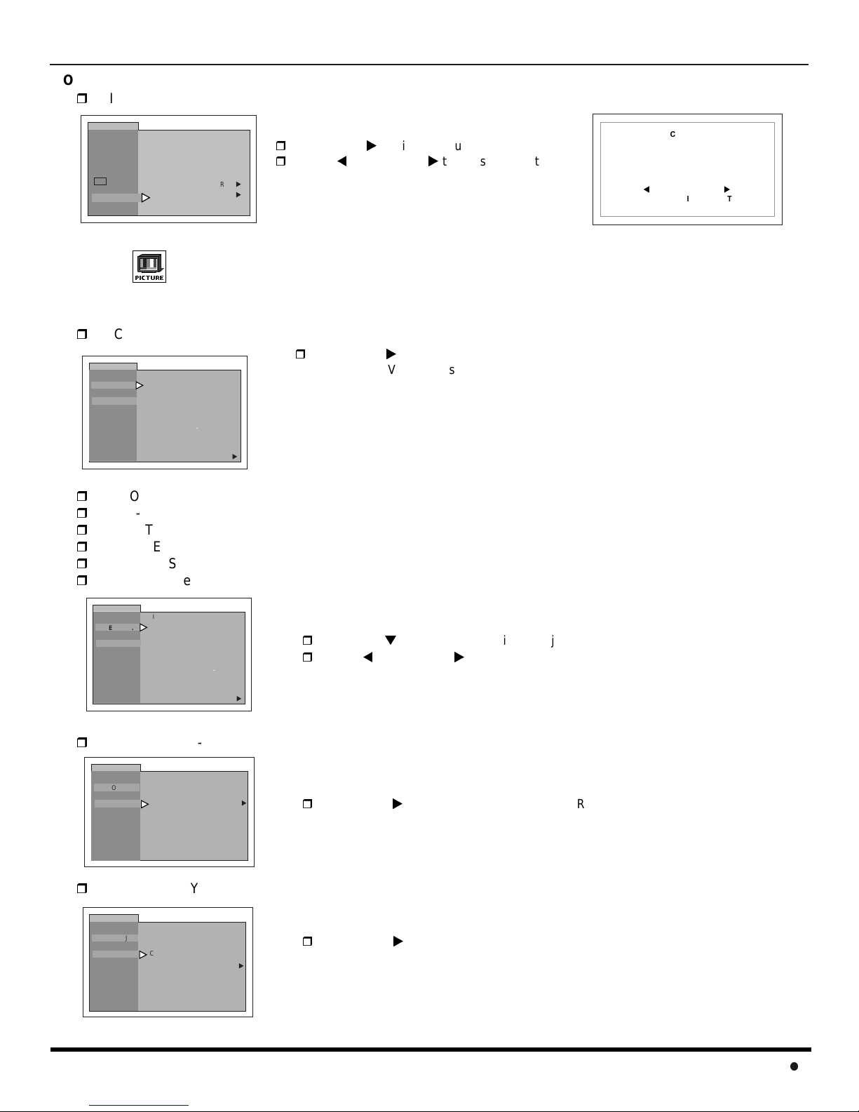
Note: Refer to page 15 for Icon Menu Navigation procedures.
Video Adj.
PIC MODE - Lets you choose one of three pre-set Picture Modes that best suit the program you are viewing.
PICTURE
VIDEO ADJ.
OTHER ADJ.
COLOR - Adjusts desired color intensity.
TINT - Adjusts natural flesh tones.
BRIGHTNESS - Adjusts dark areas of picture.
PICTURE - Adjusts white areas of picture.
SHARPNESS - Adjusts clarity of outline detail.
NORMAL - Reset all pictureadjustments to factory default settings.
PIC MODE VIVID
COLOR
TINT
BRIGHTNESS
PICTURE
SHARPNESS
NORMAL
-- -- -- I -- -- --
-- --
-- I -- -- --
-- -- -- I -- -- --
-- -- -- -- ---- -- -- -- -- -- I
-- -- -- I -- -- --
NO
u
Press VOLto select:
• VIVID - This is the default mode. It provides enhanced picture contrast and
sharpness for viewing in normal lighting.
• STANDARD - Recommended for normal viewing conditions with subdued
room lighting.
• CINEMA - Select mode for watching movies in a darkened room. It
provides a soft, film-like picture.
Note: Each mode has it’s own picture settings (Color, Tint, Brightness, Picture and Sharpness).
TILT CORRECTION
- - - - - - - - - - - - - - - - - -
0
l
t
TO ADJUST
PRESS ACTION TO EXIT
u
PICTURE
VIDEO ADJ.
OTHER ADJ.
PIC MODE VIVID
COLOR
TINT
BRIGHTNESS
PICTURE
SHARPNESS
NORMAL
-- --
--
--
-- --
-- --
--
-- -- -- -- ---- -- -- -- --
-- --
--
I -- -- - I -- -- --
I -- -- --
I -- -- --
NO
--
I
u
Press CHto select desired picture adjustment.
PressVOL or VOLto adjust.
Other Adj.
COLOR TEMP - To increase and decrease WARM (red) and COOL (blue) colors to suit personal preferences.
PICTURE
VIDEO ADJ.
OTHER ADJ.
VM (VELOCITY MODULATION) - Increases picture sharpness and provides crisp white to black transitions.
PICTURE
VIDEO ADJ.
OTHER ADJ.
COLOR TEMP NORMAL
VM OFF
COLOR TEMP NORMAL
VM OFF
u
u
Press VOLto select WARM, COOL or NORMAL.
Press VOLto select ON or OFF .
19
I
CONMENUOPERATION
TIMER
Note: Refer to page 15 for Icon Menu Navigation procedures.
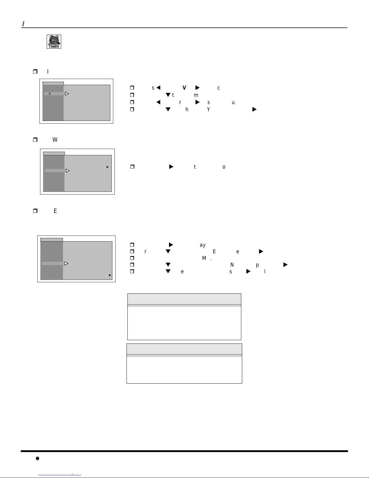
Clock Set
TIME and DAY - Set the time and the day of the week.
TIMER
CLOCK SET
SLEEP
TIMER
TIME - : - -
DAY _ _ _
AM
PressVOL or VOLto select hours AM or PM.
Press CHto select minutes position.
PressVOL or VOLto select minutes.
Press CHto highlight DAY, then press VOLto select day.
Sleep
HOW LONG? - Turn television off in 30, 60 or 90 minutes. Select NO to turn off timer.
TIMER
CLOCK SET
SLEEP
TIMER
HOW LONG?
NO
u
Press VOLto select 30, 60, 90 or NO.
Timer
TIMER - To turn the television on and off at selected times, on selected channels, and on selected days.
Note: TIME must be entered in CLOCK SET to operate the TIMER features.
TIMER
CLOCK SET
SLEEP
TIMER
DAY MON - FRI
ON TIME - - : - -
OFF TIME - - : - -
ENTER CHANNEL - - -
SET
NO
Press VOLto select day or days.
Press CHto select ON TIME, then press VOL.
Repeat for setting OFF TIME.
Press CHto select ENTER CHANNEL, then press VOLto select channel.
u
Press CHto select SET, then press VOLto select NO or SET.
20
Turn Off After 90 Minutes
The television automatically turns OFF after
90 minutes when turned ON by the TIMER.
If the OFF time is selected or if a key is
pressed, the automatic OFF after 90
minutes will be cancelled.
TIMER Activation
The TIMER is active when the television is
OFF or ON. The television will switch to the
selected channel at the selected time set in
the TIMER.
 Loading...