

Page 1

Panasonic
Color Television
Operating Instructions
PiliP
0
• WSVl
«■ »
• m C
\ V
№ \
N
CT-36SF24
For additional information about Panasonic products, visit our Internet site on the
Woild Wide Web at: http://www.panasonic.com
Read these Instructions completeTy before operating.
Contents subject to change without notice or obligation.
CopyrtgM I99r Oy MatousTaU Eleclne Corporaiiuii
ol Amertca. AH oghta rosefvwl Unoutionzed
copying and distrtKibon ia a vniabon of law.
W SPATIALIZER
m 3-0 STEREO
Printed in US.A
TOe2AACi»3
Page 2
Safety Instructions
WARNING
RISK OF ELECTRIC SHOCK
DO NOT OPEN
WARNING: To reduce the risk of electric shock do not remove cover or back. No
user-serviceable parts inside. Refer servicing to qualified service personnel.
A
The lightning flash with
arrow-head within a triangle
is intended to tell the user
that parts inside the product
are a risk of electric shock to
persons.
A
The exclamation point within
a triangle is intended to tell the
user that important operating
and servicing instnjctions are
in the papers with the
appliance.
Note To CATV System Installer: This reminder is provided to call the CATV system installer’s attention to Article
820-40 of the NEC that provides guidelines for proper grounding and, in particular, specifies that the cable ground shall be
connected to the grounding system of the building, as close to the point of cable entry as practical.
Safety Instructions For Television Receivers
1. Read and apply the operating instructions provided with your television receiver.
2. Read all of the instructions given here and retain them for later use.
3. Unplug this television receiver from the wall outlet before cleaning. Do not use liquid or aerosol cleaners. Use a damp
cloth for cleaning.
4. Do not use attachments not recommended by the television receiver manufacturer as they may cause hazards.
5. Do not use this television receiver near water. For example: Avoid placing it near a bathtub, washbowl, kitchen sink, or
laundry tub, in a wet basement, or near a swimming pool, etc.
6. Do not place this television receiver on an unstable cart, stand or table. The television receiver may fall, causing serious
injury to a child or adult, and serious damage to the appliance. Use only with a cart or stand recommended by the
manufacturer, or sold with the television receiver. Wall or shelf mounting should follow the manufacturer’s instructions,
and should use a mounting kit approved by the manufacturer.
6A. An appliance and cart combination should be moved with care. Quick stops, excessive force, and
uneven surfaces may cause the appliance and cart combination to overturn.
7. Slots and openings in the cabinet and the back or bottom are provided for ventilation, and to insure
reliable operation of the television receiver and to protect it from overheating. These openings must not be blocked or
covered. The openings should never be blocked by placing the television receiver on a bed, sofa, rug or other similar
surface. This television receiver should never be placed near or over a radiator or heat register. This television receiver
should not be placed in a built-in installation such as a bookcase unless proper ventilation is provided.
8. Operate only from the type of power source indicated on the marking label. If you are not sure of the type of power
supplied to your home consult your television dealer or local power company. For television receivers designed to
operate from battery power, refer to the operating instructions.
9. This television receiver is equipped with a polarized alternating^urrent line plug (a plug having one blade wider than the
other). This plug will fit into the power outlet only one way. This is a safety feature. If you are unable to insert the plug
fully into the outlet, try reversing the plug. If
the plug should still fail to fit, contact your
electrician to replace your obsolete outlet. Do
not defeat the safety purpose of the polarized
plug.
10. Do not allow anything to rest on the power
cord. Do not locate this television receiver
where the cord will be abused by persons
walking on it.
11. Follow all warnings and instructions marked
on the television receiver.
12. Do not overload wall outlets and extension
cords as this can result in fire or electric
shock.
13. Never push objects of any kind into this
television receiver through cabinet slots as
they may touch dangerous voltage points or
short out parts that could result in a fire or
electric shock. Never spill liquid of any kind on
the television receiver.
-2-
Page 3

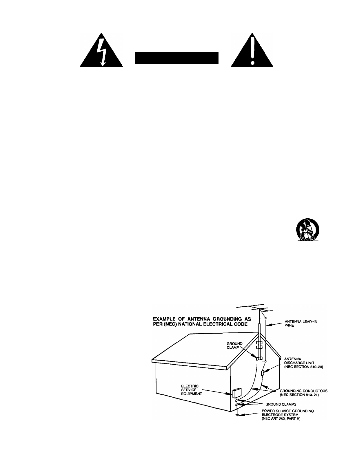
14. If an outside antenna is connected to the television equipment, be sure the antenna system is grounded so as to provide
some protection against voltage surges and built up static charges. In the U.S. Section 810 of the National Electrical
Code and in Canada Part 1 of the Canadian Electrical Code provides information with respect to proper grounding of the
mast and supporting structure, grounding of the lead-in wire to an antenna discharge unit, size of grounding conductors,
location of antenna-discharge unit, connection to grounding electrodes, and requirements forthe grounding electrode.
See Figure.
15. For added protection for this television receiver during a lightning storm, or when it is left unattended and unused for long
periods of time, unplug it from the wall outlet and disconnect the antenna. This will prevent damage to the receiver due to
lightning and power-line surges.
16. An outside antenna system should not be located in the vicinity of overhead power lines or other electric light or power
circuits, or where it can fall into such power lines or circuits. When installing an outside antenna system extreme care
should be taken to keep from touching such power lines or circuits as contact with them might be fatal.
17. Unplug this television receiver from the wall outlet, and refer servicing to qualified service personnel under the following
conditions:
When the power cord or plug is damaged or frayed.
a.
If liquid has been spilled into the television receiver.
b.
If the television receiver has been exposed to rain or water.
c.
d.
If the television receiver does not operate normally by following the operating instructions. Adjust only those controls
that are covered by the operating instructions as improper adjustment of other controls may result in damage and will
often require extensive work by a qualified technician to restore the television receiver to normal operation.
If the television receiver has been dropped or the cabinet has been damaged.
e.
When the television receiver exhibits a distinct change in performance - this indicates a need for service.
f.
18. Do not attempt to service this television receiver yourself as opening or removing covers may expose you to dangerous
voltage or other hazards. Refer all servicing to qualified service personnel.
19. When replacement parts are required, be sure the service technician has used replacement parts specified by the
manufacturer that have the same characteristics as the original part. Unauthorized substitutions may result in fire,
electric shock, or other hazards.
20. Upon completion of any service or repairs to this television receiver, ask the service technician to perform routine safety
checks to determine that the television is in safe operating condition.
21. WARNING: To prevent fire or shock hazard, do not expose this appliance to rain or moisture.
22. CAUTION: TO PREVENT ELECTRIC SHOCK DO NOT USE THIS (POLARIZED) PLUG WITH A RECEPTACLE OR
OTHER OUTLET UNLESS THE BLADES CAN BE FULLY INSERTED TO PREVENT BLADE EXPOSURE.
NOTE: This equipment is designed to operate in the U.S.A., Canada and other countries where the broadcasting system and
AC house current is exactly the same as in the U.S.A. and Canada.
Important Information Regarding Use of Video Games, Computers, Teletext or Other Fixed Image Displays.
The extended use of fixed image program material can cause a permanent “shadow image” on the picture tube. This
background image is viewable on normal programs in the form of a stationary fixed image. This type of irreversible picture
tube deterioration can be limited by observing the following steps:
A. Reduce the brightness/contrast setting to a minimum viewing level.
B. Do not display the fixed image for extended periods of time.
C. Turn the power off when not in actual use.
NOTE: The marking or retained image on the picture tube resulting from fixed image use is not an operating defect and as
such is not covered by Warranty. This product is not designed to display fixed image patterns for extended periods of
time.
Power Source:
Channel Capability:
Video Input Jacks (3):
Audio Input Jacks (3):
To Audio AMP Jacks:
S-VHS Input Jack (2):
Stereo Sound
Specifications
120V AC, 60Hz
181 channels (See chart)
VHF 2-13, UHF14-69, Cable 125 channels
1V p-p, 75 ohm, phono jack type
500mV rms, 47K ohm
0-2.0V rms 4.7K ohm
S-Video (Y-C) Connector
Channel Capability Chart
CHANNELS
VHF
UHF
CABLE (Mid-Band)
CABLE (Super Band)
CABLE (Hyper Band)
CABLE (Ultra Band)
TOTAL CHANNELS
12
56
15
14
28
56
181
Spatializer Surround Sound
Closed Caption Display
Picture In Picture:
1 Tuner
Specifications are subject to change without notice or obligation.
-3-
Page 4

Congratulations on Your New Purchase
Your new video component features an all solid state chassis which is designed to give you many years of enjoyment. It
was thoroughly tested and adjusted at the factory for best performance.
In order for you to take full advantage of your new video component, please read and follow the installation and operating
instructions supplied with this product.
Customer’s Record
The model and serial number of this product may be found on its back cover. You should note the model and serial number
in the space provided and retain this book as a permanent record of your purchase to aid in identification in the event of
theft or loss.
Model Number;
Serial Number:
You may register your new television set on the Internet at: http://www,prodreg.com/panasonic
-4-
Page 5

Table of Contents
Safety Instructions................................................................ 2
Specifications
Introduction ............................................................................ 4
Installation
Television Location
Optional External Equipment Connections ......................... 6
AC Power Supply Cord
Remote Control Battery Installation
Antenna/Cable Connections
Other Video Equipment...................................................... 7
Care & Cleaning................................................................. 7
Optional Equipment Connection and Operation
Stereo Connection (To Audio AMP) .................................. 8
Video/Audio Connection
S-Video Connection .......................................................... 9
PIP External Video & Antenna Connections
PIP External Video & Antenna Connections
Using Cable Box ...........................................................10
Location of Controls for Television
Quick Reference Control Operation
Basic Remote Control Functions for
Remote Control
Remote Control Quick Reference Functional
Key Chart
Special Functions
Recall Button..................................................................... 15
R-Tune (Rapid Tune) Button............................................. 15
Multi Button
PIP (Picture in Picture) Button
PIP Swap Button ............................................................. 16
PIP Size Button................................................................ 16
PIP Freeze Button
PIP Move Button.............................................................. 16
Main Menu (Trilingual Animated Icons)
Language Menu............................................................ 17
Picture Adjustments...........................................................17
Picture Norm................................................................. 17
Color, Tint, Brightness, Picture and
Color Temp (Temperature)
........................................................................
............................................................
......................................................
..................................
..............................................
...................................................
......................................
.................................
............................................................
......................................................................
.......................................................................
.........................................
..........................................................
Sharpness Adjustments
...........................................
...........................................
6
6
6
7
8
.........................
11
11
12
13
15
16
16
17
18
Auto Color
3
Video NR............................................................. 18
Audio Adjustments
..........................................................
18
Audio Norm......................................................... 19
Bass, Treble and Balance
Mode - Stereo/SAP/Mono
.................................
.................................
19
19
Speaker [TV]....................................................... 20
Spatializer............................................................20
Al Sound
.............................................................
20
Input Select
Main (Picture) Input Selection
PIP (Picture in Picture) Input Selection
.........................
..........
21
21
Timer Features
Sleep Timer.........................................................21
Program Timer....................................................21
Lockout Features
Lockout Mode
.....................................................
22
Unlock .................................................................24
9
Favorite Channel Features
Channel Scan
......................................................
24
Favorite Channel Select.....................................25
Channel Caption Features
Preset Caption
...................................................
25
Manual Caption ..................................................26
Set Up Features
Clock (Auto)
Clock (Manual)
.......................................................
....................................................
26
28
Set Day ................................................................28
Mode (TV or Cable).............................................28
Auto Programming
.............................................
29
Manual Programming ........................................29
Auto Power On....................................................30
Closed Caption with Mute Button
Closed Caption Mode
.........................................
....................
30
30
Programming the Illuminated Remote Control
Using Access Codes ....
....................................31
VCR Infrared Codes Index .......................................32
Cable Box and CD Players
Infrared Codes Index .........................................33
Cassette Deck, Receivers, and Amplifiers
Infrared Codes Index .........................................34
Laser Disc, DSS, and DVD
Infrared Codes Index .........................................35
Troubleshooting Chart .............................................36
-5-
Page 6
Installation
Television Location
This television is intended to be used with an optional stand or entertainment center. Consult your dealer for available options.
Locate for comfortable viewing. Avoid placing where sunlight or other bright light (including reflections) will fall on the screen.
Use of some tyF>es of fluorescent lighting may reduce remote control transmitter range.
Adequate ventilation is essential to prevent internal component failure. Keep away from areas of excessive heat or moisture.
To insure optimum color purity do not position equipment containing magnets (motors, fans, external speakers, etc.) nearby.
Optional External Equipment Connections
The Video/Audio connections between components can be made with shielded video and audio cables. For best
performance, video cables should be of 75 ohm type coaxial shielded cables. Cables are available from your dealer or
electronic supply house.
Before you purchase any cables, check out the type of output and input connectors your various components require.
Also determine the length of cable you will need.
AC Power Supply Cord
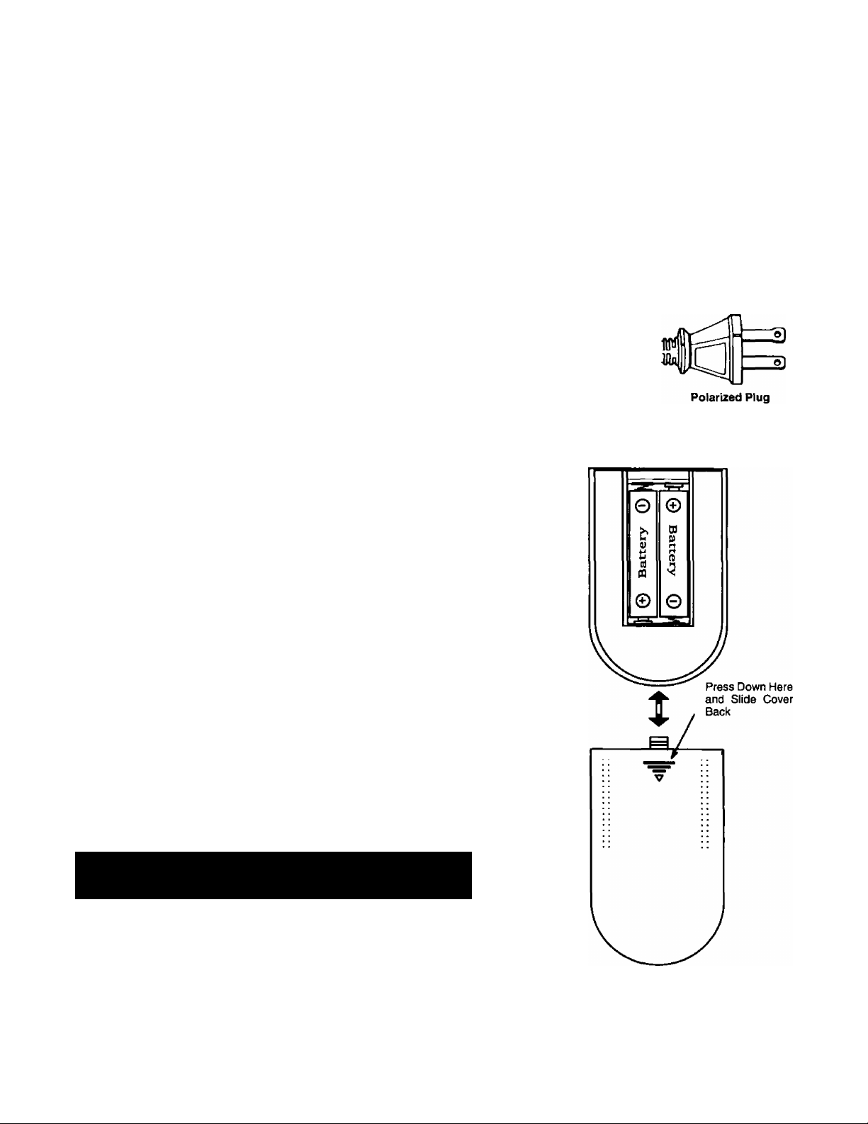
CAUTION: TO PREVENT ELECTRIC SHOCK, MATCH WIDE BLADE OF PLUG TO WIDE
SLOT OF AC OUTLET AND FULLY INSERT. DO NOT USE THIS (POLARIZED) PLUG
WITH A RECEPTACLE OR OTHER OUTLET UNLESS THE BLADES CAN BE FULLY
INSERTED TO PREVENT BLADE EXPOSURE.
Remote Control Battery Installation
Batteries: Use two “AA” batteries.
1. Remove the battery compartment cover on back of
the remote.
Install the batteries in the battery compartment.
2.
(Polarity (+) or (-) must be correct.)
Reattach the battery cover.
3.
Helpfui Hints:
For frequent Remote Control users, replace old batteries with
Alkaline batteries for longer life.
Precaution on Battery Use
Incorrect installation can cause battery leakage and corrosion
that will damage the Remote Control.
Observe the Following Precautions:
1. Batteries must be replaced as a pair.
2. Do not combine a used battery with a new one.
3. Do not mix battery types (Example: “Zinc Carbon” with “Alkaline”).
4. Do not attempt to charge, short-circuit, disassemble, heat or burn used
batteries.
5. Battery replacement is necessary when Remote Control reacts
sporadically or stops operating the television.
Note: In order to maximize the life of the batteries, the
lighted buttons on the Remote Control can be turned OFF
and ON by pressing R-TUNE and RECALL simultaneously.
Hefpfut Hints:
Whenever you remove the batteries to replace
them, you may need to reset the Remote Control
Infrared Codes. We recommend that you initially
record the codes in the Infrared Remote Codes for
Specific Components section, prior to setting up the
remote.
_______________________
____________
-6-
Page 7
Installation (Cont)
Antenna/Cable Connections
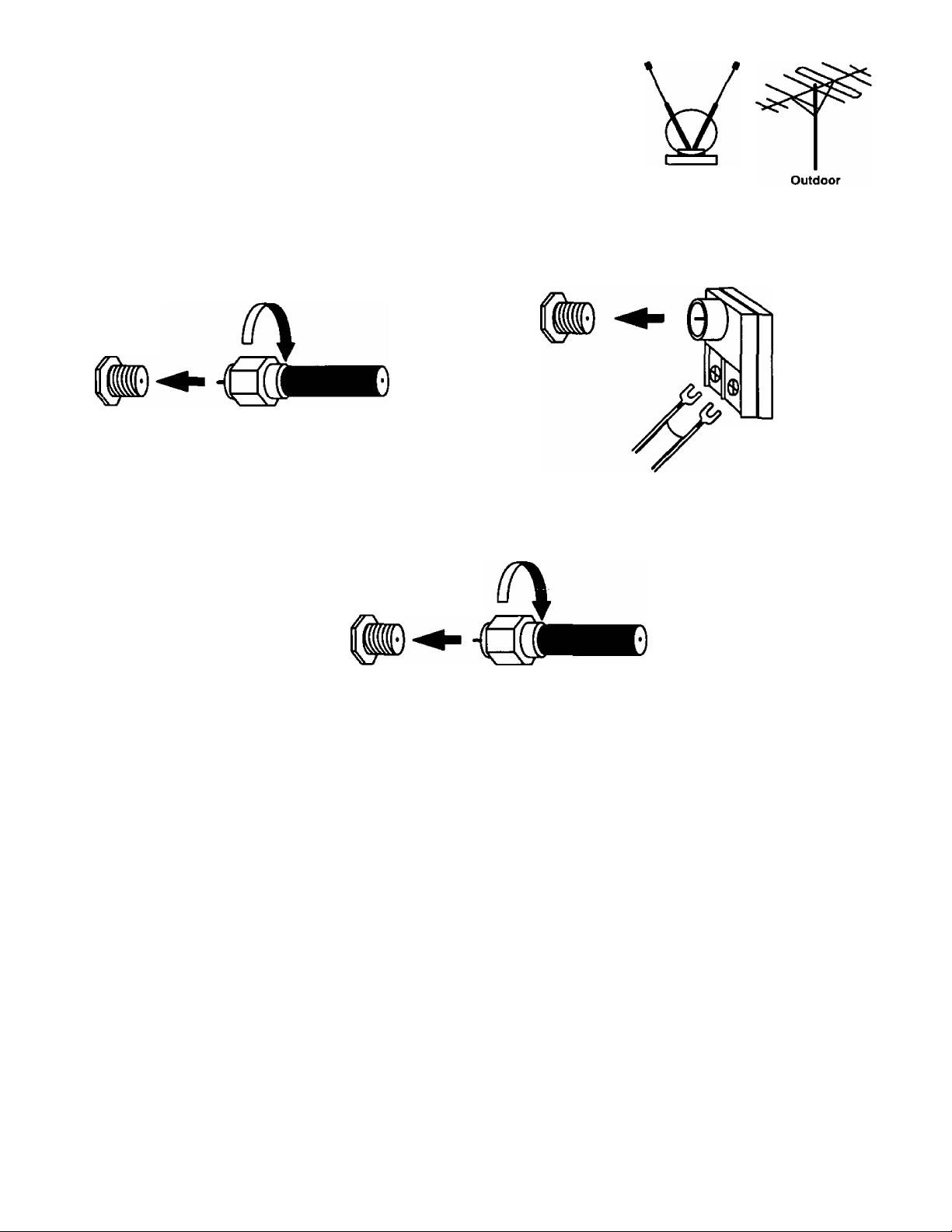
Antenna Connection - For proper reception of VHF/UHF channels, an external
antenna is required. For best reception, an outdoor antenna is recommended. In the
SETUP menu, set the MODE to TV. (Refer to Antenna Mode section.)
Indoor
Incoming Cable from Home Antenna
VHF/UHF
75 Ohm
VHF/UHF
on Back of Set
on Back of Set 300 Ohm
or
Cable Connection - For reception of cable channels, connect the cable supplied by your local cable company. In the
SETUP menu, set the MODE to CABLE. (Refer to Antenna Mode section.)
Typical VHF/UHF Antenna
300 to 75 ohm Matching
Transformer (Not Included)
Incoming Cable from Cable Company
75 Ohm
VHF/UHF
on Back of Set
NOTE: Certain cable systems offset some channels to reduce interference, or have premium (scrambled) channels. A
cable converter box is required for proper reception. Check with your local Cable company for compatibility
requirements.
Other Video Equipment
VCRs, Video Disc Players, Computers, TV games, and DSS equipment can also be connected to the antenna input
connection.
Care and Cleaning
Picture Tube (Turn television off)
Use a mild soap solution or window cleaner and a clean cloth. DO NOT USE ABRASIVE CLEANERS. Avoid excessive
moisture and wipe dry.
Plastic Cabinet
Wipe the cabinet with a soft cloth dampened with water or a mild detergent solution and wipe dry with a soft clean cloth.
Avoid excessive moisture. Do not use benzene, thinners or other petroleum based cleaners.
Wood Cabinet
When dusting or polishing the cabinet, use a clean soft cloth and stroke straight with the grain. An occasional coat of
furniture polish will help preserve the finish. Do not use benzene, thinners or other petroleum based cleaners. Do not
place objects made of plastic or rubber directly on top of the cabinet. A chemical reaction could result causing permanent
marring of the finish.
Remote Control Transmitter
Use a soft cloth slightly moistened with a mild detergent and then wipe dry with a soft clean cloth. Avoid excessive
moisture. Do not use benzene, thinners or other petroleum based cleaners.
-7-
Page 8
Optional Equipment Connection and Operation
To Audio AMP Connection (Stereo)
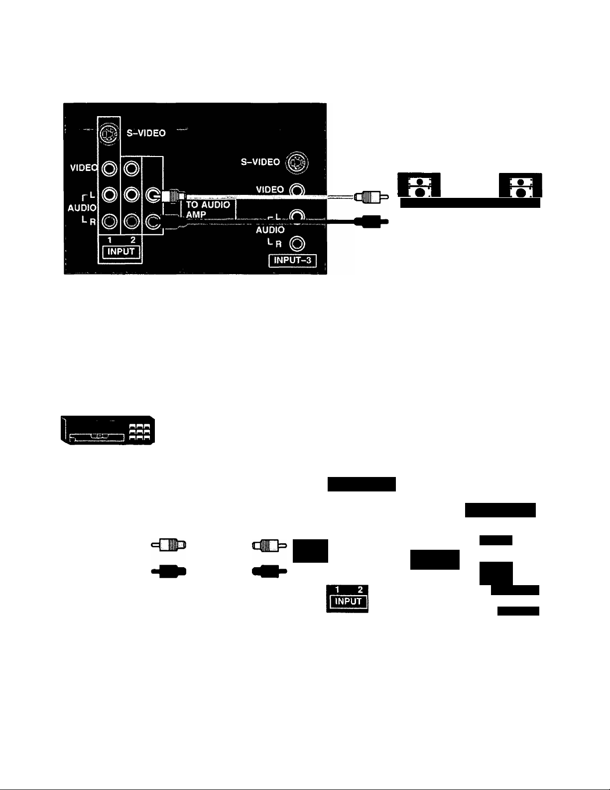
Connect to an external audio amp auxiliary input for monitoring sound through a stereo system.
TERMINALS ON BACK OF TELEVISION
‘TO AUDIO AMP” terminals
cannot be used directly with
external speakers.
(Connecting
Cables Not
Supplied)
Adjustment - When an audio amp is connected to ‘TO AUDIO AMP” terminals:
1. Select TV SPEAKERS “ON ” Mode. (Refer to the Audio Menu TV Speakers section.)
Set voiume of audio amp to near minimum.
Adjust volume of TV to desired iistening level.
Adjust volume of audio amp to match the ievel of TV.
Select TV SPEAKERS “OFF&VAO” Mode. (Refer to the Audio Menu TV Speakers section.)
Audio bass, trebie, balance, volume and mute can now be controlled by the TV Remote Control.
NOTE: When Selecting TV SPEAKERS “OFF&FAO” Mode, the TV sound output is always at a constant level and cannot
be changed (Refer to the Audio Menu TV Speakers section).
AudioA^ideo Input Connection I S-Video connection is optional
and overrides the standard Video
connection when connected.
OPTIONAL EQUIPMENT
S*ViDEO
VlC^OOUT
AU^'OUT
' n
TERMINALS ON BACK
OF EQUIPMENT
(Not Supplied)
p L
AUDIO
TERMINALS ON BACK OF TELEVISION
ti S-VIDEO
S-VIDEO
VIDEO
TO AUDIO
AMP
AUDIO
INPUT-3
Operation
1. Connect optional equipment as shown to INPUT 1,2 or 3 terminals. (Additional INPUT 3 terminals are located on the
front of the television behind the door. Make sure that the INPUT 3 FRONT/REAR switch located behind the front
door is set properly.) If S-Video is to be used, connect S-Video (YC) connector to S-Video terminal and connect
audio cables to L & R Audio INPUT 1 or INPUT-3 terminals.
2. Select the desired Video mode by pressing the TVA/IDEO button.
3. Operate optional equipment (VCR-VDP) as instructed in Optional Equipment manual.
NOTE:
• You must select the proper VIDEO Input Mode where the equipment is connected.
• Connection of optional S-VIDEO jack automatically disconnects the Normal Video Input 1 or 3 jacks.
-8-
Page 9
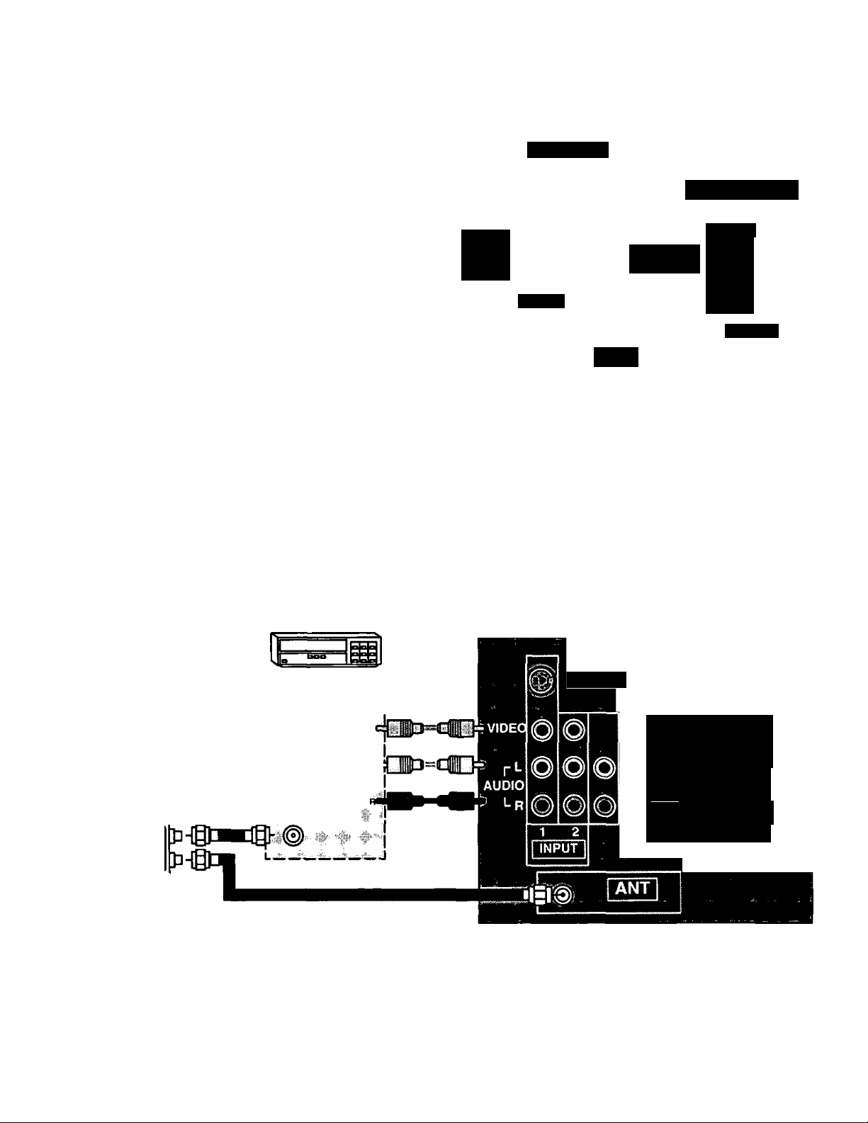
S-Video Connection
VCR or VIDEO DISC
i
’ S-VIDEO {[(I .O-
'vireo OUT
; AUDIO <XJT
, R if
TERMINALS ON
BACK OF VCR
I
VCR S-V1DEO (YC)
CONNECTOR OPTIONAL
p L
AUDIO
Lr
TERMINALS ON BACK OF TELEVISION
m S-VIDEO
TO AUDIO
AMP
1 2
ANT
Operation
1. Connect S-Video (YC) connector to S-Video Terminals INPUT 1 or INPUT-3 (rear of television).
Connect the L and R Audio Input jacks. Use the terminal jacks located directly below the S-Video jack used.
When using the INPUT-3 jack, verify that the switch located behind the front door is set to REAR (unpressed).
Select Video! mode by pressing the TVA/IDEO button (or refer to the Input Select Menu).
Operate optional equipment (VCR-VDP) as instructed in Optional Equipment manual.
NOTE:
• You must select the proper VIDEO Input Mode where the equipment is connected.
• Plugging into the optional S-VIDEO jack automatically disconnects the Normal Video Input 1 or Input 3 jacks.
S-VIDEO
VIDEO
p L
AUDIO
i-R
INPUT-
j
Picture in Picture Externai Video and Antenna Connection
This television has the “PICTURE IN PICTURE” feature. For the proper operation of this feature a second video source
is required (such as a VCR). We recommend that you make your antenna and External Video connection as shown below
when a second video source is available.
VCR or VIDEO
DISC PLAYER
TERMINALS ON BACK OF VCR
Incoming Cable
From Antenna Or
Cable TV System
To VCR
Ant Input
■ua-i
TSr
Signal Splitter
(not Included)
4 #
: MJKoouT
ANT INPUT
-Si-
To ANT Terminal
TERMINALS ON BACK OF TELEVISION
S-VIDEO
S-VIDEO i
VIDEO
TO ÀUDIO
AMP
AUDIO
Lr
$^pfuPHinBr
The PIP will operate using AudioA/ideo input terminals 1,2 or 3 (additional input 3 is located on front of television).
Use the TVA/IDEO button (when the PIP frame is displayed) to select proper mode.
The PIP feature will operate using S-Video input terminal 1.
-9-
Page 10
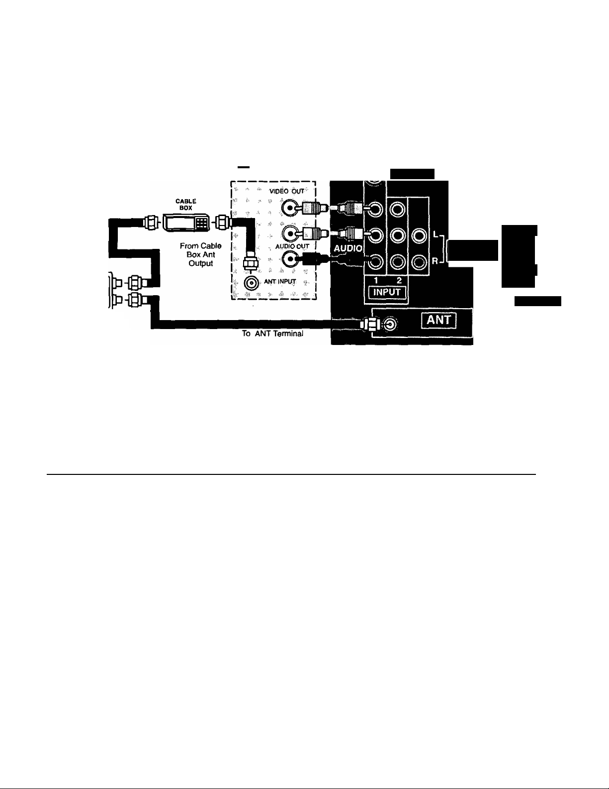
Picture in Picture and External Video and Antenna Connection
(Optional Connection, Using Cable Box)
This television has the “PICTURE IN PICTURE” feature. For the proper operation of this feature a second video source
is required (such as a VCR). We recommend that you make your antenna and External Video connection as shown below
when a second video source is available.
TERMINALS ON BACK OF TELEVISION
VCR or VIDEO
DISC PLAYER
To Cable
Box Ant
Input
i
TERMINALS ON BACK OF VCR
S-VIDEO
Incoming Cable
From Antenna Or
Cable TV System
I ^
TO AUDIO
AMP
VIDEO
rt
AUDIO
Lr
INPUT-3
^Tsr
Signal Splitter
(not Included)
NOTE:
• Set your television to channel 3 or channel 4, as specified by your Cable Box manual.
• You must select the proper VIDEO Input Mode where the equipment is connected.
• Plugging into the optional S-VIDEO jack automatically disconnects the Normal Video Input 1 or Input 3 jacks.
• Select VIDEO for the PIP frame and ANT for the main picture, or vice versa.
• Use the Cable Box for channel selection.
*Helpful Hints: ■ t < t g .1. » » .■ t
The PIP will operate using Audio/Video input terminals 1, 2 or 3 (additional input 3 is located on front of television).
Use the TVA/IDEO button (when the PIP frame is displayed) to select proper mode.
The PI P feature will operate using S-Video input terminal 1.
-10-
Page 11
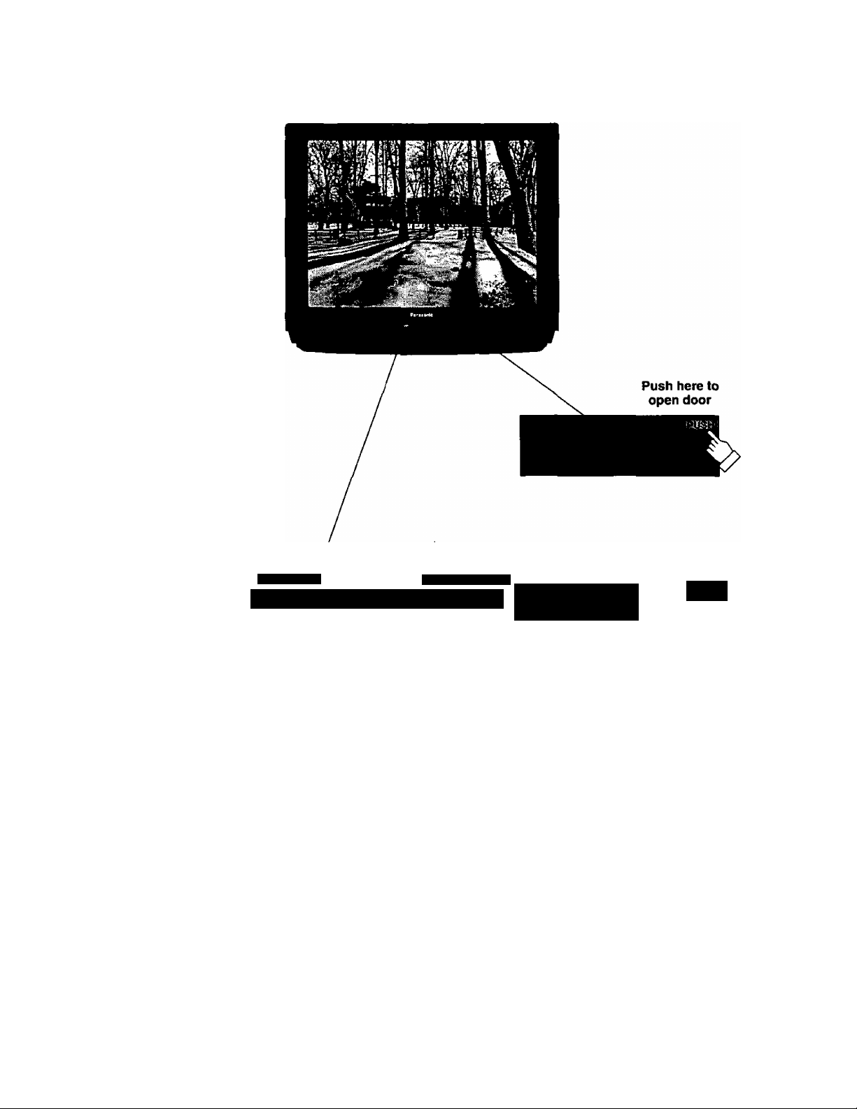
Location of Controls
Front Control Panel
Remote Control
Sensor
4 VOLUME ^
CIZ! ÍIZ3 ÍZD CZD CZ] cz:
(i) (s) (s) 0© ©
ACTION TV/VIDEO
f to
I; smr ^
;i*r
Front Video 3 Jacks Located Behind Door
O ;h
Quick Reference Control Operation
Power Button - Press to turn television ON or OFF.
Volume Buttons - Press to adjust Sound Level, Audio and Video Menus and to select operating features when
menus are displayed.
Channel Buttons - Press to select programmed channels or to highlight desired features when menus are
displayed.
Action Button - Press to display Main Menu and access or exit On Screen feature and Adjustment Menus.
TV/Video Button - Press to select TV or one of three Video Inputs, for the Main Picture or the PIP frame (when PIP
frame is displayed).
Front/Rear INPUTS Selection Switch - Use to set the source of INPUT 3 (INPUT Scan receive signal from either
the front or the rear jacks)
-11 -
Page 12
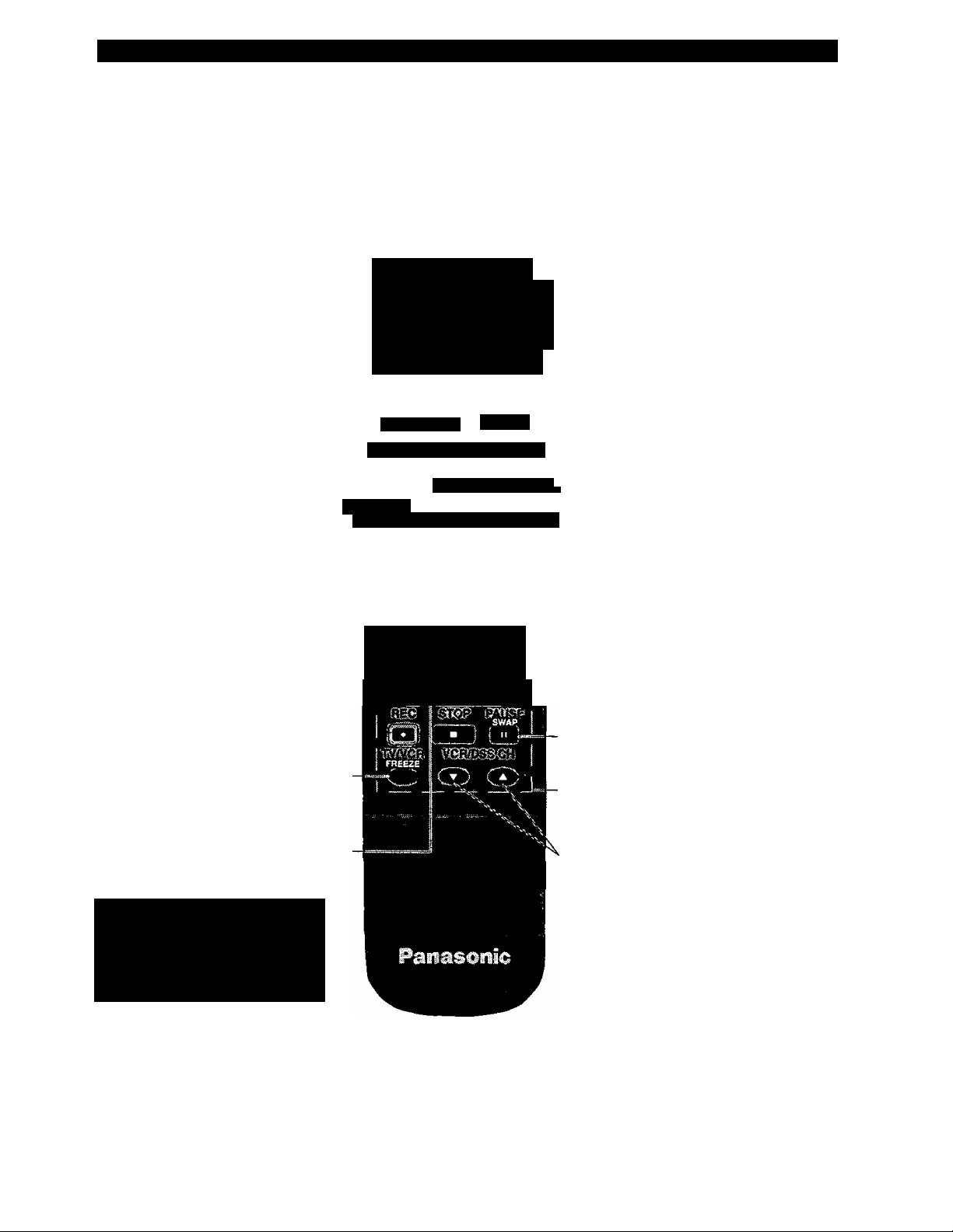
Location of Controls for the Illuminated Home Theater Remote Control
Basic Remote Control Functions
For Television Operation
The following is an overview of the Remote Control unit for television
of^ation. Ensure the TV mode is selected by initially pressing
Please refer to the indicated pages for additional information.
Multi Button
Programmable to operate up to six
Remote Function buttons simulta
neously.
Power Button
Press to turn the TV ON or OFF.
Mode Selection Buttons
Select the operation mode for the
remote control.
Volume Buttons
Press to adjust TV sound level. Use
writh Channel buttons to navigate in’
menus.
Action Button
Press to display Main Menu and
enter or exit On Screen feature and
Adjustment Menus.
R-Tune (Rapid Tune) Button
Press to switch to the previously
viewed channel.
PIP Move Button
Press to position PIP frame to any
comer of the Main Picture (when PIP
frame is displayed).
PIP Freeze Button
Press to stop action in the Main Picture
or PIP frame (when the PIP frame is
displayed).
PIP Size Button
Press to selecit size of PIP frame
(when the PIP frame is displayed).
r0- Q
Numeric Keypad (“0 through 9'’ Buttons)
Press desired channel number to randomly
access any channel.
I O 0 0 I
TV/Video Button
Press to select TV or one of various Video
_ Inputs, for the Main Picture or the PIP
frame (when the PIP frame is displayed).
Mute Button
Press to mute sound. A second press
resumes sound.
Channel Buttons
■Press to select channels. Use with
Volume buttons to navigate in menus.
Recall Button
Press to display Time, status of Sleep
Timer, Channel, Video McxJe, Channel
Caption (Station Identifier) and Audio
Mode.
PIP (Picture In Picture) Button
Press to display the PIP frame, press again
to remove PIP frame.
PIP Swap Button
Press to interchange PIP frame with Main
Picture (when the PIP frame is displayed).
VCR Function Buttons
Programmable to operate many brands of
VCRs.
VCR/DSS Channel Buttons
Select VCR or DSS Up/Down channels.
POWERTli
....
.. .s . ■ ..
rr^'
MOVE SIZE RP
...
r:...i.GS>l
•^1
To prolong the life of the
batteries, the illumination of the
keys can be toggled ON and
OFF by pressing the R-TUNE
and the RECALL buttons
simultaneously.
Helpful Hints:
If the selected component does not respond to the remote control,
ensure that the proper mode is selected. First, press the Mode
Selection Button that corresponds to that component. For example,
after first pressing the TV Mode Button, the remote will remain In the
TV mode for the following commands. If a different mode button is
pressed white operating the tetevision, the TV mode button must be
pressed again to enable the TV mode control.
-12-
Home Theater Remote Control
EUR511060A
NOTE:
For additional information on the Remote
Control, please refer to the Remote Control
Quick Reference Functional Key Chart.
Page 13
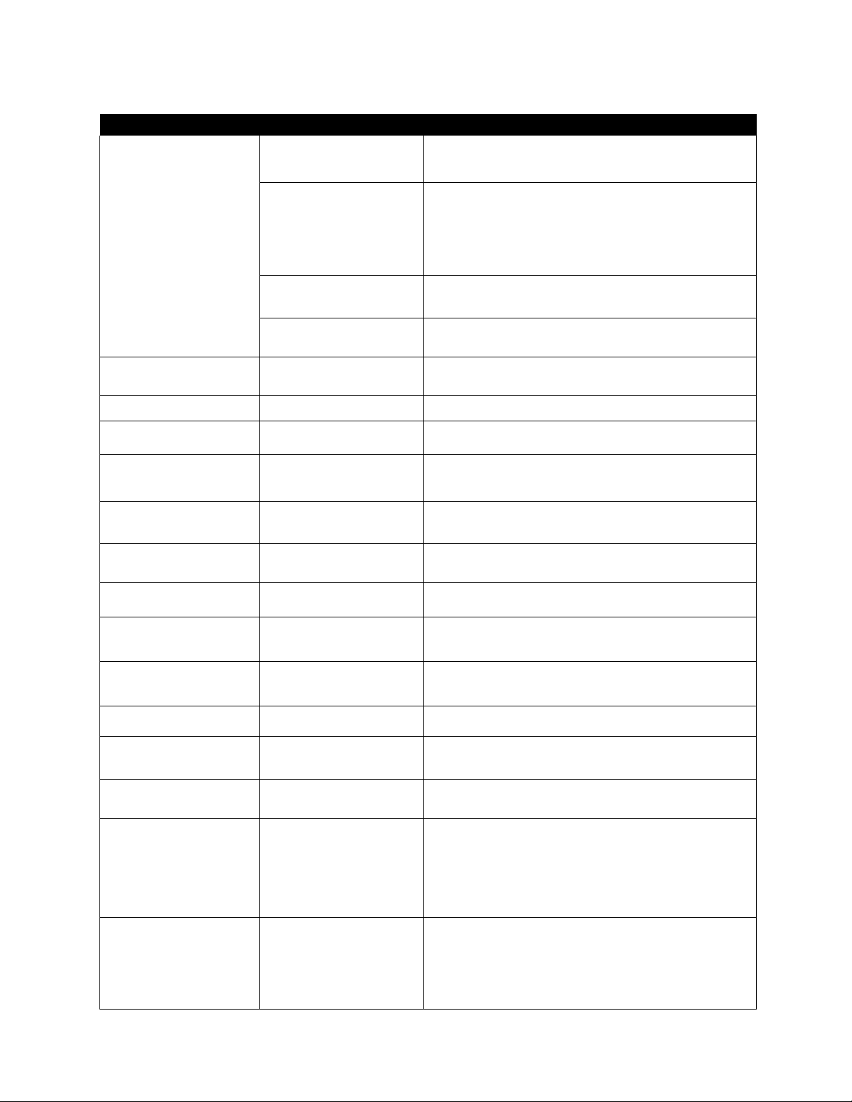
Remote Control
Quick Reference Functional Key Chart
KEY
© ® (D
® ® ®
® ® ®
®
(j^OWE^
Cmute])
MODE
TV
VCR, VCR 2
CABLE, DSS
RECEIVER/AMPLIFIER
Selects Channel
Selects Channel
Selects Channel
® Selects Tuner
® Selects CD Player
® Selects Tape Cassette Player
FUNCTION
© VCR 1 / VIDEO 1
® VCR 2/VIDEO 2
® VCR 3/VIDEOS
CD PLAYER Selects Track Number
LD PLAYER
ALL COMPONENTS
TV
ALL COMPONENTS
TV, DSS, VCR, VCR 2 LDP
CABLE
RECEIVER/AMPLIFIER
TV TV Mode Selection for Remote Control
Selects Track Number
Programmable Button That Can Operate Up To Six (6)
Remote Functions At Once
Selects the TV Input Mode
Turns On and Off Selected Components
Mutes TV Audio
Mutes Audio
Mutes Audio
%
%
C0^
A
CABLE
DSS (DIGITAL SATELUTE
SYSTEM)
VCR
RECEIVER/AMPLIFIER
COMPACT DISC CD Mode Selection for Remote Control
CASSETTE PLAYER,
VCR 2, DVD
LASER DISC PLAYER LD Mode Selection for Remote Control
TV
CABLE
DSS
LDP
CD
RECEIVER/AMPLIFIER
DVD
TV
CABLE
DSS
RECEIVER/AMPLIFIER
VCR, VCR 2 1
LDP 1
Cable Mode Selection for Remote Control
DSS Mode Selection for Remote Control
VCR Mode Selection for Remote Control
Receiver/Amplifier Mode Selection for Remote Control
AUX Mode Selection for Remote Control
Enables User to Operate a Tape Cassette Player,
Digital Video Disc or Second VCR
Channel Up/Down, Menu Navigation
Channel Up/Down
DSS Guides and Menu Navigation
Skip
FF, REW
Preset or Tuning Frequency
Skip FWD/Sktp REW
Volume Up/Oown, Menu Navigation
Volume Uptown
DSS Guides and Menu Navigation, Also Switches Between
Normal Audio and SAP
Volume Up/Down
TV Volume Up/Down
TV Volume Up/Down
-13-
Page 14
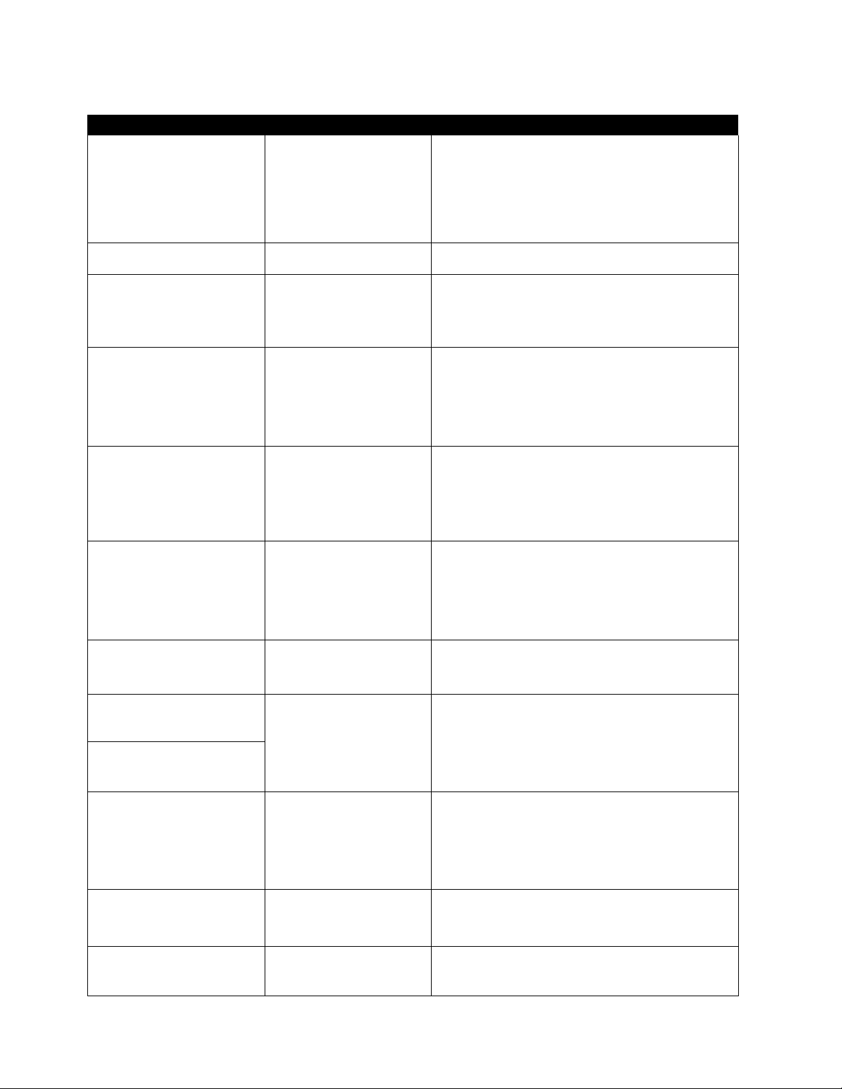
Remote Control
Quick Reference Functional Key Chart (Cont.)
KEY MODE FUNCTION
LDP Side A/8
TV
Q-TUNp
if*™])
REW
MOVE
PLAY
SIZE
CF~)
FF
PIP VCR, VCR 2 Fast Fonward
Cgs>
REC
f(^j]
STOP
Co:
PAUSE
TV/VCR
FREEZE
O
CABLE Switches Between Two (2) Channels
VCR, VCR 2 Switches Between Two (2) Channels
DSS Switches Between Two (2) Channels
RECEIVER/AMPUFIER
CD Selects Next Disc
TAPE CASSETTE PLAYER Selects Tape Cassette Player A or B
TV
DSS Acts as Menu Button for DSS
TV
DSS
VCR, VCR 2
LDP
TV
DSS DSS Guide
VCR, VCR 2 Rewind
LDP Rewind
TAPE
CD
DVD Rewind
TV
DSS Enter/Select
VCR, VCR 2
LDP Play
TAPE Play (in Normal Direction)
CD Play
DVD Play
TV
DSS Exit/Clear
LDP
TAPE
CD
DVD
DSS One Touch Record in DSS Mode
VCR, VCR 2 Record
TAPE Record
CABLE VCR Record
DVD Stop
VCR, VCR 2
LDP
TAPE Stop
CD Stop
CABLE VCR Stop
DVD
TV
VCR, VCR 2 Pause
LDP
TAPE Pause
CD Pause
CABLE
TV
VCR, VCR 2
DSS Selects TV/DSS Mode
CABLE
Switches Between Two (2) Channels
Switches between AM and FM
Activates TV Menus
Displays Channel, Sleep Time,Channel Caption, Time,
and Audio Mode
Displays Current DSS Settings
Displays Current VCR Settings
Displays Current LDP Settings
PIP Move
Rewind
Selects Previous Track
PIP Size
Play
PIPOn/Off
Fast Fonward
Fast Fonward
Selects Next Track
Fast Forward
Stop
Stop
Pause
PIP Swap
Pause
VCR Pause
PIP Freeze
Selects TVA/CR Mode
Selects TVA/CR Mode
VCR/DSS CH
CS> CE>
VCR, VCR 2 Channel Uptown
DSS Channel Up/Down
-14-
Page 15
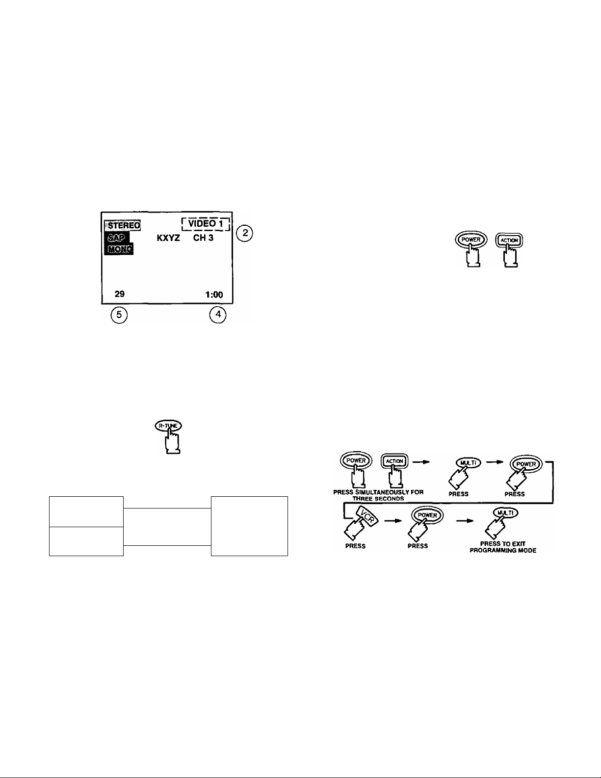
Special Functions
Recall Button
Press the RECALL button to review:
(T) Audio Mode status
@ CH number or Video Input selected
@ Channel Caption (Station Identifier)
(4) Clock time
@ Sleep Timer status
© ®
R-Tune Button
Pressing the R-TUNE (RAPID TUNE) button toggles to
the previously tuned program.
Multi Button
The MULTI button can be programmed to operate up
to six (6) remote function buttons at the same time.
For Example: TV Power/On, VCR Power/On, and
Cable Box Power/On (selected brands) can be operated
at the same time with one press of the MULTI button.
(The VCR Mode button should be programmed
before starting procedure).
Procedure
1. Program the Rennote for the selected device Infrared
access code. Confirm that the Remote Control is
compatible with the device.
2.
Face the Remote Control transmitter away from all
equipment remote sensors.
Press and hold the Remote Control POWER button,
3.
then press and hold the ACTION button down
simultaneously for three seconds. (All previous
commands are erased.)
PRESS SIMULTANEOUSLY FOR
THREE SECONDS
4.
After three seconds, release the POWER and
ACTION buttons.
5.
Press the MULTI button. (Waiting more than 30
seconds without pressing another button will exit the
programming mode.)
Press a maximum of six (6) function buttons on the
6.
Remote Control.
Each button pressed is equal to one function. If six
(6) Remote button functions are entered, all will
register in the MULTI button memory in the
sequence entered. When finished, press the MULTI
button to exit the programming mode.
The following is an example flow chart of remote
functions that can be programmed into the MULTI
button.
PROGRAM
CURRENTLY VIEWED
Press Button
Press Button Again
PROGRAM
PREVIOUSLY VIEWED
Helpful Hints:
Press the TV Mode Selection button to operate TV
Remote functions, if necessary.
You can now turn the TV and VCR ON/OFF at the
same time with one press of the MULTI button.
To delete entered functions - Press and hold the
Remote Control POWER button, then press and
hold the ACTION button down at the same time for
three seconds. You can now enter from one to six
different Remote functions.
NOTE: You can also program the MULTI button to
perform most individual Remote Control button
functions. Buttons which continuously perform a
function as long as pressed (Volume Up/Down,
Channel Up/Down, etc.) cannot be programmed;
only those buttons which perform a function
when initially pressed (Power On/Off, Mute,
Direct Channel Entry, etc.) can be programmed.
-15-
Page 16
Special Functions
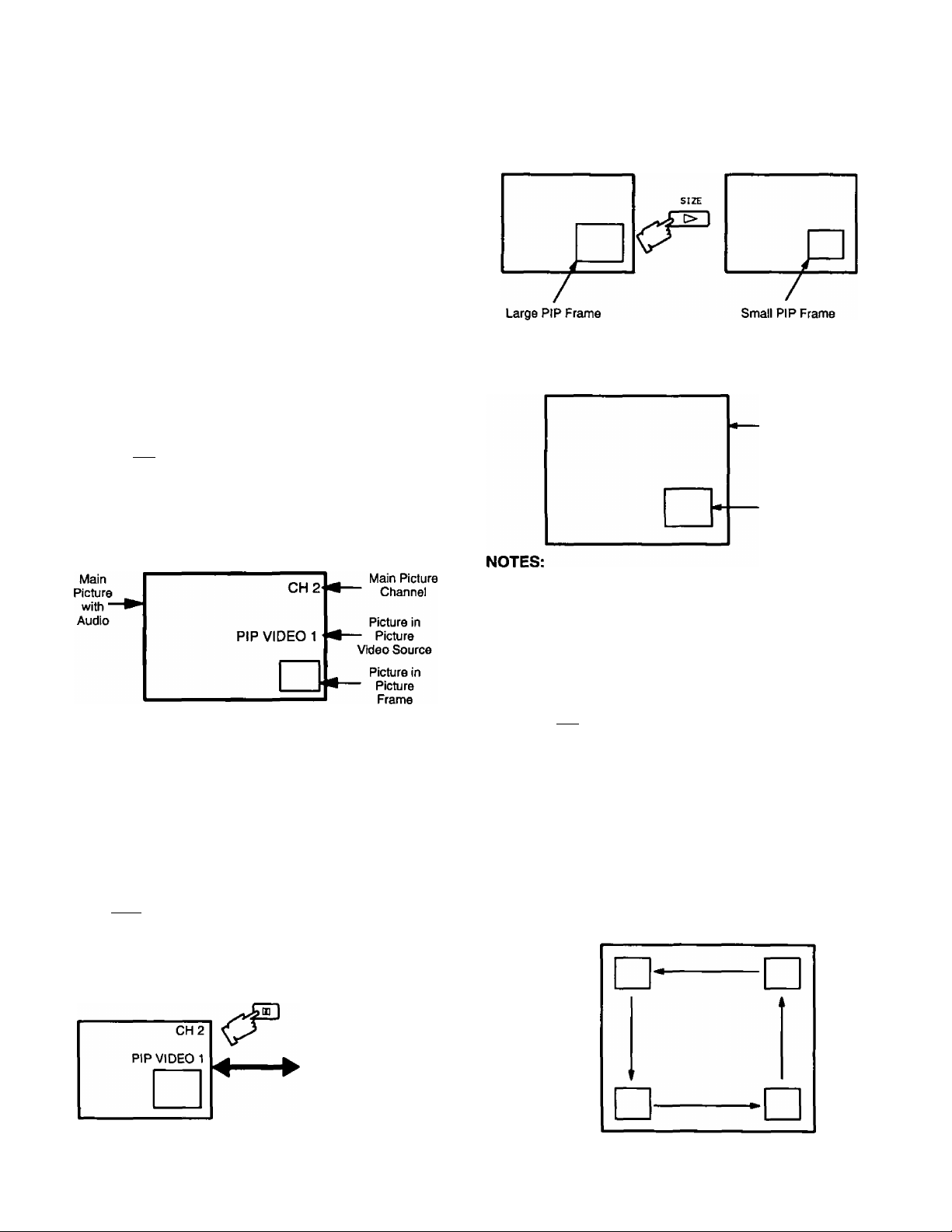
PIP (Picture in Picture) Button
This feature allows viewing one channel program while
monitoring another. The monitored source (PIP) must be
a different video source (such as a VCR) when connected
to the input jacks.
• S-Video connection will also operate the PIP feature
(refer to OPTIONAL S-VIDEO VHS CONNECTION
section)
• When the Main Picture is in Video mode with no signal,
the PIP will not operate properly.
PIP Operation
1. Turn VCR ON and select a desired channel.
2. Press
necessary.
PIP
Press (set must be ON). The PIP frame will
3.
appear at the position it was last displayed. The Main
Picture Video Source and PIP Video Source will
display on screen momentarily. Audio will be that of
Main Picture.
operate TV Remote functions, if
Size Button
SIZE
Press(when the PIP frame is displayed) to choose
either the large or small PIP frame.
Freeze Button
FREEZE
Press
o
to stop action in the PIP frame.
Main
Picture
Freeze
Frame
PIP
4. Press again to cancel PICTURE IN PICTURE
feature (if desired).
NOTE: For PIP Video source connection, refer to the
PIP EXTERNAL VIDEO AND ANTENNA
CONNECTIONS section.
Swap Button
SWAP
Press L“J (when the PIP frame is displayed) to
interchange what is being viewed on the Main Picture with
that of the PIP frame.
FREEZE
• PressingCiD whenthePIPframeisnotdisplayed, will
display a snapshot image of the main picture in the PIP
frame.
• Pressing
action in the PIPframe. Press the FREEZE button again
to continue action.
• Press to remove PIP frame.
o
PIP
FREEZE
when PIP frame is displayed, will stop
Move Button
The PIP frame may be placed at any corner of the Main
Picture by pressing the
the PIP frame is displayed).
NOTE: Each time is pressed (when the PIP frame
is displayed), the PIP frame will move
counterclockwise as illustrated.
MOVE
PIP MOVE button (when
MOVE
NOTE: Audio will be that of Main Picture.
VIDEO 1
PIP CH 2
-16-
Page 17
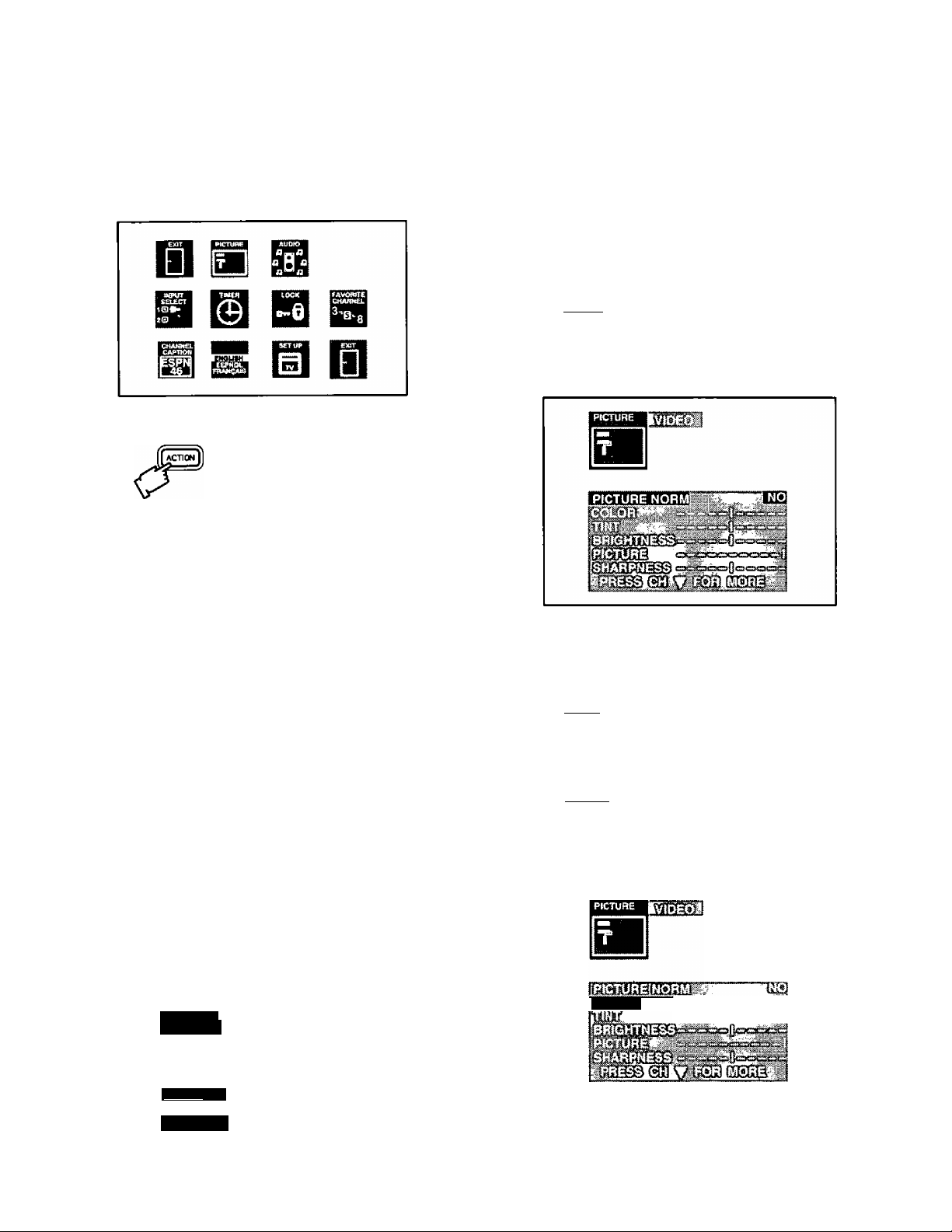
Main Menu
(Trilingual Animated Icons)
The MAIN MENU allows the user to configure the
television according to their preference. It will also set
up the television to operate with external components
connected to the terminal jacks.
NOTE: Only the selected icon (red) will be animated.
Display and Exit Menus
CH BUTTONS
Highlight Desired
A
Feature on Menus
VOL BUTTONS
Selects or Adjusts
Features on Menus
4. Press A or to select ENGLISH. ESPAÑOL or
FRANÇAIS for the Language Menu.
5. Press twice to exit menus.
Picture Adjustments
Picture Norm — Use to reset Color, Tint, Brightness,
Picture, and Sharpness adjustments to the factory preset
level.
1. Press [LssJJ.
2. Press A or ^ and/or ^ to highlight the Picture
Icon.
3. Press to display the Picture Adjustment Menu.
Located On Remote Control
Helpful Hint:
Some menu selections are available only under certain
conditions. For example, the Al SOUND in the AUDIO
menu is available only if the SPATIALIZER is set OFF.
When the SPATIALIZER is set ON, the Al SOUND is
not displayed.
Menu Language Selection
The MENU LANGUAGE is factory set to ENGLISH.
Follow the instructions to change it to SPANISH,
FRENCH, and back to ENGLISH.
1. Press
2. Press A or ^ and or ^ to highlight the
Language ENGLISH/ESPANOL/FRANQAIS Icon.
3. Press to display the Language select Menu.
ESPAÑOL
FRANÇAIS
4. Press A or W to highlight PICTURE NORM.
5. Press or ^ to select “SET” to normalize Color,
Tint, Brightness, Picture, and Sharpness.
6. Press ibssJ] twice to exit menus.
Color, Tint, Brightness, Picture, and Sharpness Adjustments
1. Press [LESiij).
2. Press or and or to highlight the Picture
Icon.
3. Press to display the Picture Adjustment Menu.
COLOR
n %
ENGLISH
mmim
4. Press A or to select the desired Picture
Adjustment (Color, Tint, Brightness, Picture, or
Sharpness).
-17-
Page 18
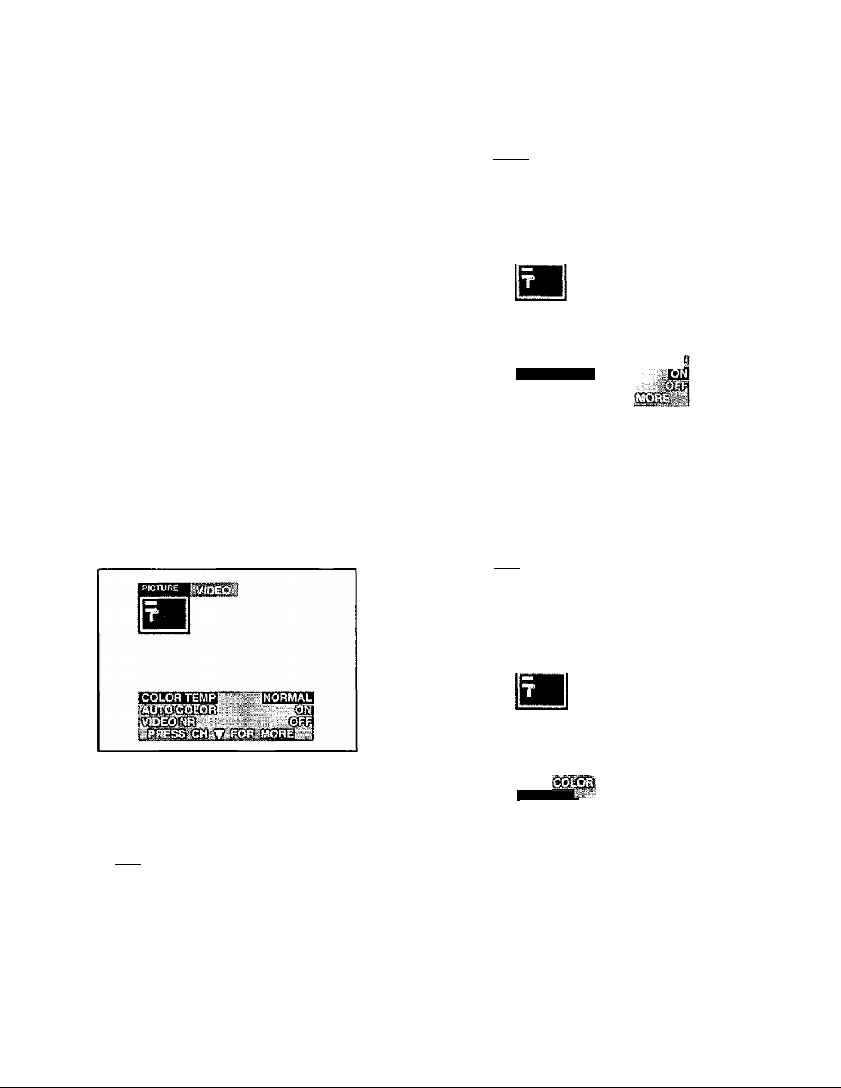
Picture Adjustments
Color, Tint, Brightness, etc. (Cont.)
5. Press or ^ to adjust your selection. (The
Selected Picture Adjustment will be displayed.)
6. Repeat steps 4 and 5 for the remaining Picture
Adjustments.
7. Press twice to exit menus.
Heipfu! Hints:
COLOR - Adjust for desired color intensity.
TINT - Adjust for natural flesh tones.
BRIGHTNESS - Adjust so dark areas of picture slightly
become black for a crisp detail.
PICTURE - Adjust the white areas of the picture as
desired.
SHARPNESS - Adjust for best clarity of outline detail.
Color Temp — To select one of three (3) options for
picture temperature.
1. Press
Auto Color — To automatically optimize color
adjustment to compensate for signal variations.
1. Press ILsigJ].
2. Pressi or Wand'€ or to highlight the Picture
Icon.
3. Press'
4. Pressi or W to highlight AUTO COLOR.
5. Press or ^ to select ON or OFF.
6. Press twice to exit menus.
to display the Picture Adjustment Menu.
mMMmm.....................mMm
AUTO COLOR
2. Press ^ or W and or ^ to highlight the Picture
Icon.
3. Press
4. Press ^ or to highlight COLOR TEMP.
5. Press or ^ to select NORMAL, WARM, or COOL.
• NORMAL (no tint)
• WARM (reddish tint)
• COOL (bluish tint)
6. Press twice to exit menus.
to display the Picture Adjustment Menu.
Video NR (Noise Reduction) - To reduce video
noise (snow in picture) due to weak signal.
1. Press iteiJ}.
2. Press ^ or Wand‘s or to highlight the Picture
Icon.
3. Press (^3 to display the Picture Adjustment Menu.
VIDEO NR
4. Press ^ or W to highlight VIDEO NR (Noise
Reduction).
5. Press or ^ to select ON or OFF.
6. Press ^3 twice to exit menus.
-18-
Page 19
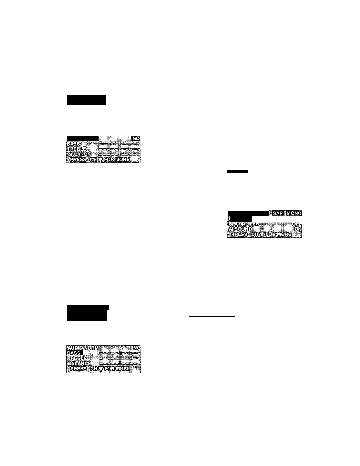
Audio Adjustments
Audio Norm — This feature is used to reset BASS,
TREBLE and BALANCE back to a factory preset level.
1. Press to display the Main Menu.
2. Press ^ or Wand'^ or ^ to highlight the Audio
Icon.
3. Press I
4. Press ^ or ^ to highlight AUDIO NORM.
5. Press or ^ to select “YES” to Normalize Bass,
Treble and Balance.
to display the Audio Adjustment Menu.
umi
AUDIO NORM
Helpful Hints:
BASS - To increase or decrease the Bass response.
TREBLE - To increase or decrease the Treble
response.
BALANCE - To emphasize the Right and Left
Speaker’s volume.
Mode - Stereo/SAP/Mono — When Audio
is broadcast in Stereo or SAP an ON Screen display will
appear on initial “Turn On” and “Channel Change”. The
available choices will be indicated in red.
1. Press to display the Main Menu.
2. Press ^ or W and or ^ to highlight the Audio
Icon.
3. Press the^3 to display the Audio Adjustment Menu.
Aumo
6. Press ^3 twice to exit Menus.
Bass, Treble & Balance — Before setting Bass
or Treble select the desired mode of Al Sound (ON or
OFF). Bass and Treble Adjustments may require
readjustment when changing between Al Sound ON or
OFF.
1. Press fesJJ to display the Main Menu.
2. Press A or W and or ^ to highlight the Audio
Icon.
3. Press I
to display the Audio Adjustment Menu.
AUDIO pOTii
n H «
MODE »STEREO
Press ^ or^ to highlight MODE.
Press or ^ to select STEREO, SAP {Second
Audio Programming) or MONO. The selected mode
will be highlighted.
6. Press ^3 twice to exit menus.
ilelpful Hints:
STEREO “ Two channel audio reception.
SAP - Second Audio Programming (such as bilingual
audio, weather reports, etc.).
MONO - Use when stereo signal is weak.
4. Press ^ or ^ to highlight BASS, TREBLE or
BALANCE.
5. Press or ^ to adjust for desired audio response.
6. Repeat steps 4 and 5 for remaining audio functions.
7. Press the ^3 twice to exit menus.
-19-
Page 20
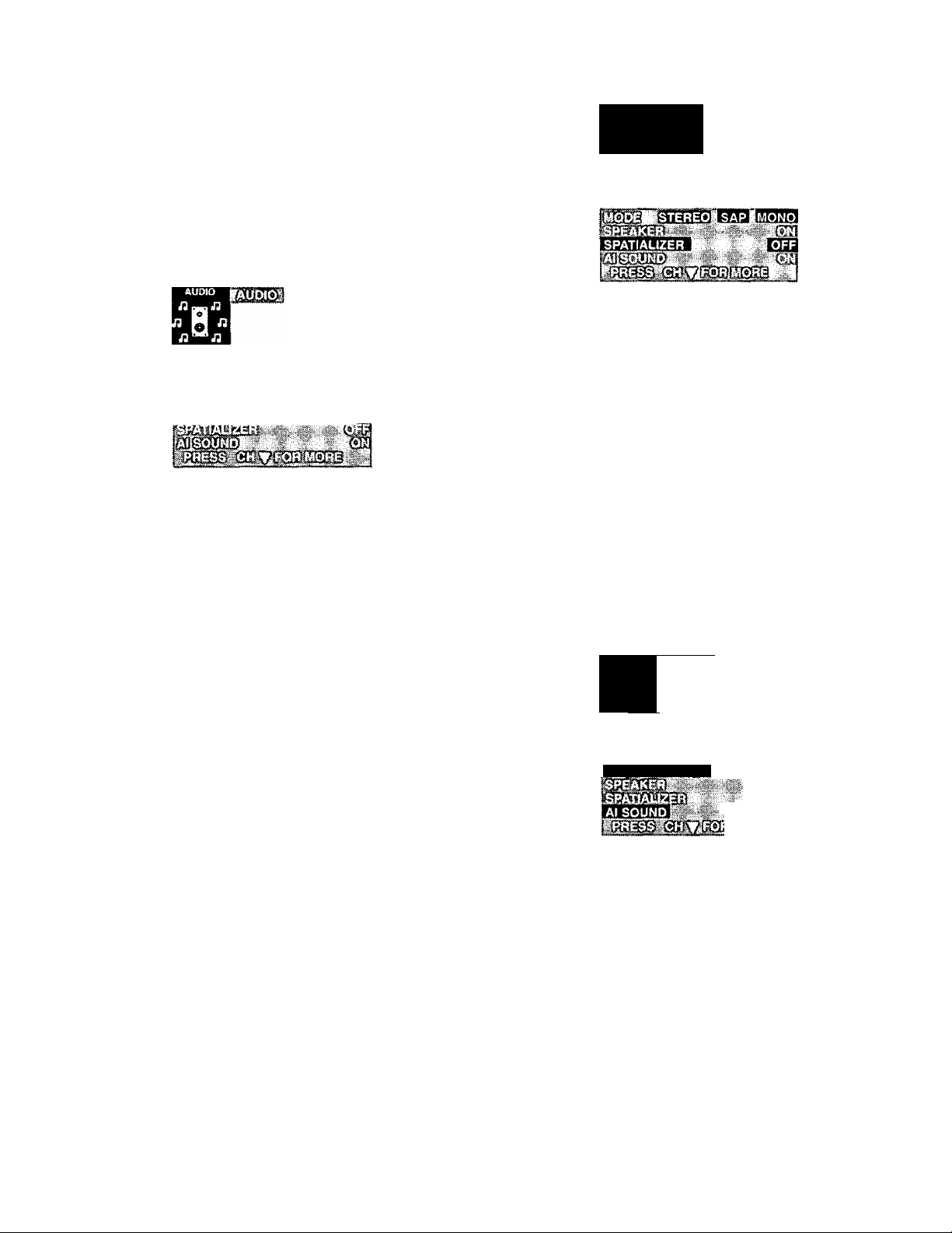
Audio Adjustments
Speaker [TV] — This feature is used to turn the
internal speakers “ON” or “OFF”. It is used when the
television is connected to an External Audio Amplifier.
(Refer to ‘To Audio Amp” Connection section for further
information.)
1. Press ^3 to display the Main Menu.
2. Press^orW and or ^ to select the Audio Icon.
3. Press (^3 to display the Audio Adjustment Menu.
lciaaRT!il3?i "W' lynl
4. Press ^ or
5. Press ^
OFF&FAO.
• ON - TV SPEAKERS operate normally.
• OFF&VAO (Variable Audio Output) - TV SPEAKERS
off, the sound output varies according to the TV
volume, use the TV remote to control the volume,
muting, bass, treble and balance of the External
Stereo System.
• OFF&FAO (Fixed Audio Output) - TV SPEAKERS off,
sound output is fixed.
^ to highlight SPEAKER.
^ to select ON, OFF&VAOor or
AUDîO
n g n
4. Press A or W to highlight SPATIALIZER.
5. Press or ^ to select SPATIALIZER ON or OFF.
6. Press ^3 twice to exit menus.
Al Sound —This feature is used to maintain constant
sound level when switching between programs with
different sound levels. For example, when the broadcast
program switches to a commercial, the commercial sound
level will be maintained close to the level of the broadcast
program. The Al SOUND selection appears only when the
SPATIALIZER is OFF.
1. Press to display the Main Menu.
2. Press A or W and or ^ to highlight the Audio
Icon.
3. Pressfegjj) to display the the Audio Adjustment Menu.
AUDIO
1 aa
" E
*aa
6. Press ^3 twice to exit menus.
Spatializer — spatializer is a system that makes
normal stereo sound more real. When an individual listens
to stereo, the sensation is that there is a wall of sound from
two speakers. Sound experts call this sensation or illusion,
"Psycho-Acoustic.” Our brain and ears work together to
combine the sounds from the two speakers to create the
illusion of a wall of sound. This television uses the
Spatializer feature to apply the Psycho-Acoustic illusion
to create a 3-dimensional sound from the two speakers.
When Spatializer is working, the sound feels as if it is
coming from multiple speakers, surrounding the listener.
The result is that the stereo system now sounds as though
the listener is actually in the studio or concert hall with the
performers.
1. Press to display the Main Menu.
2. Press ^ or ^ and ^ or ^ to
Icon.
3. Press i
to display the Audio Adjustment Menu.
highlight the Audio
PObiHSTEREO
Til
4. Press A or W to highlight Al SOUND.
5. Press or ^ to select Al SOUND ON or OFF.
6. Press (^3 twice to exit menus.
-20-
Page 21
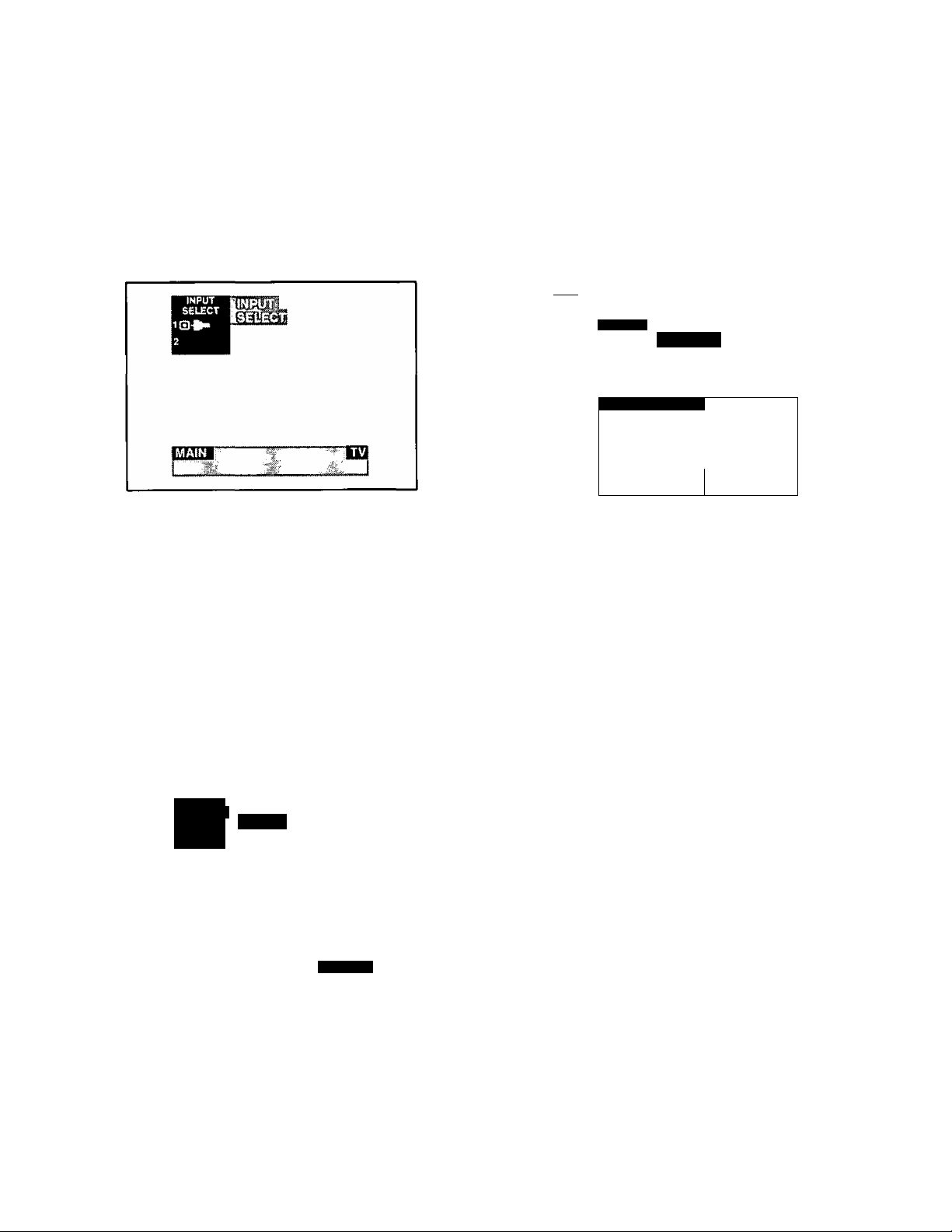
Input Select
Timer Feature
Main (Picture) Input Selection - This
feature is used to select TV Mode Operation or one of
three Video Inputs for the Main Picture (used with optional
accessory Video equipment).
1. Press ^3) to display the Main Menu.
2, Press ^ or ^ and or ^ to
Select Icon.
3. Press to display the Input Select Menu.
4. Press ^ or ^ to select TV, Video 1, Video 2 or Video
3 for Main Picture Input.
5. Press (^3 twice to exit menus.
highlight the Input
PIP Input Selection — This feature is used to
select TV Mode Operation or one of three Video Inputs for
the PIP (Picture in Picture) frame when the PIP frame is
displayed (used with optional accessory Video equipment).
Sleep Timer — This feature is used for automatic
turn OFF in 30, 60 or 90 minutes as desired.
NOTE: Display willflash3,2and 1 to indicate the last three
remaining minutes prior to turn OFF. To
deactivate, press or^ until “NO” is displayed.
1. Press [^3 to display the Main Menu.
2. Press ^ or and or to highlight the Timer
Icon.
3. PressCtej) button to display the Timer Control Menu,
Mwcn
mrnm
SLEEP TIMERB
, 5T1MËRÎ;
4.5.Press or ^ to select 30, 60 or 90 (minutes) for
Sleep Timer to be activated.
Press twice to exit menus.
NOTE: To deactivate Sleep Timer repeat steps 1 through
4. In step 4,' select “NO” instead of minutes.
Timer Control is not available when Auto Power
On is set.
■ '^-;hTIWIER2i:.,'.
OCX
1. Press (^3 to display the Main Menu.
2. Press ^ or ^ and or ^ to highlight the Input
Select Icon.
3. Press ^3 to display the Input Select Menu.
INPUT
SELECT
2
im
VIDEO 1
4. Press or ^ (when the PIP frame is displayed) to
highlight “PIP".
5. Press ^ or ^ to select TV, Video 1, Video 2 or Video
3 for the PIP frame Input.
6. Press (^3 twice to exit menus.
Special Feature:
Automatic turn “OFF’ after 90 minutes.
The TV has a special feature that will shut itself
OFF after 90 minutes when turned ON by the
program timer unless a function key is pressed
during the 90 minutes.
This feature is used to insure that the TV will not
remain ON unattended for an extended period of
time.
Programming the OFF timer will also cancel the
automatic OFF feature.
(Program) Timer — The (Dual Program) Timer
feature is capable of turning the TV ON to a desired
channel and then turning the television OFF at a
predetermined time.
NOTE: The clock and day must be set for this feature to
operate. (Refer to Set Up Menu to Set Time &
Day.)
1. Press
Press A or W and or ^
2.
Icon.
y) to display the Main Menu.
and or ™ to highlight the Timer
-21 -
Page 22
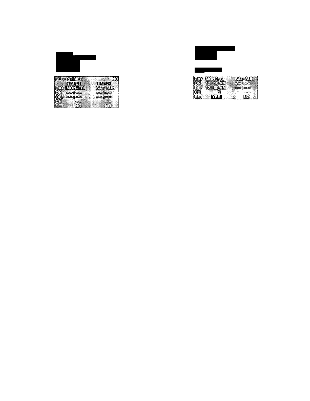
Timer Feature
(Program) Timer (Cont.)
3. Press lUssilJ to display the Timer Control Menu.
\wm
©
4. Press ^ or^ to highlight the TIMER 1 or TIMER 2
setting.
• Day or days to activate the Timer
• ON (time) - hours and minutes
• OFF (time) - hours and minutes
• CH - the channel the TV is tuned to when the ON Timer
activates.
• SET - NO (Timer feature will not activate)
- YES (Timer feature will activate)
5. Highlight the Timer 1 Day/Days option.
6. Press ^ or ^ to set the day or days for the TV to turn
ON.
The options for setting day are: (MON~FRI),
(SAT-SUN), (DAILY). (SUN), (MON), (TUE). (WED),
(THR), (FRI), (SAT). (EVR SUN), (EVR MON), (EVR
TUE), (EVR WED), (EVR THR), (EVR FRI), (EVR
SAT).
Eairai
0*
TiMERI
14. Press ^ to activate or ^ to deactivate Timer 1.
•YES=Feature is activated
•NO=Feature is not activated
15. Press W to set Timer 2 (if desired). Follow Steps 6
through 14.
16. Press (^3 twice to exit menus.
NOTE: Pressing ^
Timer Icon,
again will return you back to the
TIMEF12
HielpfiijHint^
• The Program Timer overrides the Sleep Timer.
• Program Timer can only access channels in
Program Channel Memory.
• “Set Time Firsf will appear on screen when trying
to set Timer Day Option without the clock being set.
• If the Program Timer “ON” functions while the set is
operating the set will automatically tune to the
channel designated in the Program Timer.
__________
7. Press ^ to highlight the ON (Hours/Minutes).
8. Press or ^ to set the time for the TV to turn ON.
9. Press W to highlight the OFF (Hours/Minutes).
10. Press or ^ to set the time for the TV to turn OFF.
11. Press ^ to highlight CH.
12. Press ^ or ^ to select a channel (from Program
Channel Memory) for the TV to be tuned to when it
turns ON.
13. Press
Wto highlight SET.
Lockout Features
Lockout Mode — This feature allows locking out
the following from viewing:
• Game - Lockout Channel 3 & 4 plus Video Inputs.
• Channel - Lockout up to 4 Channels.
• All - Lockout All Channels plus Video Inputs.
NOTE: This feature will Lockout your selection for up to 48
hours. Be sure to understand this feature before
using. Use a code that you will easily
remember.
1. Press to display the Main Menu.
2. Press ^ or ^ and ^ or ^ to highlight the Lock
Icon.
3. Presses to display the Lock Menu.
-22-
Page 23
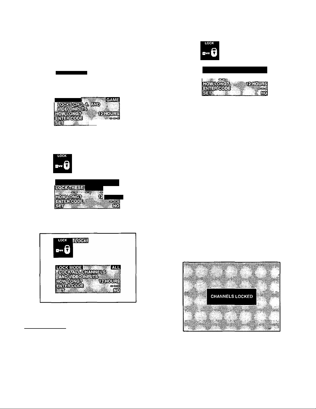
Lockout Features
Lockout Mode (Cont.)
NOTE: When the Lockout Menu is displayed, the Game
Lock option will be highlighted.
4. Press or ^ to select GAME, CH (CHANNEL) or
ALL.
LOCK
LOCK MODE
A—
Game Lockout Menu
(Channels 3 & 4 plus Video Inputs)
LOCK MODE mmm channel
HOURS
Channels Lockout Menu
(up to 4 Channels)
LOCK MODE mCL {CHANNEL
oci c=si
Step A
Press ^ to highlight “LOCK THESE CHANNELS”.
Step B
Then use the Remote Control Keyboard or or ^ to
select a channel you desire to lockout.
Step C
Press ^ to select next channel position.
StepD
Then repeat Step B & C until desired Channels are locked
out (up to 4 channels).
5. Press ^ to highlight “HOW MANY HOURS”.
6. Press ^ or ^ to select 12,24 or 48 (hours lockout
time).
7. Press ^ to highlight “ENTER CODE” then enter a 3
digit code by using the Remote Control Keyboard.
IMPORTANT NOTE: Use a code you can easily
remember.
All Lockout Menu
(All Channels plus Video Inputs)
Helpful Hintsi
NOTE: If a red “PG” appears in the upper right hand
corner, the selected channel or Video mode is
locked out.
NOTE: When the LOCK MODE CHANNEL is selected,
perform procedure Steps A through D.
8. Press ^ to select “YES” for Lock feature to be
activated “CHANNELS LOCKED” will display On
Screen.
Lock Feature Activated
-23-
Page 24
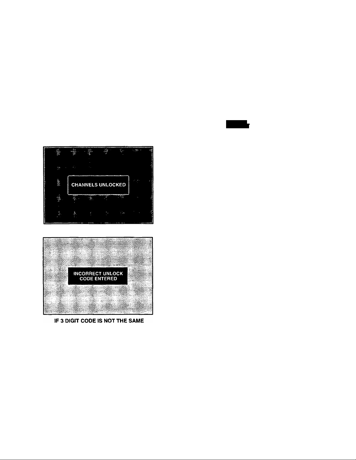
Lockout Features (cont.)
Favorite Channel Features
Unlock — Follow Steps 1 through 3 from previous sec
tion and enter same 3 digit code as in Step 7. Channel Un
locked display will appear.
HKl
B
imm. (ssm ^ .№@^(3
ENTER SAME 3 DIGIT CODE
Channel Scan — This feature is used to select
which Channels will be accessed when using A or
ALL or FAV (Favorite) Channels.
NOTE: Channels must be programmed into Favorite
Channel Select Memory first.
1. Press to display the Main Menu.
2. Press^ or^ and or^ to highlight the Favorite
Channel Icon.
3. Pressi
4. Press ^ or W to highlight CHAN SCAN.
to display the Favorite Channel Menu.
FAVORITE
CHANNEL
IF 3 DIGIT CODE IS THE SAME
5. Press ^ or ^ to select ALL or FAV (Favorite).
• ALL-The^orW will access all channels in Channel
Memory.
• FAV - The ^ or ^ will only access channels in
Favorite Channel Select Memory.
6. Press ^3 twice to exit Menus.
NOTE: Pressing
Favorite Channel Icon.
again will return you back to the
HelpfuliHIlits:
NOTE: After Auto Channel Program the first 15
channels selected will automatically be put into
Favorite Channel memory, if space is available.
-24-
Page 25
Favorite Channel Features
Channel Caption Features
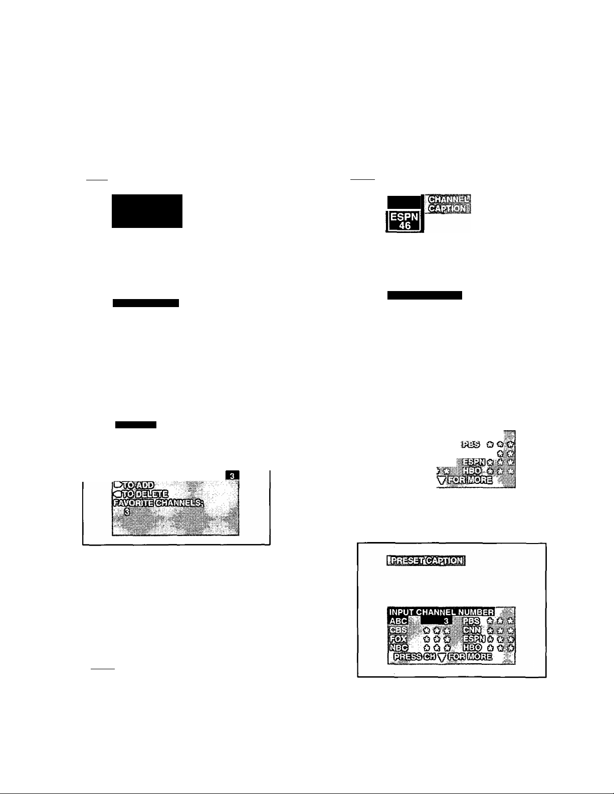
Favorite Channel Select — The Favorite
Channel Programming allows you to program up to 15 of
your favorite channels. You can use the CH buttons on the
Remote Control to scan channels without going through
channels you do not normally view.
1. Pressto display the Main Menu.
2. Press^^or^^and*^or^^ to highlight the Favorite
Channel Icon.
3. Press fesiJ} to display the Favorite Channel Menu.
FAVORfre
CHANNEL
^'0-8
FAV CH SELECT
4. Press A or ^ to highlight CHAN SCAN. Then,
press or ^ to select FAV option for Favorite
Channels setting.
Preset Caption — This feature allows you to select
from 56 preset captions, and assign corresponding
channel numbers utilized in your area. Captions are easily
assigned to the channel numbers you select by following
the steps outlined below.
1. Press to display the Main Menu.
2. Press orand orto highlight the Channei
Caption Icon.
3 Press CLssij] to display the Channel Caption Menu.
CHANNEL
CAPTION
PRESET CAPTION
4. Press A or W to highlight PRESET CAPTION.
5. Press or ^ to display the Preset Caption Menu.
5. Press A or ^ to highlight“FAV CH SELECT’.
6. Press or ^ to display the Favorite Channel Select.
7. Enter the channel number you wish to add or delete
from Favorite Channel Memory (using the Remote
Keyboard or A or W).
8. Press ^ to add or press ^ to delete charinel from
Favorite Channel Memory.
9. Repeat Steps 6 and 7 to add or delete channels (up to
15 channels may be stored in Favorite Channel
Memory).
10. When you are done with adding and deleting channel,
presses twice to return to normal viewing.
11. Press A or to scan through the Favorite
Channels you programmed.
O O O '
6. Use the Remote Control keyboard, to assign the
channel number to the Channel Caption in your area
(Refer to your local TV guide).
7. Press ^ to select a different Preset Caption, then
repeat step 6 until all desired Preset Captions have
assigned channel numbers.
-25-
Page 26
Channel Caption Features
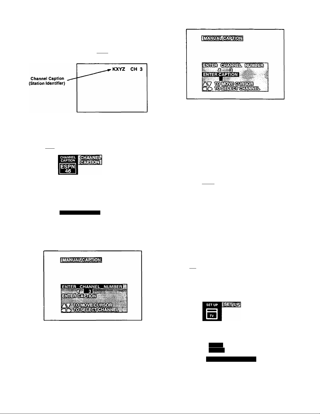
Manusl Caption — The Channel Caption (Station
Identifier) allows you to input the call names of up to 30
stations into memory (using up to 4 characters). The call
name will then display, along with the channel number
when changing channels or pressing
1. Press to display the Main Menu.
2. Press^^or^^ and*^or^^ to highlight the Channel
Caption Icon.
8. Press or ^ to select first character in channel
caption (STATION IDENTIFIER).
9. Press ^ to move to second character position, and
repeat steps 8 and 9 until the complete caption is
entered (up to 4 characters).
3. Press (feJ) to display the Channel Caption Menu.
MANUAL CAPTION
4. Press ^ to highlight MANUAL CAPTION.
5. Press or ^ to display the MANUAL CAPTION
menu.
10. Press ^ or repeatedly to highlight ENTER
CHANNEL NUMBER. Then repeat steps6 through 10
to continue adding channel caption (STATION
IDENTIFIERS).
11. Press (^3 three times to exit menus.
Note: Pressfegsaj) again to return to Channel Caption
Icon.
Set Up Features
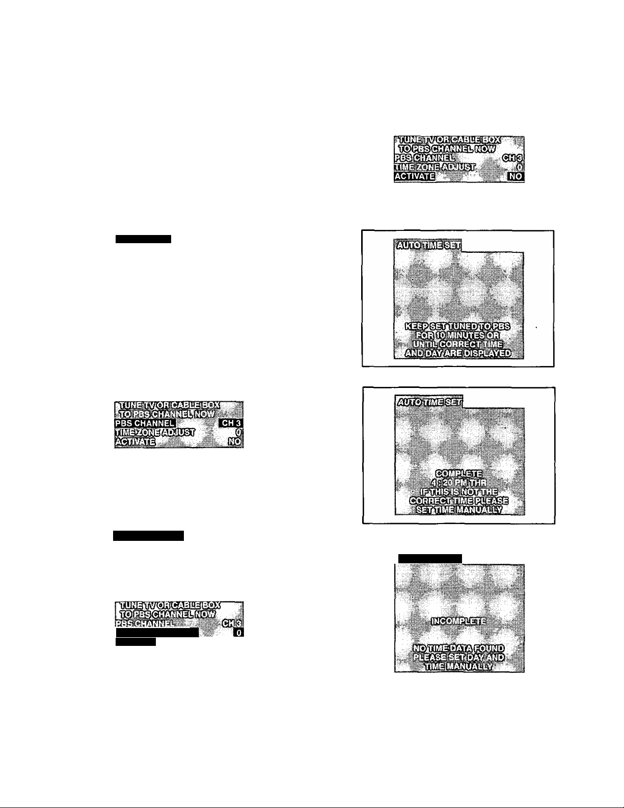
Clock (Auto) — This feature automatically adjusts
the TV dock to the correct time whenever the TV is tuned
to a PBS (Public Broadcasting Service) station for 10
minutes or until the. correct time and day are displayed
(Refer to your local TV guide for PBS channel number).
NOTE: A plus or minus one-hour offset can be
programmed to adjust the clock when there is a
time zone difference between the PBS TV station
and the viewer.
1. Press [¿3 to display the Main Menu.
2. Press ^ or ^ and or ^ to highlight the Set Up
Icon.
3. Press to display the Set Up Menu.
Use the Remote Control Keyboard or or ^ to
6.
enter channel number your wish to assign a channel
caption (STATION IDENTIFIER).
7.
Press'^ to highlight ENTER CAPTION.
-26-
LOCK
IS
lllll
mcsfi C3i:SI. :
Page 27
Set Up Features
Clock (Auto) (cont.)
4. Press ^ and ^ or ^ to highlight CLOCK.
5. Press or ^ to select AUTO ( if necessary).
6. Press W to highlight AUTO TIME SET
AUTO TIME SET
7. Press^or^ todisplaythe AUTOTIMESETMenu.
8. Press A to highlight PBS CHANNEL.
yy >yir
13. Press or ^ to display the AUTO TIME SET
ACTIVATE Menu.
9. Tune TV or Cable Box to PBS channel, using the
Remote Control Keyboard to enter PBS channel
number.
10. Press ^ to highlight TIME ZONE ADJUST.
TIME ZONE ADJUST
AGTVATe
WAITING FOR CORRECT TIME AND DAY
COMPLETED READ MENU
autotime;sb:
11. Press ^ for minus one-hour offset or ^ for plus
one-hour offset (if necessary).
12. Press ^ to highlight ACTIVATE.
INCOMPLETE READ MENU
14. Press ^3 four times to exit menus.
-27-
Page 28
Set Up Features
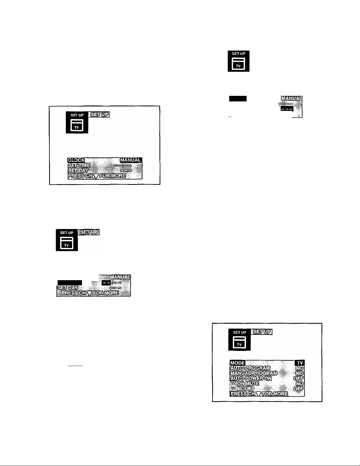
Clock (Manual) — Clock (when set) will display On
Screen at initial turn on, after a channel change and when
pressing It must be set in order to operate the dual
Timer feature.
1. Press (^3 to display the Main Menu.
2. Press A or ^and'€ or ^ to highlight the Set Up
Icon.
3. Press
4. Press ^ or ^ to highlight CLOCK.
5. Press ^ or ^ to select MANUAL.
6. Press ^ or ^ to highlight SET TIME.
to display the Set Up Menu.
SET TIME
--------
3. Press ^3) to display the Set Up Menu.
mom
1
4. Press A or W to highlight SET DAY.
5. Press or ^ to select proper day of the week.
6. Press ^3 twice to exit Menus.
Mode (TV or Cable)
IMPORTANT NOTE: The proper input mode must be
selected for the type of signal at the antenna input.
• TV is used when the television is not connected to a
Cable TV System, for example, when using a VHF/UHF
antenna (Channels 02-69).
• CABLE is used when the television is connected to a
Cable TV System and when not using a Cable Box
(Channels 01-125).
NOTE: Some Cable TV Systems encode (scramble)
program material on specific channels. A cable
company supplied decoder is required to
reproduce an acceptable picture. Certain Cable
TV Systems offset some channels to reduce
interference. It will be necessary to use the cable
company supplied converter to receive these
specific channels.
1.
Press ^3 to display the Main Menu.
7. Press ^ or ^ to Set Hours (set AM/PM
accordingly).
8. Press W to highlight minutes position.
9. Press or ^ to set minutes.
10. Press I
NOTE: Pressing[tUSUl
Up Icon.
twice to exit Menus.
I
again will return you back to the Set
Set Day — The day of the week must be set in order to
operate the Dual Timer feature.
1. Press to display the Main Menu.
2. Press ^ or ^ arid‘s or^ to highlight the Set Up
Icon.
2.
Press ^ or^ and or ^ to highlight the Set Up
Icon.
3. Press to display the Set Up Menu.
4. Press A or W to highlight Mode.
5. Press or ^ to select TV or CABLE.
6. Press ^3 twice to exit menus.
-28-
Page 29
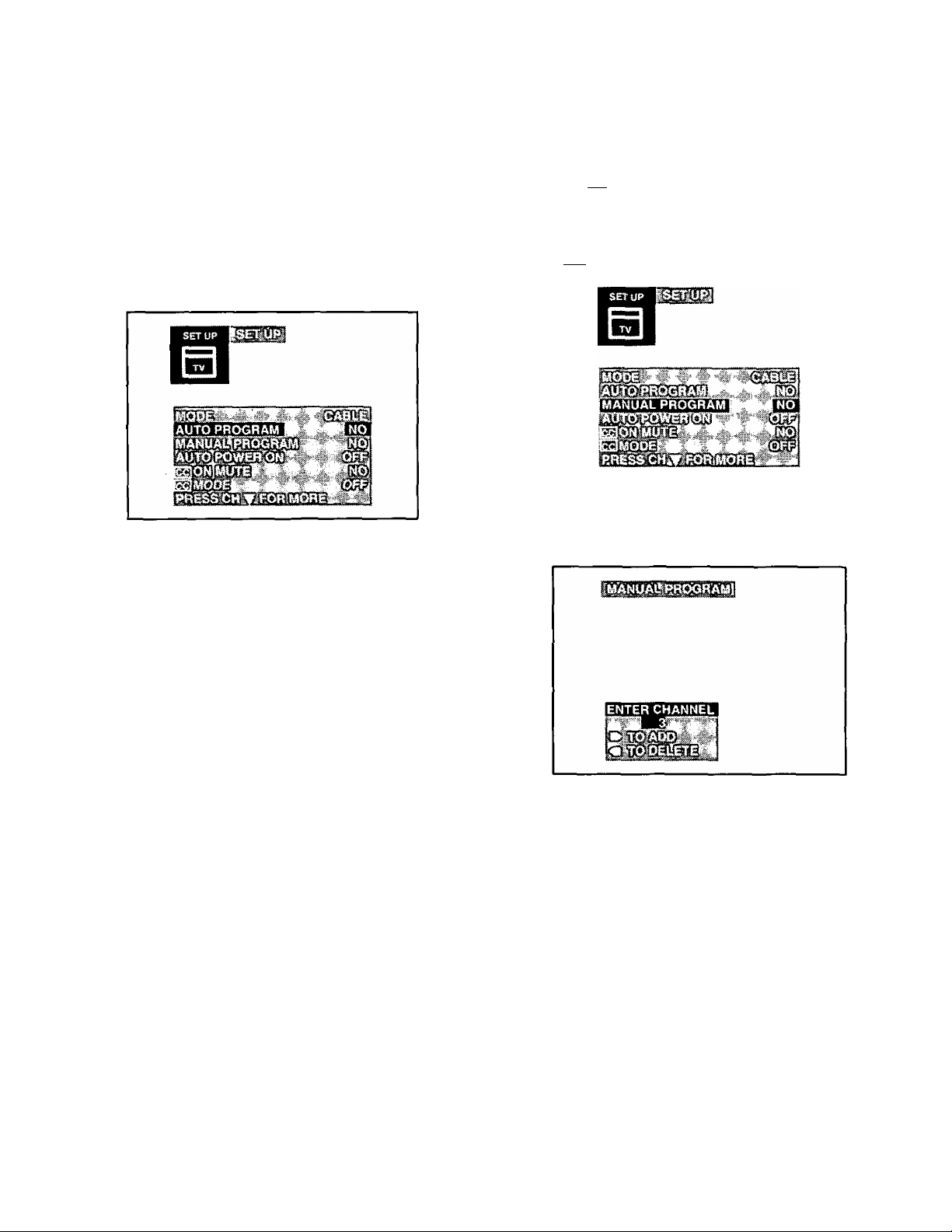
Set Up Features
Auto Programming - The Auto Programming
feature allows you to place all channels with a video signal
into Channel Scan Memory. When you press A or^,
only those channels with a video signal will be accessed.
NOTE: TV or Cable Tuning mode must be set properly for
your system.
1. Press
2. Press ^ or
Icon.
3. Press to display the Set Up Menu.
4. Press A or ^ to highlight AUTO PROGRAM.
to display the Main Menu.
and or^ to highlight the Set Up
Manual Programming - This feature allows
you to select which channels are placed into Channel
Scan Memory so when you press A or ^ only those
channels you desire will be accessed.
1. Press the (US to display the Main Menu.
2. Press A or ^ and or ^ to highlight the Set Up
Icon.
3. Press ifeO) to display the Set Up Menu.
4. Press A orto highlight MANUAL PROGRAM.
5. Press or ^ to display Manual Programming
Menu.
5. Press or ^ to start Auto Programming Scan.
Channels will automatically advance until all channels
have been scanned.
• Channel numbers with video signal present will turn
blue which indicates stored in Channel Scan Memory.
6. Press ^3 twice to exit menus.
NOTE: Some channels with very weak signals may be
locked into memory. These must be deleted
manually using the Manual Program feature.
Helpful Hints:
After Auto Programming:
Blue channel number indicates channel is in Channel
Scan Memory.
All channels are available by direct access using the
Keyboard numbers “0 through 9”.
After Auto Programming Scan has completed, up to 15
channels will be programmed into the FAVORITE
Channel Scan if space is available. Any original
channels that were programmed into FAV CHANNEL
will remain. (Refer to Favorite Channel Scan for
deleting unwanted channels.)
6. Use the Remote Control Keyboard numbers “0
through 9” or A or ^ to select channels.
7. Press ^ to add channel(s) to memory (blue). Press
the ^ to delete channel(s) from memory (yellow).
8. Repeat Steps 6 and 7 to continue adding or deleting
channels.
9. Press ^3 twice to exit menus.
-29-
Page 30
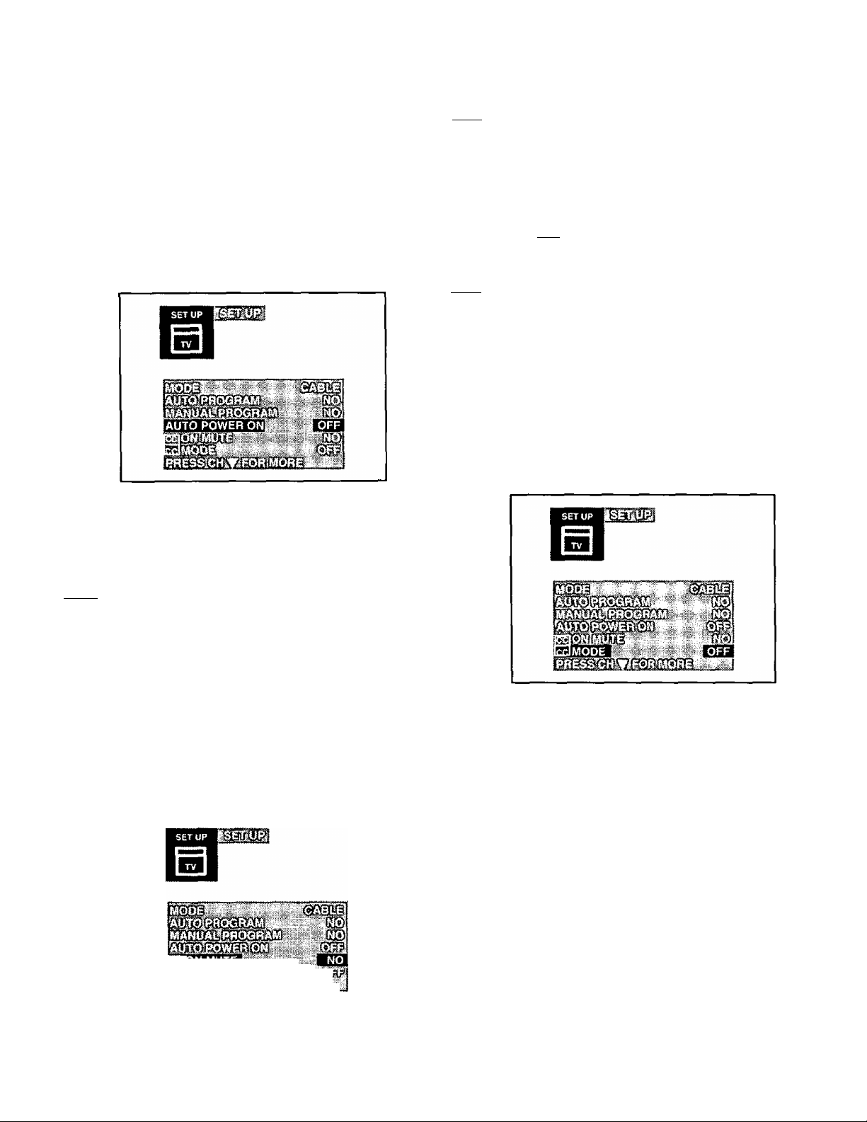
Set Up Features
Auto PoW©r On - Automatically turns the
television on when a VCR, Cable Box, etc., are powered.
The Television needs to be plugged into the switched
outlet of the device. Setting the Auto Power On feature will
cancel the time and timercontrol settings. The Main Menu
Icon for the TIMER CONTROL will be replaced with an
EXIT Icon.
1. Press to display the Main Menu.
2. Press A or Wand^ or^ to highlight the Set Up
Icon.
3. Press to display the Set Up Menu.
4. Press A or to highlight AUTO POWER ON.
5. Press or^ to select NO (OFF), C1, C2, C3 or C4.
Recommended Set Up for Closed Caption when using
• CC0NMUTE:C1
• CC MODE: OFF
6. Presses twice to exit menus.
7. Press when the program being viewed is
broadcast with Closed Caption to activate.
NOTE: Press again to deactivate.
fee] Mode —This television contains a built in decoder
that is capable of providing a visual depiction of the audio
portion. The program viewed must include Closed
Captioning (CC) for the television to display it. CC is
displayed in the form of text across the screen (white or
colored letters on a black background). It allows the viewer
to read the dialogue of a television program or other
information.
1. Press to display the Main Menu.
2. Press ^ or W and or ^ to highlight the Set Up
Icon.
3. Press ^3) to display the Set Up Menu.
5. Press or to select SET.
6. Presses twice to exit menus.
|CC| On Mute - Activates the On Screen Closed
Caption feature when the^^^^ on the Remote Control is
pressed. To deactivate press again.
NOTE: This feature only functions when the Close
Caption Mode is in the “OFF” position. The
program being viewed must be broadcast with
Closed Caption. (Refer to your local TV guide.)
1. Press to display the Main Menu.
2. Press ^ or W and* *^ or^ to highlight the Set Up
Icon.
3. Press ^3
4. Press A or W to highlight CC ON MUTE.
to display the Set Up Menu.
..
^ ,
4. Press A or^ to highlight CC MODE.
5. Press or ^ to select OFF, C1 ,C2, T1, T2, C3, C4,
T3 orT4.
• CAPTION OFF - Use when Closed Caption is not
desired.
• CAPTION C1 - For video related information that can
be displayed (up to 4 lines of script on the screen, where
it does not obstruct relevant parts of the picture). Script
can be in any language.
• CAPTION C2 - Another mode used for video related
information.
• CAPTION C3 and C4 - Other modes used for video
related information.
• TEXT T1 - Blanks out a large portion of the picture on
the television screen, and displays program guide or
any other information currently being transmitted.
• TEXT T2, T3 & T4 - Other modes that display
information and blank out a large portion of the picture
on the television screen.
6. Press twice to exit menus.
-30-
Page 31
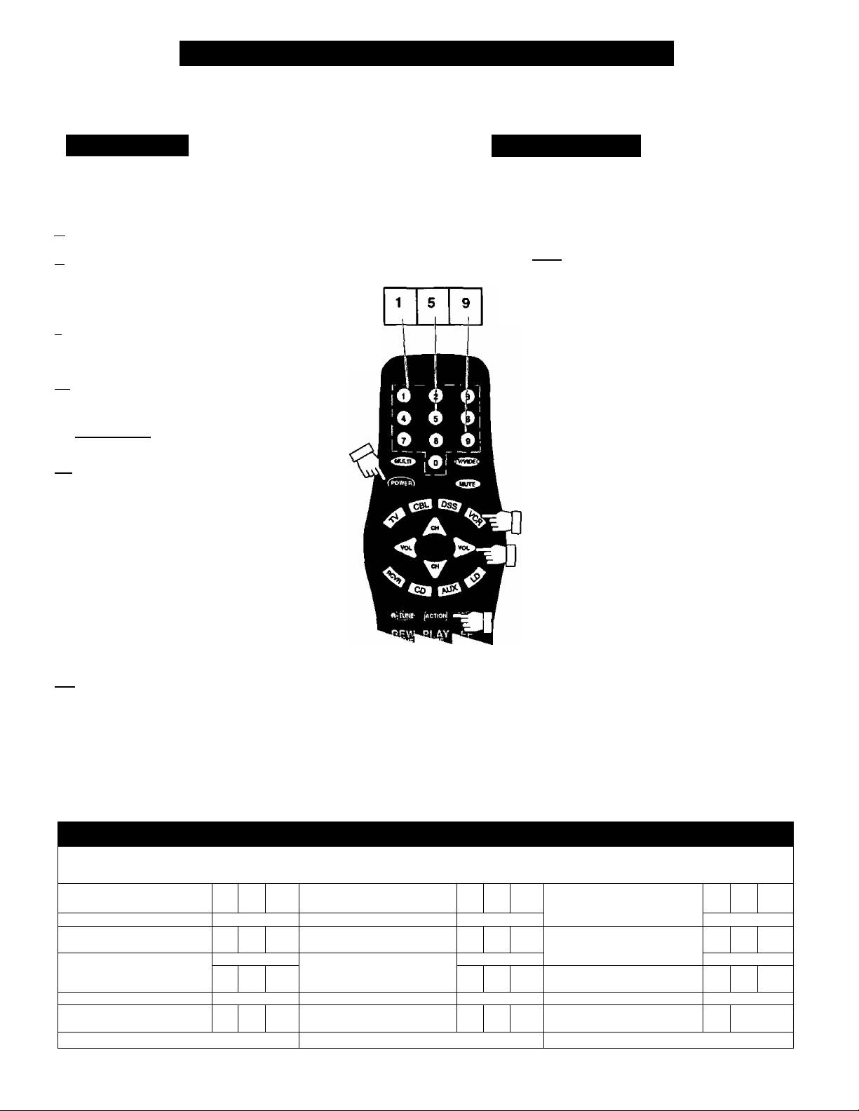
Programming the Home Theater Remote
The remote control can be set to control other manufacturers components, by utilizing the MODE SELECTION
BUTTONS for CABLE, DSS, VCR, RCVR (a Receiver or Amplifier), CD, LD, and AUX (for Cassette Players, Second
VCR or a DVD.)
Code Known
Use the following procedure for setting up the
remote control using the numerical buttons
when the component’s remote code is known.
rn Determine the brand of the component.
in Identify the code(s) associated with the
brand from the infrared code index (see
following pages). Record all possible
codes.
n Confirm that the component is plugged
in and operating properly, then turn it
OFF.
[4Ì Press and hold the ^3) button, then
the button so that both are
pressed at the same time for
15 seconds. All Mode buttons wiil
flash. Then let go of the buttons.
fSl Press the appropriate Mode button
for the component. The pressed
button will illuminate steadily. All
other buttons will go out.
Enter the 3-digit code, by using the
Remote Control Keypad “0”
through ”9” buttons. If a proper
code was entered, the Mode button
will blink twice then go out.
Bvirihe remòte
ITI Press the button to test the remote. If
the correct code is setup for the
component (in step [Sl)i the component
wiil turn on.
NOTE: Some brands have multiple codes.
Repeat the procedure using another
listed code until the component
responds correctly.
m
Code From
Index Sheet
EUR511060A
Code Unknown
Use the following procedure for setting up the
remote control when the component's remote
access code is not known. This procedure
uses the "sequence method”.
[01 Confirm that the component is plugged
in and operating properly, then turn it
OFF.
m Press and hold the button,
then the button so that both
are pressed at №e same time for at
All Mode buttons
will flash. Then let go of the buttons.
Press the appropriate Mode button
for the device. The pressed button
will illuminate steadily. All other
buttons will go out.
1
Press the button to step
over to the next code.
Press the button to test the
remote. If the correct code is
sent, the component will turn on.
Once the correct code is found,
press the button
to store the code.
Repeat from step El above until the
proper component code is found. It
may take several attempts before
the correct code is found.
NOTE: If an incorrect code is entered, or
when the operation is not
completed within 30 seconds, the
settings will not change.
Infrared Remote Codes for Specific Components
Helpfut^lnt:, . Write down the code numbers for your components in the space provided below. This
^ williervei^ a hihdy reference whenever you need toreprb^am your remote control.
CABLE
Cable TV Converter Box
DSS
Digital Satellite System
Other Component
□
I
n n
VCR
Video Cassette Recorder
RCVR
Receiver or Amplifier
Other Component
n
CD
Compact Disc Player
LD I
Laser Disc Player
other Component
1
I Other Component
II Other Component
II Other Component |
-31 -
n
!
n
i
I
I
Page 32
VCR Infrared Codes Index
The Universal Infrared Remote Control is capable of operating many brands of VCRs. Refer to the Programming the
Remote Control section for procedures.
NOTE: The Universal Remote Control memory is limited; therefore, some models of VCRs may not operate. The
Universal Remote Control is not designed to control all features that are available in all models.
NOTE: After entering the proper infrared code, press the Remote VCR (A) Selection Mode button. A second VCR can
be activated using the same codes, from AUX Selection Mode button. Then refer to the Remote Control
Key Functions section, for Remote VCR and VCR 2 function key listing.
Code Index for VCRs
VCR Brand
Admiral
Aiwa
Akai
Audio Dynamic
Bell & Howell
Broksonic 081,136 ProScan 000, 001,002,125,
Canon
Citizen 006
Craig
Curtis Mathes
Daewoo
DBX 010,011,240
Dimensia 300
Emerson 003, 051,080, 081, Realistic
Fisher
Funai
GE
Goldstar 006
Go Video
Hitachi 000, 125,300,
Instant Replay
Jensen 240 008,
JVC
Kenwood
LXI 000, 005, 006, 007,
Magnavox
Marantz 010,011,240
Marta 006 Sylvania
Memorex 009,130 Symphonic 137
MGA 230,241,242, 243, Tashiro 006
Minolta
Mitsubishi 230, 241.242, 243. Technics 100, 101,125, 130
Muititech 004,137,330 Toshiba 001,310
NEC
Olympic
Optimus
Orion 081, 136
Panasonic 100,101,.125, 130 Zenith 290
Penney 000. 005,010, Oil,
Code(s) VCR Brand Code(s)
200 Pentax 000,011,300
137,160
014,015,016,142 137. 150
011,240
005,013
125,135
005, 006,141
130, 137, 300
001, 130, 250 RCA 000, 001,002,125,
135, 136, 243, 250
005, 007, 008, 009
081, 136, 137 Sansui
130,170, 300
220
125, 130, Sears 000, 005, 006, 007,
010,011,190,240 Shaintom 050
006, 010,011,240
008,009,137 Singer 050
025, 130,150
330, 340
000,300
330, 340
010,011, 190. 240
125,130
006, 200, too, 140
130,240, 300
Philco
Philips
Pioneer 125
Quasar
Radio Shack
Samsung 002,004, 220
Sanyo
Scott 001,002, 004, 009,
Sharp
Signature 2000
Sony
SV2000 137
Tatung
Teac 010,011, 137. 240
Teknika
Vector Research Oil
Wards
Yamaha
081. 125,130,136,
125, 130, 150
130, 150,300,310
100, 101,125, 130
005, 009, 130, 137,
170,210, 241
130, 150, 170,300,
310
005, 009, 130, 137,
210,241
081, 136, 240
005, 009
081,136, 230, 241.
330,340
200, 210
137, 200
140, 141,142
125, 130, 137, 150
010,011,240
130, 137
006, 009,200,210,
290
005,010,011,240
-32-
Page 33
Cable Converter Box and CD Players
Infrared Codes Index
The Universal Infrared Remote Control is capable of operating many brands of Cable Converter Boxes and CD Players.
Refer to the Programming the Remote Control section for procedures.
NOTE: The Universal Remote Control memory is limited; therefore, some models of Cable Converter Boxes and CD
Players may not operate. The Universal Remote Control is not designed to control all features that are available
in all models.
NOTE: After entering the proper infrared code, press the Remote CBL Selection Mode button (A). Then refer to the
Remote Control Key Functions section, for Remote CBL function key listing.
Codes for Cable Converter Box
Brand of
Cable-TV Box
Code(s)
Brand of
Cable-TV Box
Code(s)
ABC
Archer
Cableview 005, 544
Citizen
Curtis
Diamond
Eagle
Eastern
Gcbrand
Gemini
General Instrument 122,360, 520, 521,
Hamlin
Hitachi
Jerrold
Macom 003, 004, 005
Memorex
Movietime
Oak
Panasonic
Paragon
530
531,544
005,522
130, 131
530, 531, 544
541
560
005,544
522
522, 530, 531,532,
533
130,350, 720, 730,
731,900
003, 530
122, 360, 520,521,
522, 530,531,532,
533
542
005,544
002,702,710
120,121,132
281
Philips
Pioneer
Pulsar
Puser
RCA
Realistic
Regal
Regency
Rembrandt 005, 544, 702
Samsung
Scientific Atlanta 122,130,131
SImark
Sprucer
Stargate
Teleview
Texscan
Tocom
Toshiba
Unika
Universal
Videoway
Viewstar
Zenith
1 Zenith/Orake Satellite 000 |
006, 007, 540,
541,542
001,260
005,544
544
170, 220
544
130,350, 720,
730, 731,900
560
005
001,005
005, 121
005,544
001,005
810
700, 701
004
531,544
522, 544
006
541,542
000, 260, 281
NOTE: After entering the proper infrared code, press the Remote CD Selection Mode button A). Then refer to the
Remote Control Key Functions section, for Remote CD Players function key listing.
Codes for CD Players
Brand of
CD Players
Admiral
Aiwa
Carver
Denon
Emerson
Fisher
Garrard
Harman/Kardon 059,060
Hitachi
Jensen
JVC
Kardon
Kenwood
LXI
Magnavox
Marantz
McIntosh
Nakamichi
Onkyo
Code(s)
110
162, 164
150,151
200
172
005
057
007
163
190,191,270
058
000,001,050, 270
165
150,161
151
060
032
053,054
-33-
Brand of
CD Players
Optimus 030, 057, 059,
Panasonic
Philips
Pioneer
Quasar 100, 101, 130
RCA
Sansui
Sanyo
Scott
Sharp
Sherwood
Sony
Soundesign
Teac 051,055, 057
Technics
Victor
Yamaha
Code(s)
061
100,101,130
150,151
030
160, 170,
171,500
032, 050, 320
005
032, 050, 320
200, 201
059
140
220
100, 101, 130
190, 191,270
002, 003, 004
Page 34
Cassette Deck, Receivers, and Amplifiers
Infrared Codes Index
The Universal Infrared Remote Control is capable of operating many brands of Cassette Deck, Receivers, or Amplifiers.
Refer to the Programming the Remote Control section for procedures.
NOTE: The Universal Remote Control memory is limited; therefore, some models of Cassette Deck, Receivers, and
Amplifiers may not operate. The Universal Remote Control is not designed to control all features that are
available in all models.
NOTE: After entering the proper infrared code, press the Remote AUX Selection Mode button Then refer to the
Remote Control Key Functions section, for Remote Cassette Players function key listing.
Code Index for Cassette Deck
Brand of
Cassette Deck
Aiwa
Denon
Fisher
Jensen 657 Sansui 631,653
JVC
Kenwood
Marantz 751 Teac 653, 654
Nakamichi
Onkyo
Panasonic
Code(s)
760,761,762
800
603 RCA 763, 770, 771
780,781 Sharp 800 .
600,650
631 Technics
651,652, 656
700, 701,730
Brand of
Cassette Deck
Philips 751
Pioneer 630
Sony
Yamaha
Code(s)
740
700, 701,730
601,602
NOTE: After entering the proper infrared code, press the Remote RCVR Selection Mode button (H<>}<). Then refer to the
Remote Control Key Functions section, for Remote Receivers/Amplifiers function key listing.
Code Index for Receivers and Amplifiers
Brand of Receiver /
Amplifier
Code(s)
Brand of Receiver /
Amplifier
Code(s)
Admiral 110
Aiwa
Denon
Fisher 004
Garrard
Harman
Jensen 164
JVC
Kenwood
Magnavox
Marantz
McIntosh
Nakamichi
Onkyo
Optimus
160, 161
200, 201,202
055
150, 057
190, 191
000, 050
162
151
058
031
151, 156
003, 162, 170, 171
Panasonic 100, 101,130
Philips 150
Pioneer 030, 032
Quasar 100, 101,130
RCA
Sansui 003, 053, 320
Sharp
Sony 140
Soundesign
Teac
Technics
\flctor
Yamaha 001,002
003, 130,162, 170,
171
200, 203
220
053, 054, 055
100, 101,130
190,191
-34-
Page 35
Laser Disc, DSS (Digital Satellite System),
and DVD (Digital Videodisc)
Infrared Codes Index
The Universal Infrared Remote Control is capable of operating selected brands of Laser Disc, DSS Digital Satellite
System, and DVD (Digital Videodisc). Refer to the Programming the Remote Control section for procedures.
NOTE: The Universal Remote Control memory is limited; therefore, some models of Laser Disc, DSS Digital Satellite
System, and DVD (Digital Videodisc) may not operate. The Universal Remote Control is not designed to control
all features that are available in all models.
NOTE: After entering the proper infrared code, press the Remote LD Selection Mode button (O). Then refer to the
Remote Control Key Functions section, for Remote Laser Disc function key listing.
Codes for Laser Disc
Brand of
Laser Disc Code(s)
Denon
Hitachi
Kenwood 002, 003
Marantz 370
Mitsubishi 370
NEC
Panasonic too. 101, 135, 380
Philips 150
Pioneer
ProScan
370
000
370
370
370
Brand of
Laser Disc
Quasar
RCA
Samsung
Sanyo 370
Sharp
Sony
Teac 370
Toshiba 370
Yamaha
Code(s)
100,101,135, 380
370
160
200
140,141,142,143
001
NOTE: After entering the proper infrared code, press the Remote DSS Selection Mode button {OO). Then refer to the
Remote Control Key Functions section, for Remote DSS function key listing.
Codes for DSS (Digital Satellite System)
Brand of
Satellite Code(s)
GE
Panasonic
RCA
Sony
170
100
170
390
NOTE: After entering the proper infrared code, press the Remote AUX Selection Mode button {★ ). Then refer to the
Remote Control Key Functions section, for Remote DVD function key listing.
Codes for DVD (Digital Videodisc)
Brand of
DVD Code(a)
Panasonic
-35-
702
Page 36
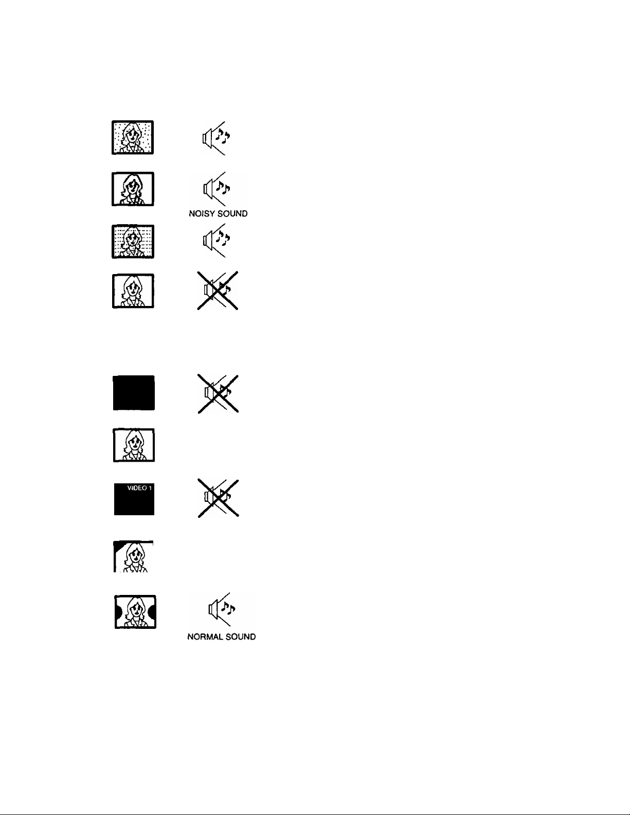
Troubleshooting Chart
Before you call for service, determine the symptoms and make a few simple checks shown below.
Symptoms
Picture
Sound
- ANTENNA LOCATION, DIRECTION AND/OR CONNECTION
Check
SNOWY PICTURE
MULTIPLE IMAGE
INTERFERENCE
NORMAL PICTURE
NO VIDEO
NO PICTURE
NO COLOR NORMAL SOUND
NOISY SOUND
NOISY SOUND
NO SOUND
NOISY SOUND
NO SOUND
ANTENNA DIRECTION AND/OR LOCATION
ANTENNA LEAD-IN WIRE
ELECTRICAL APPLIANCES, MOTORS, LIGHTS, CARS AND
TRUCKS, AND MEDICAL EQUIPMENT
VOLUME CONTROL SETTING
MUTE CONTROL (IF APPLICABLE)
TRY ANOTHER CHANNEL
TV SPEAKER SWITCH (IF APPLICABLE) IN THE OFF POSITION
TV OR CABLE TUNING MODE SET TO PROPER SETTING
ANTENNA INPUT CORRECT (IF APPLICABLE)
CHECK THAT AC POWER LINE IS PLUGGED INTO AC OUTLET
BRIGHTNESS AND AUDIO CONTROLS SET IMPROPERLY
TRY ANOTHER CHANNEL
COLOR CONTROL SETTINGS
TRY ANOTHER CHANNEL
BLACK PICTURE NO SOUND
DISCOLORATIONNNORMAL SOUND
DISCOLORED
PICTURE
CHK
%
CHK MODE
NORMAL SOUND
Panasonic Consumer Electronics
Company, Division of Matsushita
Electric Corporation of America
One Panasonic Way
Secaucus, New Jersey 07094
- TV IN VIDEO MODE WITH NO SIGNAL
- ADJUST GEOMAGNETIC CORRECTION LOCATED IN
THE SET-UP MENU (IF APPLICABLE)
MOVE UNSHIELDED SPEAKERS AWAY FROM PICTURE TUBE
TURN OFF SET. ALLOW TO COOL. TURN SET BACK ON
PRESS AND HOLD ACTION AND POWER BUTTONS ON THE
CONTROL PANEL AT THE SAME TIMÉ FOR 5 SECONDS. SCREEN
WILL SHUT OFF, THEN TURN BACK ON. TV WILL BE SET TO
CHANNEL 3 AND CYCLE THROUGH A SPECIAL TEST
Panasonic Sales Company,
Division of Matsushita Electric
of Puerto Rico Inc. (“PSC”)
Ave. 65 de Infanteria, Km 9.5
Panasonic Canada Inc.
5770 Ambler Drive
Mississauga, Ontario L4W 2T3
Canada
San Gabriel Industrial Park
Carolina, Puerto Rico 00985
 Loading...