

Panasonic CT-35S31S, CT-35S21S Operating Instructions Manual
Color Television
Operating Instructions
®
I H I
=
Read these instructions completely before operating this set.
Contents subject to change without notice or obligation.
Printed in U.S.A.
TQB2A0878

Safety Instructions
CAUTION
CAUTION: To reduce the risk of electric shock do not remove cover or back. No
user_-serviceable pails inside. Refer servicing to qualified service personnel.
The lightningflash withar- The exclamation pointwithin
,_ row-head within a triangle A a triangle is intended to tell
is intended to tell the user ,_ the userthat importantoper-
that partsinsidethe product ating and servicing instruc-
are arisk ofelectric shockto tions are in the papers with
persons, the appliance.
Note To CATV System Installer: This reminder is provided to call the CATV system installer's attention to Article
820-40 of the NEC that provides guidelines for proper grounding and, in particular, specifies that the cable ground Shall be
connected to the grounding system of the building, as close to the point of cable entry as practical.
Safety Instructions For Television Receivers
1. Read and apply the operating instructions provided with your television receiver.
2. Read all of the instructions given here and retain them for later use.
3. Unplug this television receiver from the wall outlet before cleaning. Do not use liquid or aerosol cleaners. Use a damp
cloth for cleaning.
4. Do not use attachments not recommended by the television receiver manufacturer as they may cause hazards.
5. Do not use this television receiver near water. For example: Avoid placing it near a bathtub, washbowl, kitchen sink, or
laundry tub, in a wet basement, or near a swimming pool, etc.
6. Do not place this television receiver on an unstable cart, stand or table. The television receiver may fall, causing serious
injury to a child or adult, and serious damage to the appliance. Use only with a cart or stand recommended by the
manufacturer, or sold with the television receiver. Wall or shelf mounting should follow the manufacturer's instructions,
and should use a mounting kit approved by the manufacturer.
6A. An appliance and cart combination should be moved with care. Quick stops, excessive force, and
uneven surfaces may cause the appliance and cart combination to overturn.
7. Slots and openings in the cabinet and the back or bottom are provided for ventilation, and to insure
reliable operation of the television receiver and to protect it from overheating. These openings must not be blocked or
covered. The openings should never be blocked by placing the television receiver on a bed, sofa, rug or other similar
surface. This television receiver should never be placed near or over a radiator or heat register. This television receiver
should not be placed in a built-in installation such as a bookcase unless proper ventilation is provided.
8. Operate only from the type of power source indicated on the marking label. If you are nat sure of the type of power
supplied to your home consult your television dealer or local power company. For television receivers designed to
operate from battery power, refer to the operating instructions.
9. This television receiver is equipped with a polarized alternating-current line plug (a plug having one blade wider than the
other). This plug will fit into the power outlet only one way. This is a safety feature. If you are unable to insert the plug
fully into the outlet, try reversing the plug. If
the plug should still fail to fit, contact your
electrician to replace your obsolete outlet.
Do not defeat the safety purpose of the
polarized plug.
10. Do not allow anything to rest on the power
cord. Do not locate this television receiver
where the cord will be abused by persons
walking on it.
11. Follow all warnings and instructions marked
on the television receiver.
12. Do not overload wall outlets and extension
cords as this can result in fire or electric
shock.
13. Never push objects of any kind into this
television receiver through cabinet slots as
they may touch dangerous voltage points or
short out parts that could result in a fire or
electric shock. Never spill liquid of any kind
on the television receiver.
EXAMPLE OF ANTENNA GROUNDING AS
PER (NEC) NATIONAL ELECTRICAL CODE
ANTENNA LEAD-IN
WIRE
ANTENNA
DISCHARGE UNIT
(NEC SECTION 810-20)
_ROUNDING CONDUCTORS
(NEC SECTION 810-21)
GROUND CLAMPS
POWER SERVICE GROUNDING
ELECTRODE SYSTEM
(NEC ART 250, PART H)
-2-
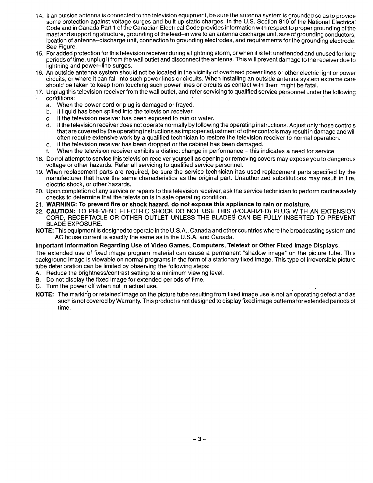
14.Ifanoutsideantennaisconnectedtothetelevisionequipment,besuretheantennasystemisgroundedsoastoprovide
someprotectionagainstvoltagesurgesandbuiltupstaticcharges.IntheU.S.Section810oftheNationalElectrical
CodeandinCanadaPartI oftheCanadianElectricalCodeprovidesinformationwithrespecttopropergroundingofthe
mastandsupportingstructure,groundingofthelead-inwiretoanantennadischargeunit,sizeofgroundingconductors,
locationofantenna-dischargeunit,connectiontogroundingelectrodes,andrequirementsforthegroundingelectrode.
SeeFigure.
15.Foraddedprotectionforthistelevisionreceiverduringalightningstorm,orwhenitisleftunattendedandunusedforlong
periodsoftime,unplugitfromthewalloutletanddisconnecttheantenna.Thiswillpreventdamagetothereceiverdueto
lightningandpower-linesurges.
16.Anoutsideantennasystemshouldnotbelocatedinthevicinityofoverheadpowerlinesorotherelectriclightorpower
circuits,orwhereitcanfallintosuchpowerlinesorcircuits.Wheninstallinganoutsideantennasystemextremecare
shouldbetakentokeepfromtouchingsuchpowerlinesorcircuitsascontactwiththemmightbefatal.
17.Unplugthistelevisionreceiverfromthewalloutlet,andreferservicingtoqualifiedservicepersonnelunderthefollowing
conditions:
a. Whenthepowercordorplugisdamagedorfrayed.
b. Ifliquidhasbeenspilledintothetelevisionreceiver.
c. Ifthetelevisionreceiverhasbeenexposedtorainorwater.
d. Ifthetelevisionreceiverdoesnotoperatenormallybyfollowingtheoperatinginstructions.Adjustonlythosecontrols
thatarecoveredbytheoperatinginstructionsasimproperadjustmentofothercontrolsmayresultindamageandwill
oftenrequireextensiveworkbyaqualifiedtechniciantorestorethetelevisionreceivertonormaloperation.
e. Ifthetelevisionreceiverhasbeendroppedorthecabinethasbeendamaged.
f. Whenthetelevisionreceiverexhibitsadistinctchangeinperformance- thisindicatesa needforservice.
18.Donotattempttoservicethistelevisionreceiveryourselfasopeningorremovingcoversmayexposeyoutodangerous
voltageorotherhazards.Referallservicingto qualifiedservicepersonnel.
19.Whenreplacementpartsarerequired,besuretheservicetechnicianhasusedreplacementpartsspecifiedbythe
manufacturerthathavethesamecharacteristicsastheoriginalpart.Unauthorizedsubstitutionsmayresultinfire,
electricshock,orotherhazards.
20.Uponcompletionofanyserviceorrepairstothistelevisionreceiver,asktheservicetechniciantoperformroutinesafety
checkstodeterminethatthetelevisionisinsafeoperatingcondition.
21.WARNING: To prevent fire or shock hazard, do not expose this appliance to rain or moisture.
22. CAUTION: TO PREVENT ELECTRIC SHOCK DO NOT USE THIS (POLARIZED) PLUG WITH AN EXTENSION
CORD, RECEPTACLE OR OTHER OUTLET UNLESS THE BLADES CAN BE FULLY INSERTED TO PREVENT
BLADE EXPOSURE.
NOTE: This equipment isdesigned tooperate inthe U.S.A., Canada and other countries where the broadcasting system and
AC house current is exactly the same as in the U.S.A. and Canada.
Important Information Regarding Use of Video Games, Computers, Teletext or Other Fixed Image Displays.
The extended use of fixed image program material can cause a permanent "shadow image" on the picture tube. This
background image is viewable on normal programs in the form of a stationary fixed image. This type of irreversible picture
tube deterioration can be limited by observing the following steps:
A. Reduce the brightness/contrast setting to a minimum viewing level.
B. Do not display the fixed image for extended periods of time.
C. Turn the power off when not in actual use.
NOTE: The markin'g or retained image on the picture tube resultingfrom fixed image use is not an operating defect and as
such isnot covered byWarranty. This productis notdesigned to displayfixed image patterns for extended periods of
time.
3
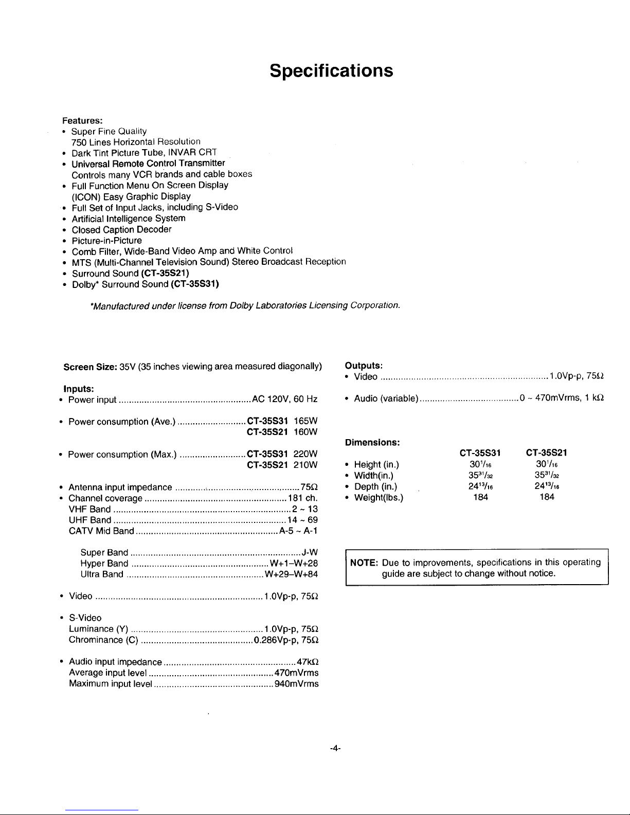
Specifications
Features:
• Super Fine Quality
750 Lines Horizontal Resolution
• Dark Tint Picture Tube, INVAR CR-r
• Universal Remote Control Transmitter
Controls many VCR brands and cable boxes
• Full Function Menu On Screen Display
(ICON) Easy Graphic Display
• Full Set of Input Jacks, including S-Video
• Artificial Intelligence System
• Closed Caption Decoder
• Picture-in-Picture
• Comb Filter, Wide-Band Video Amp and White Control
• MTS (Multi-Channel Television Sound) Stereo Broadcast Reception
• Surround Sound (CT-35S21)
• Dolby* Surround Sound (CT-35S31)
*Manufactured under license from Dolby Laboratories Licensing Corporation.
Screen Size: 35V (35 inches viewing area measured diagonally)
Inputs:
• Power input .................................................... AC 120V, 60 Hz
• Power consumption (Ave.) ........................... CT-35S31 165W
CT-35S21 160W
• Power consumption (Max.) .......................... CT-35S31 220W
CT-35S21 210W
Antenna input impedance .................................................. 75_
Channel coverage ........................................................ 181 ch.
VHF Band ...................................................................... 2 ~ 13
UHF Band .................................................................... 14 ~ 69
CATV Mid Band ........................................................ A-5 ~ A-1
Super Band ................................................................... J-W
Hyper Band ...................................................... W+1-W+28
Ultra Band ...................................................... W+29-W+84
• Video .................................................................. 1.0Vp-p, 75_
• S-Video
Luminance (Y) .................................................... 1.0Vp-p, 75£
Chrominance (C) ............................................ 0.286Vp-p, 75Q
• Audio input impedance .................................................... 47k£
Average input level ................................................. 470mVrms
Maximum input level ............................................... 940mVrms
Outputs:
• Video .................................................................. 1.0Vp-p, 75_,2
• Audio (variable) ....................................... 0 - 470mVrms, 1 kQ
Dimensions:
CT-35S31 CT-35S21
• Height (in.) 301/16 301/16
• Width(in.) 3531/_ 3531/_
• Depth (in.) 2413/16 2413/16
• Weight(Ibs.) 184 184
I
NOTE: Due to improvements, specifications in this operating I
guide are subject to change without notice.
I
-4-
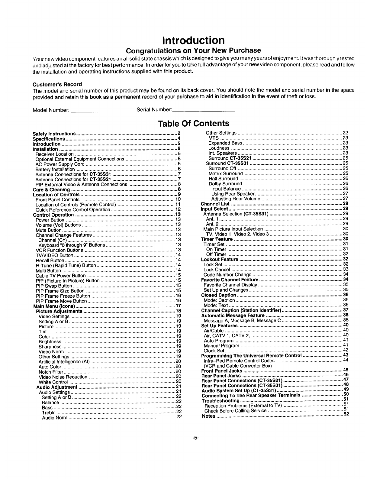
Introduction
Congratulations on Your New Purchase
Your new video component features an all solid state chassis which is designed to give you many years of enjoyment. It was thoroughly tested
and adjusted at the factory for best performance. In order for you to take full advantage of your new video component, please read and follow
the installation and operating instructions supplied with this product.
Customer's Record
The model and serial number of this product may be found on its back cover. You should note the model and serial number in the space
provided and retain this book as a permanent record of your pui'chase to aid in identification in the event of theft or loss.
Model Number:
Serial Number:
Table Of Contents
Safety Instructions ............................................................................ 2
Specifications .................................................................................... 4
Introduction ....................................................................................... 5
Installation ......................................................................................... 6
Receiver Location ............................................................................. 6
Optional External Equipment Connections ....................................... 6
AC Power Supply Cord ..................................................................... 6
Battery Installation ............................................................................ 6
Antenna Connections for CT-35S31 ................................................. 7
Antenna Connections for CT-35S21 ................................................. 7
PIP External Video & Antenna Connections ..................................... 8
Care & Cleaning ................................................................................ 8
Location of Controls ......................................................................... 9
Front Panel Controls ....................................................................... 10
Location of Controls (Remote Control) ........................................... 11
Quick Reference Control Operation ................................................ 12
Control Operation ........................................................................... 13
Power Button .................................................................................. 13
Volume (Vol) Buttons ...................................................................... 13
Mute Button ..................................................................................... 13
Channel Change Features .............................................................. 13
Channel (Ch) ................................................................................. 13
Keyboard "0 through 9" Buttons .................................................... 13
VCR Function Buttons .................................................................... 13
TV/VIDEO Button ............................................................................ 14
Recall Button ................................................................................... 14
R-Tune (Rapid Tune) Button ........................................................... 14
Multi Button ..................................................................................... 14
Cable TV Power Button .................................................................. 15
PIP (Picture In Picture) Button ........................................................ 15
PIP Swap Button ............................................................................. 15
PIP Frame Size Button ................................................................... 15
PIP Frame Freeze Button ............................................................... 16
PIP Frame Move Button .................................................................. 16
Main Menu (Icons) ........................................................................... 17
Picture Adjustments ..................................................................... 18
Video Settings ............................................................................... 19
Setting A or B ................................................................................ 19
Picture ........................................................................................... 19
Tint ................................................................................................ 19
Color ............................................................................................. 19
Brightness ..................................................................................... 19
Sharpness ..................................................................................... 19
Video Norm ................................................................................... 19
Other Settings ............................................................................... 19
Artificial Intelligence (AI) ............................................................... 20
Auto Color ..................................................................................... 20
Notch Filter .................................................................................... 20
Video Noise Reduction ................................................................. 20
White Control ................................................................................ 20
Audio Adjustment ......................................................................... 21
Audio Settings ............................................................................... 21
Setting A or B .............................................................................. 22
Balance ....................................................................................... 22
Bass ............................................................................................ 22
Treble .......................................................................................... 22
Audio Norm ................................................................................. 22
Other Settings ............................................................................... 22
MTS ............................................................................................ 23
Expanded Bass ........................................................................... 23
Loudness .................................................................................... 23
Int. Speakers ............................................................................... 23
Surround CT-35S21 .................................................................... 25
Surround CT-35S31 ...................................................................... 25
Surround Off ............................................................................... 25
Matrix Surround .......................................................................... 25
Hall Surround .............................................................................. 26
Dolby Surround ........................................................................... 26
Input Balance ............................................................................ 26
Using Rear Speaker .................................................................. 27
Adjusting Rear Volume ............................................................. 27
Channel List .................................................................................... 28
Input Select ...................................................................................... 29
Antenna Selection (CT-35S31) ....................................................... 29
Ant. 1............................................................................................. 29
Ant. 2 ............................................................................................. 29
Main Picture Input Selection ........................................................... 30
TV, Video 1, Video 2, Video 3 ....................................................... 30
Timer Feature .................................................................................. 30
Timer Set ........................................................................................ 31
On Timer ....................................................................................... 31
Off Timer ....................................................................................... 32
Lockout Feature .............................................................................. 32
Lock Set .......................................................................................... 32
Lock Cancel .................................................................................... 33
Code Number Change .................................................................... 34
Favorite Channel Feature ............................................................... 34
Favorite Channel Display ................................................................ 35
Set Up and Changes ....................................................................... 35
Closed Caption ................................................................................ 36
Mode: Caption ................................................................................. 36
Mode: Text ...................................................................................... 36
Channel Caption (Station Identifier) .............................................. 37
Automatic Message Feature .......................................................... 38
Message A, Message B, Message C .............................................. 38
Set Up Features ............................................................................... 40
Air/Cable ......................................................................................... 40
Air, CATV 1, CATV 2...................................................................... 40
Auto Program .................................................................................. 41
Manual Program ............................................................................. 41
Clock Set ......................................................................................... 42
Programming The Universal Remote Control .............................. 43
Infra-Red Remote Control Codes ................................................... 44
(VCR and Cable Converter Box)
Front Panel Jacks ........................................................................... 45
Rear Panel Jacks ............................................................................ 46
Rear Panel Connections (CT-35S21) ............................................. 47
Rear Panel Connections (CT-35S31) ............................................. 48
Audio System Set Up (CT-35S31) .................................................. 49
Connecting To The Rear Speaker Terminals ............................... 50
Troubleshooting .............................................................................. 5 _
Reception Problems (External to TV) .............................................
Check Before Calling Service ......................................................... 51
Notes ................................................................................................ 52
-5-
Installation
Receiver Location
Locate for comfortable viewing. Avoid placing where sunlight or other bright light (including reflections) will fall on the screen. Adequate
ventilation is essential to prevent internal component failure. Keep away from areas of excessive heat or moisture. Do not position magnetic
equipment (motors, fans, other speakers, etc.) nearby.
Optional External Equipment Connections
The Video/Audio connections between components can be made with shielded video and audio cables. For best performance, video cables
should utilize 75 ohm coaxial shielded wire. Cables are available from your dealer or electronic supply house. Before you purchase any
cables, be sure you know what type of output and input connectors your various components require. Also determine the length of cable
you'll need. "
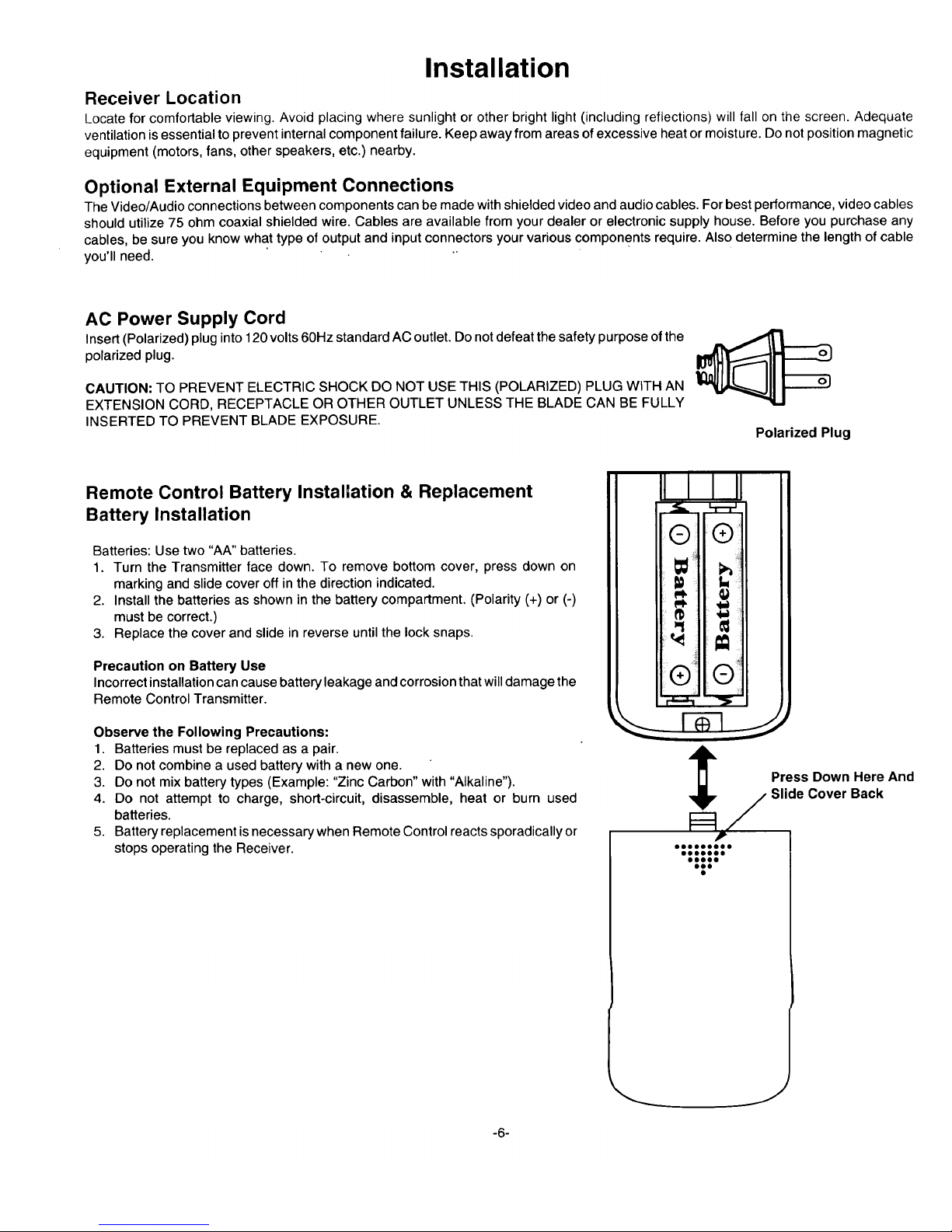
AC Power Supply Cord
Insert (Polarized) plug into 120 volts60Hz standard AC outlet. Do notdefeat the safety purpose ofthe A __,-.
polarized plug.
CAUTION: TO PREVENT ELECTRIC SHOCK DO NOT USE THIS (POLARIZED) PLUG WITH AN
EXTENSION CORD, RECEPTACLE OR OTHER OUTLET UNLESS THE BLADE CAN BE FULLY
INSERTED TO PREVENT BLADE EXPOSURE.
Polarized Plug
Remote Control Battery Installation & Replacement
Battery Installation
Batteries: Use two "AA" batteries.
1. Turn the Transmitter face down. To remove bottom cover, press down on
marking and slide cover off in the direction indicated.
2. Install the batteries as shown in the battery compartment. (Polarity (+) or (-)
must be correct.)
3. Replace the cover and slide in reverse until the lock snaps.
Precaution on Battery Use
Incorrect installation can cause battery leakage and corrosion that willdamage the
Remote Control Transmitter.
Observe the Following Precautions:
1. Batteries must be replaced as a pair.
2. Do not combine a used battery with a new one.
3. Do not mix battery types (Example: "Zinc Carbon" with "Alkaline").
4. Do not attempt to charge, short-circuit, disassemble, heat or burn used
batteries.
5. Battery replacement isnecessary when Remote Control reacts sporadically or
stops operating the Receiver.
!/®
"'iiii""
Press Down Here And
Slide Cover Back
J
-6-
Antenna Connections
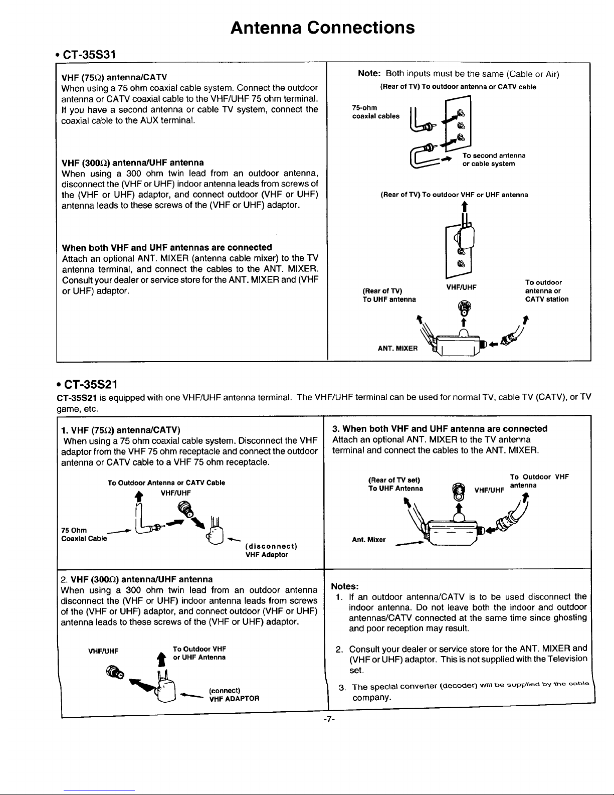
• CT-35S31
VHF (75_) antennaJCATV
When using a 75 ohm coaxial cable system. Connect the outdoor
antenna or CATV coaxial cable to the VHF/UHF 75 ohm terminal.
If you have a second antenna or cable TV system, connect the
coaxial cable to the AUX terminal.
VHF (300_) antenna/UHF antenna
When using a 300 ohm twin lead from an outdoor antenna,
disconnect the (VHF or UHF) indoor antenna leads from screws of
the (VHF or UHF) adaptor, and connect outdoor (VHF or UHF)
antenna leads to these screws of the (VHF or UHF) adaptor.
When both VHF and UHF antennas are connected
Attach an optional ANT. MIXER (antenna cable mixer)to the TV
antennaterminal,and connectthe cables to the ANT. MIXER.
Consultyourdealerorservicestorefor theANT. MIXER and(VHF
or UHF) adaptor.
Note: Both inputs must be the same (Cable or Air)
(Rear of TV) To outdoor antenna or CATV cable
75-ohm L_
coaxial cables
'_p. To second antenna
or cable system
(Rear of TV) To outdoor VHF or UHF antenna
t
(Rear of TV) VHF/UHF
To UHF antenna
ANT..,XE,
To outdoor
antenna or
CATV station
• CT-35S21
CT-35S21 is equipped with one VHF/UHF antenna terminal. The VHF/UHF terminal can be used for normal TV, cable TV (CATV), or TV
lame, etc.
1. VHF (75_) antenna/CATV)
When using a 75 ohm coaxial cable system. Disconnect the VHF
adaptor from the VHF 75 ohm receptacle and connect the outdoor
antenna or CATV cable to a VHF 75 ohm receptacle.
To Outdoor Antenna or CATV Cable
t VHF/UHF
75Ohm ......-._ ___
Coaxial Cable
(disconnect)
VHF Adaptor
2. VHF (300_) antenna/UHF antenna
When using a 300 ohm twin lead from an outdoor antenna
disconnect the (VHF or UHF) indoor antenna leads from screws
of the (VHF or UHF) adaptor, and connect outdoor (VHF or UHF)
antenna leads to these screws of the (VHF or UHF) adaptor.
VHF/UHF To Outdoor VHF
or UHF Antenna
_) '_ (connect)
VHF ADAPTOR
3. When both VHF and UHF antenna are connected
Attach an optional ANT. MIXER to the TV antenna
terminal and connect the cables to the ANT. MIXER.
(Rear of TV set) To Outdoor VHF
To UHF Antenna _1_ VHF/UHF antenna
Ant. Mixer
Notes:
1. If an outdoor antenna/CATV is to be used disconnect the
2,
indoor antenna. Do not leave both the indoor and outdoor
antennas/CATV connected at the same time since ghosting
and poor reception may result.
Consult your dealer or service store for the ANT. MIXER and
(VHF or UHF) adaptor. This is not supplied with the Television
set.
]-he s_)ec_l.I convertor _3_co_3_r) w_\\ be supp_e_ b_t .,he cable
company.
3.
-7-
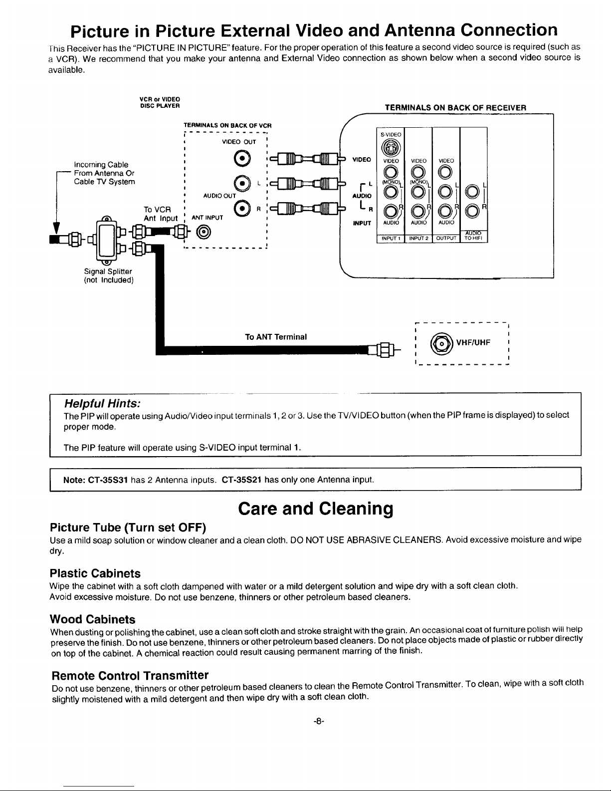
Picture in Picture External Video and Antenna Connection
this Receiver has the "PICTURE IN PICTURE" feature. For the proper operation ofthis feature a second video source is required (such as
a VCR). We recommend that you make your antenna and External Video connection as shown below when a second video source is
available.
VCR or VIDEO
DISC PLAYER
Incoming Cable
From Antenna Or
Cable TV System
TOVCR
TERMINALS ON BACK OF VCR
VIDEO OUT
AUDIO OUT
!
Ant Input ANTINPUT
....... ..-..
Signal Splitter
(not Included)
To ANT Terminal
TERMINALS ON BACK OF RECEIVER
F
S-VIDEO
@
INPUT AUDIO
INPUT 1
VIDEO VIDEO
©
oi
AUDIO AUDIO
INPUT 2LOUTPUT TO HIFI
I
I
I
I
I
VHF/UHF
I
I
I
I
I
Helpful Hints:
The PIP willoperate using Audio/Video input terminals 1,2 or 3. Use the TV/VIDEO button (when the PIP frame is displayed) to select
proper mode.
The PIP feature will operate using S-VIDEO input terminal 1.
Note: CT-35S31 has 2 Antenna inputs. 0T-35S21 has only one Antenna input.
Care and Cleaning
Picture Tube (Turn set OFF)
Use a mild soap solution or window cleaner and a clean cloth. DO NOT USE ABRASIVE CLEANERS. Avoid excessive moisture and wipe
dry.
Plastic Cabinets
Wipe the cabinet with a soft cloth dampened with water or a mild detergent solution and wipe dry with a soft clean cloth.
Avoid excessive moisture. Do not use benzene, thinners or other petroleum based cleaners.
Wood Cabinets
When dusting or polishingthe cabinet, use a clean soft cloth and stroke straight with the grain. An occasional coat offurniture polishwillhelp
preserve the finish. Do not use benzene, thinners or other petroleum based cleaners. Do not place objects made ofplastic or rubber directly
on top of the cabinet. A chemical reaction could result causing permanent marring of the finish.
Remote Control Transmitter
Do not use benzene, thinners or other petroleum based cleaners to clean the Remote Control Transmitter. To clean, wipe with a soft cloth
slightly moistened with a mild detergent and then wipe drywith a soft clean cloth.
-8-
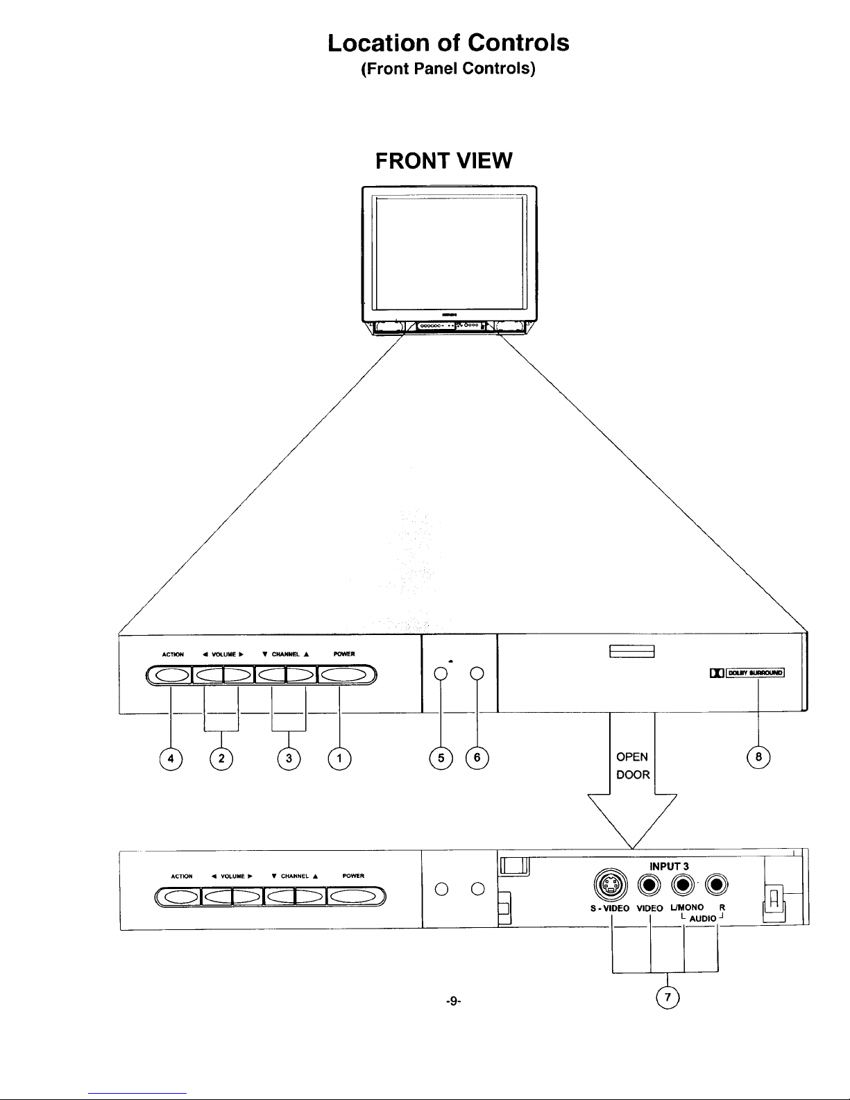
Location of Controls
(Front Panel Controls)
FRONT VIEW
-9-
ACTION • VOLUME • • CHANNEL • POWER
©
OPEN
INPUT 3
@®÷-®
S-VIDEO VIDEO UMONO R
Front Panel Controls
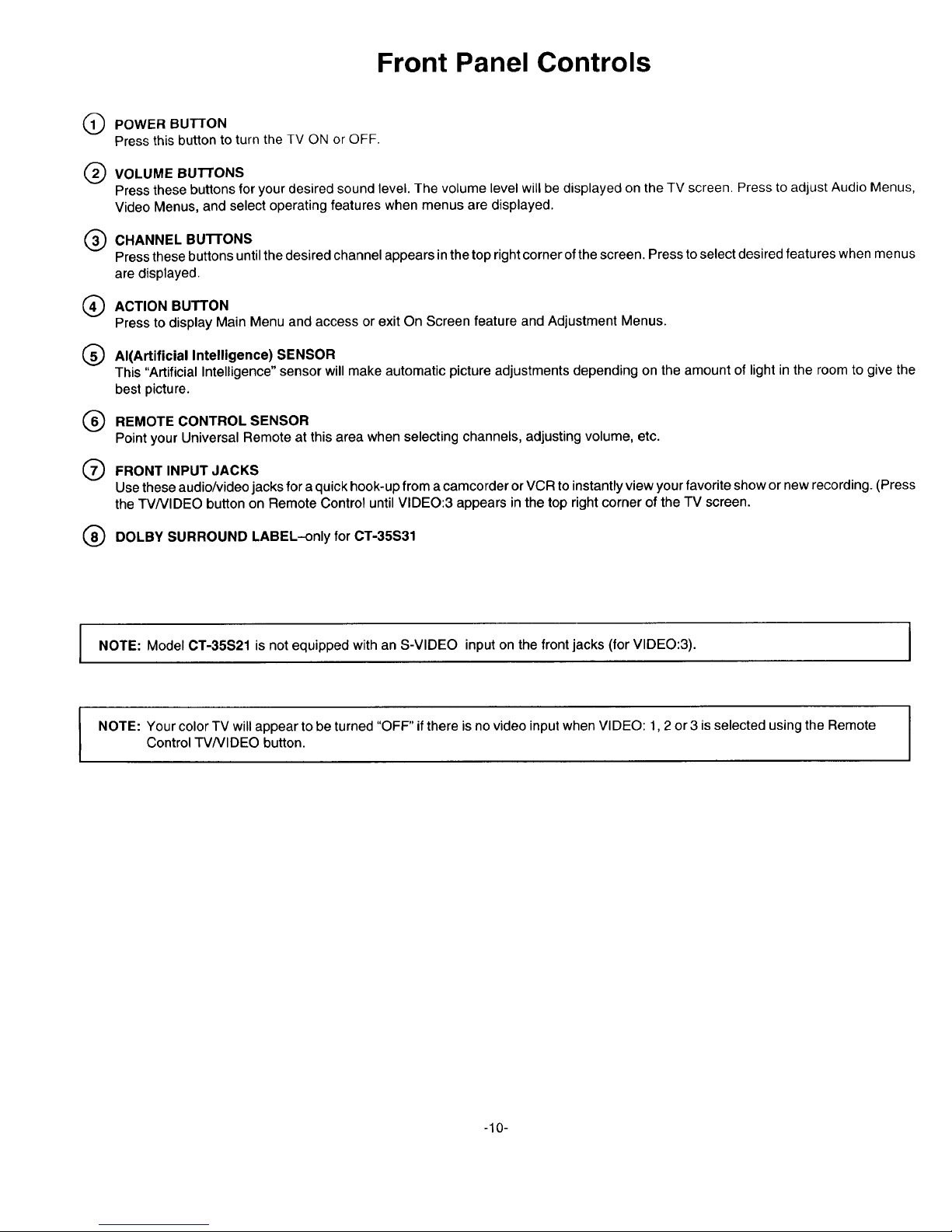
Q POWER BUTTON
Press this button to turn the TV ON or OFF.
Q VOLUME BUTTONS
Press these buttons for your desired sound level. The volume level will be displayed on the TV screen. Press to adjust Audio Menus,
Video Menus, and select operating features when menus are displayed.
Q HANNEL BUTTONS
Press these buttons until the desired channel appears in the top right corner of the screen. Press to select desired features when menus
are displayed.
ACTION BUTTON
Press to display Main Menu and access or exit On Screen feature and Adjustment Menus.
Q Al(Artificial Intelligence)
SENSOR
This "Artificial Intelligence" sensor will make automatic picture adjustments depending on the amount of light in the room to give the
best picture.
(_ CONTROL SENSOR
REMOTE
Point your Universal Remote at this area when selecting channels, adjusting volume, etc.
Q FRONT INPUT JACKS
Use these audio/video jacks for a quick hook-up from a camcorder or VCR toinstantly view your favorite show or new recording. (Press
the TVNIDEO button on Remote Control until VIDEO:3 appears in the top right corner of the TV screen.
(_ DOLBY SURROUND LABEL-only for CT-35S31
NOTE: Model CT-35S21 is not equipped with an S-VIDEO input on the front jacks (for VIDEO:3).
NOTE: Your color TV will appear to be turned "OFF" ifthere is no video inputwhen VIDEO: 1,2 or 3 isselected using the Remote
Control-I'VNIDEO button.
-10-
Location of Controls (RemoteControl)
®
POWER
O MULTI
CD ®
®
®
®
@
®
®
ACTION
® ® ®
® ® ®
_@ @ @
o_c,,,©L@j,_F.t_
- -VC-'-R CABLE
POWER RECORD _._
MOVE SIZE PIP
I TV/VCR STOP PAUSE
i_-i i--z-_ i---_
[ FREEZE SWAP
I__ -- -- VCR CHANNEL
®
®
®
®
@
@
©
\ ®
®
J
-11-
Location of Controls (Remote Control)
Quick Reference Control Operation
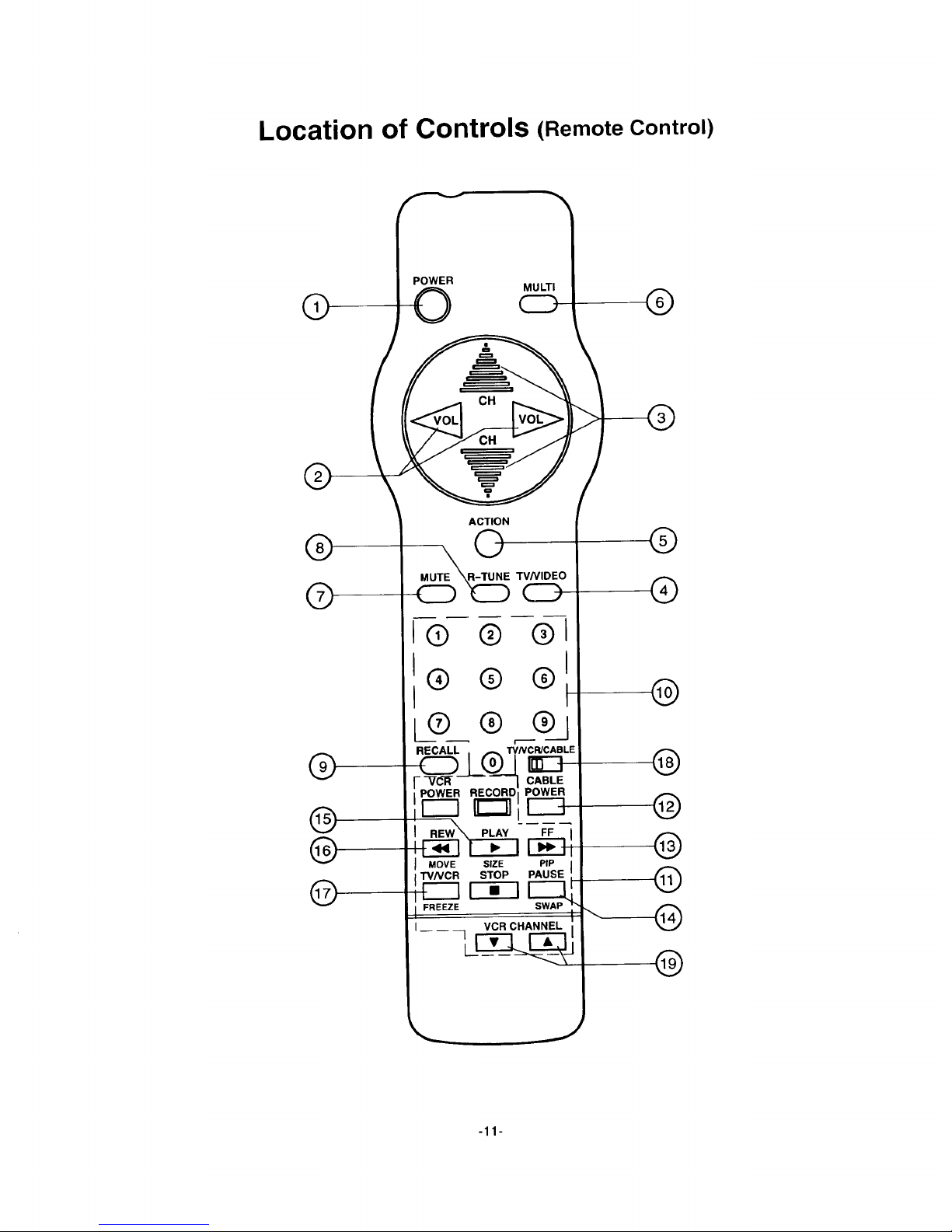
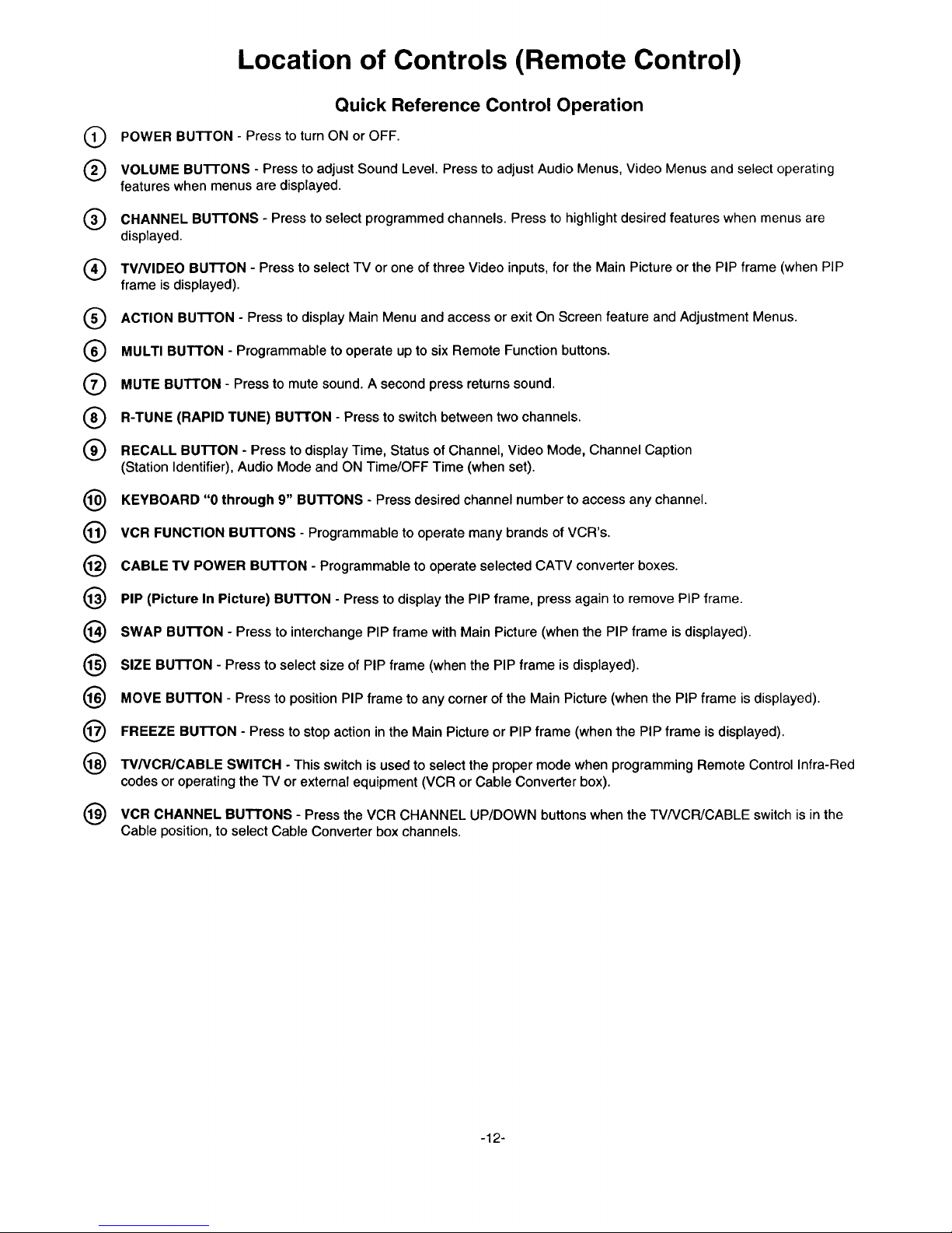
Q POWER BUTTON - Press to turn ON or OFF.
Q VOLUME Bu'n'ONS - Press to adjust Sound Level. Press to adjust Audio Menus, Video Menus and select operating
features when menus are displayed.
Q CHANNEL BUTTONS - Press to select programmed channels. Press to highlight desired features when menus are
displayed.
Q TV/VIDEO BUTTON - Press to select TV or one of three Video inputs, for the Main Picture or the PIP frame (when PIP
frame is displayed).
Q ACTION BUTTON - Press to display Main Menu and access or exit On Screen feature and Adjustment Menus.
Q MULTI BUTTON - Programmable to operate up to six Remote Function buttons.
Q MUTE BUTTON - Press to mute sound. A second press returns sound.
(_ R-TUNE (RAPID TUNE) BUTTON - Press to switch between two channels.
(_) RECALL BUTTON - Press to display Time, Status of Channel, Video Mode, Channel Caption
(Station Identifier), Audio Mode and ON Time/OFF Time (when set).
(_ KEYBOARD "0 through 9" Bu'n'ONS - Press desired channel number to access any channel.
VCR FUNCTION BuI-rONS - Programmable to operate many brands of VCR's.
CABLE TV POWER BUTTON - Programmable to operate selected CATV converter boxes.
PIP (Picture In Picture) BUTTON - Press to display the PIP frame, press again to remove PIP frame.
(_) SWAP Bu'n'ON - Press to interchange PIP frame with Main Picture (when the PIP frame is displayed).
(_) SIZE BUTTON - Press to select size of PIP frame (when the PIP frame is displayed).
(_ MOVE BUTTON - Press to position PIP frame to any corner of the Main Picture (when the PIP frame is displayed).
FREEZE BUTTON - Press to stop action in the Main Picture or PIP frame (when the PIP frame is displayed).
(_) TV/VCPJCABLE SWITCH - This switch is used to select the proper mode when programming Remote Control Infra-Red
codes or operating the "IV or external equipment (VCR or Cable Converter box).
(_ VCR CHANNEL BUTTONS - Press the VCR CHANNEL UP/DOWN buttons when the TV/VCR/CABLE switch is in the
Cable position, to select Cable Converter box channels.
-12-

Control Operation
POWER--Press the POWER button to turn ON. Press again to
turn OFF.
POWER
VOLUME-- Press the VOLUME (VOL) LEFT or RIGHT button
fordesired listeninglevel (when On Screen Menus are not displayed).
Located On Remote Control
Increases
Volume Level
J
Decreases
Volume Level
MUTE-- Press the MUTE button to quickly reduce sound level
(Mute will appear on screen). Press again to restore sound.
MUTE
Helpful Hints:
Helpful information willdisplay On Screen momentarily when
Receiver is first turned ON and when the channel is changed.
When using keyboard entry for channels 10,11 and 12 inthe
CABLE mode there is a slight delay before channel change
because of the capability of tuning cable channels 100 to 125.
If you do not receive channels above 13, confirm the type of
signal at ANT Input (TV or Cable) and set the TV or Cable
Tuning Mode accordingly. (Refer to Set Up Feature,
Air/Cable Selection)
NOTE: ANT Input TV is the same as ANT Input "AIR".
CHANNEL CHANGE -(Twooptions)
Option 1.
Press the CHANNEL (CH) UP or DOWN button to sequentially
scan through programmed channels (when On Screen Menus are
not displayed).
Located On Remote Control
Selects Next
Higher Channel
Selects Next
Lower Channel
Option 2.
Press two digits on keyboard (Example press 0, then 5 for
channel 05). Forchannels over 99, pressthree digits onkeyboard.
q
I® ® G I
®1
I I
I® ®1
VCR FUNCTION BUTTONS--The VCR FUNCTION
buttons have been designed to operate numerous brands of VCRs.
The infra-red code must be obtained prior to use. (Please refer to
Programming the Universal Remote for programming instructions.)
I
-13-
NOTE: The TVNCR/CABLE switch (located on Remote) must
be in the VCR position (Center).
"FV/VCR/CABLE
VCR ]
POWER_RIND,
L_
REW PLAY FF
MOVE SIZE PIP
T'V/VCR STOP PAUSE
FREEZE SWAP
VCR CHANNEL
.... 1
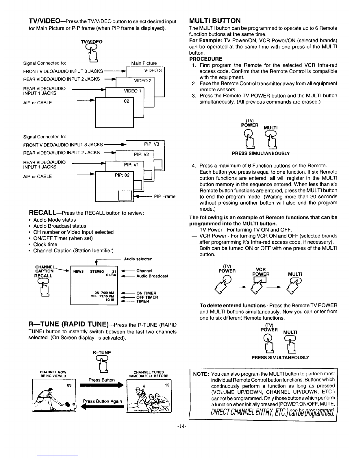
TWtVlDEO--Press the TV/VlDEO button to select desired input
for Main Picture or PIP frame (when PIP frame is displayed).
Signal Connected to:
FRONT VIDEO/AUDIO INPUT 3 JACKS
REARVIDEO/AUDIOINPUT 2JACKS _1
"1
REARVIDEO/AUDIO
INPUT 1JACKS
AIRor CABLE _
1
MainPicture
_-i VIDEO3
VIDEO2
V'°E°'I 1__1
Signal Connected to:
FRONTVIDEO/AUDIO INPUT3 JACKS =! PIP: V3
REARV,DEO/AUD'O'NPUT2JACKS--'1 = P,PV2[--I
REARVDEO/AUDO r " -- "-'
INPUT 1JACKS "t-I PIP:Vl L-._ _l-J
AIRorCABLE fi PIP:02 h_.J
/ PIPFrame
RECALL--Press the RECALL button to review:
• Audio Mode status
• Audio Broadcast status
• CH number or Video Input selected
• ON/OFF Timer (when set)
• Clock time
• Channel Caption (Station Identifier)
Audio selected
t
CHANNEL_ I II
CAPTION _ NEWS STEREO 31 I _ Channel
RECALL ST/SA <1_ Audio Broadcast
(_ ON 7:00AM I _I-_ ON TIMER
OFF 11:15PM I <I_ OFF TIMER
10:15 ] _TIMER
R--TUNE (RAPID TUNE)--Press the R-TUNE (RAPID
TUNE) button to instantly switch between the last two channels
selected (On Screen display is activated).
R-TUNE
CHANNEL NOW _ CHANNEL TUNED
BEING VIEWED IMMEDIATELY BEFORE
03 _
//_ Press Button Again
%-tb. .,
-14-
MULTI BUTTON
The MULTI button can be programmed to operate up to 6 Remote
function buttons at the same time.
For Example: TV Power/ON, VCR Power/ON (selected brands)
can be operated at the same time with one press of the MULTI
button.
PROCEDURE
1. First program the Remote for the selected VCR Infra-red
access code. Confirm that the Remote Control is compatible
with the equipment.
2, Face the Remote Control transmitter away from all equipment
remote sensors.
3. Press the Remote TV POWER button and the MULTI button
simultaneously, (All previous commands are erased.)
(TV)
POWER
MULTI
PRESS SIMULTANEOUSLY
4. Press a maximum of 6 Function buttons on the Remote.
Each button you press is equal to one function. If six Remote
button functions are entered, all will register in the MULTI
button memory in the sequence entered. When less than six
Remote button functions are entered, press the MULTI button
to end the program mode. (Waiting more than 30 seconds
without pressing another button will also end the program
mode.)
The following is an example of Remote functions that can be
programmed into the MULTI button.
-- TV Power - For turning TV ON and OFF.
-- VCR Power - For turning VCR ON and OFF (selected brands
after programming it's Infra-red access code, if necessary).
Both can be turned ON or OFF with one press of the MULTI
button.
frv)
POWER VCR
POWER MULTI
To delete entered functions - Press the Remote TV POWER
and MULTI buttons simultaneously. Now you can enter from
one to six different Remote functions.
(TV)
POWER
MULTI
PRESS SIMULTANEOUSLY
NOTE: You can also program the MULTI button to perform most
individual Remote Control button functions. Buttons which
continuously perform a function as long as pressed
(VOLUME UP/DOWN, CHANNEL UP/DOWN, ETC.)
cannot be programmed. Only those buttons which perform
afunction when initially pressed (POWER ON/OFF, MUTE,
DIRECTCHANNELENTRY,ETC.)O TfltJ##[Ogfgillfll##,
I
CABLE (TV) POWER BUTTON--The CABLEPOWER
button on the Remote Control has been designed to operate
selected brands of Cable Television Converter boxes. The proper
cable television converter infra-red code must be obtained prior to
use. (Please refer to Programming the Universal Remote for
programming instructions.) The Remote Control TV/VCR/CABLE
switch should be in the CABLE position.
I NOTE: The VCR CHANNEL UP and DOWN buttons on the
Remote may be used for selecting Cable Converter box
channels.
CABLE
POWER
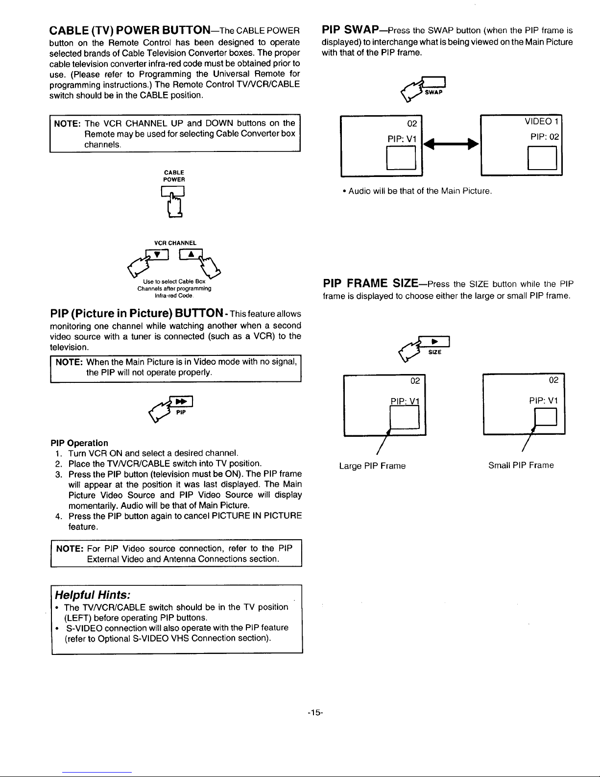
PIP SWAP--Press the SWAP button (when the PIP frame is
displayed) to interchange what is being viewed on the Main Picture
with that of the PIP frame.
O2
PIP: V1
• Audio will be that of the Main Picture.
VIDEO 1
PIP: 02
VCR CHANNEL
Use to select Cable Box
Channels after programming
Infra-red Code,
PIP (Picture in Picture) BUTTON- This feature allows
monitoring one channel while watching another when a second
video source with a tuner is connected (such as a VCR) to the
television.
NOTE: When the Main Picture is in Video mode with no signal, I
the PIP will not operate properly.
I
PIP Operation
1. Turn VCR ON and select a desired channel.
2. Place the TVNCR/CABLE switch into TV position.
3. Press the PIP button (television must be ON). The PIP frame
will appear at the position it was last displayed. The Main
Picture Video Source and PIP Video Source will display
momentarily. Audio will be that of Main Picture.
4. Press the PIP button again to cancel PICTURE IN PICTURE
feature.
NOTE: For PIP Video source connection, refer to the PIPExternal Video and Antenna Connections section.
PIP FRAME SiZE--Press the SIZE button while the PIP
frame is displayed to choose either the large or small PIP frame.
I
PIP: V1
2?,
/
Large PIP Frame
02I
PIP: V1
P
/
Small PIP Frame
Helpful Hints:
• The TV/VCR/CABLE switch should be in the TV position
(LEFT) before operating PIP buttons.
• S-VIDEO connection will also operate with the PIP feature
(refer to Optional S-VIDEO VHS Connection section).
-15-
PIP FREEZE FRAME FEATURE-Press the FREEZE
button to stop action in the Main Picture or PIP frame.
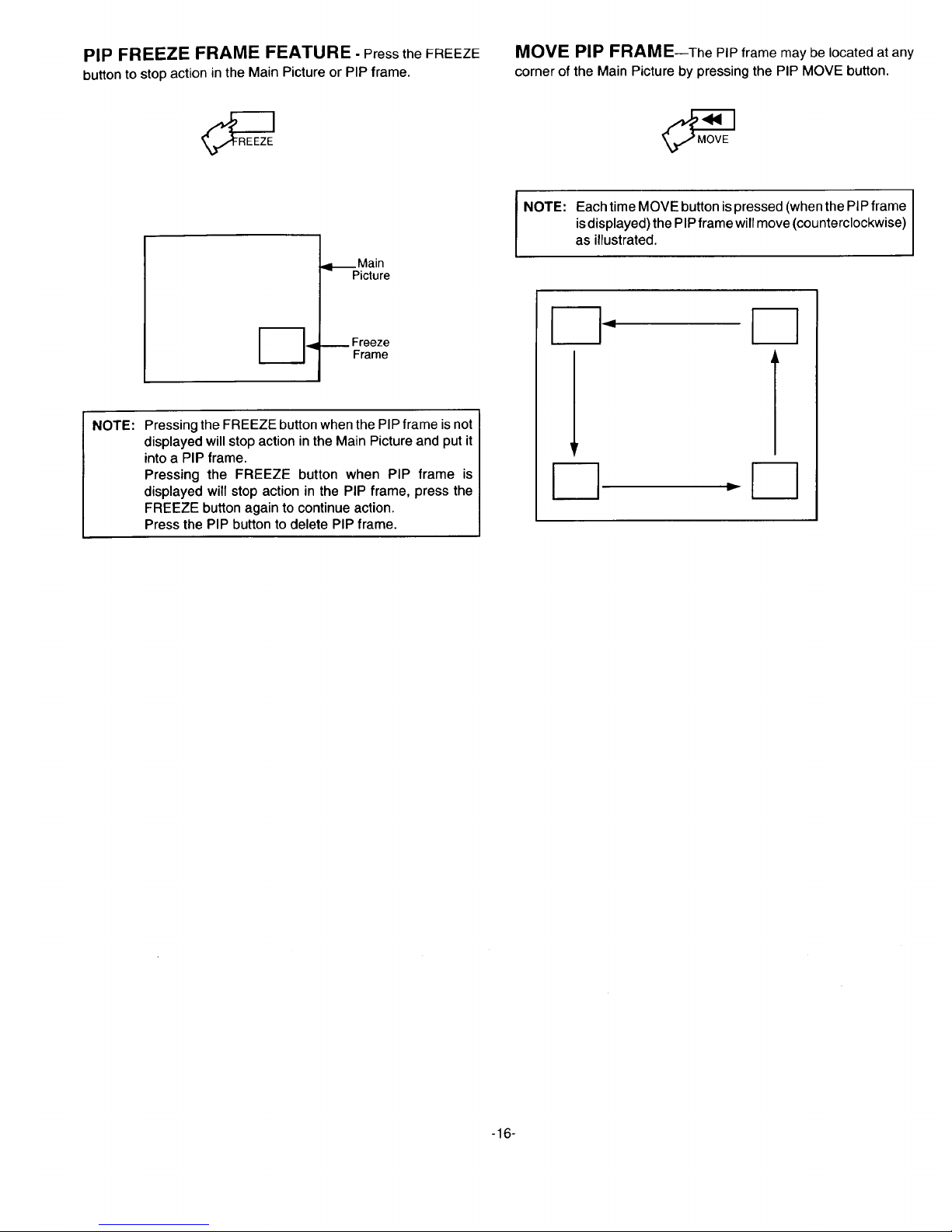
MOVE PIP FRAME--The PIP frame may be located at any
corner of the Main Picture by pressing the PIP MOVE button.
NOTE:
,il_Main
Picture
-.9 _ Frame
Pressing the FREEZE button when the PIP frame is not
displayed will stop action in the Main Picture and put it
into a PIP frame.
Pressing the FREEZE button when PIP frame is
displayed will stop action in the PIP frame, press the
FREEZE button again to continue action.
Press the PIP button to delete PIP frame.
NOTE:
Each time MOVE button is pressed (when the PIP frame
isdisplayed) the PIP frame will move (counterclockwise)
as illustrated.
-16-
 Loading...