

Page 1
Color Television
Operating Instructions
Read these instructions completely before operating this set.
Contents subject to change without notice or obligation.
Copyright 1996 by Matsushita Electric Corporation of America.
All rights reserved. Unauthorized copying and distribution is a violation of law.
CT-35G31
Printed in Canada
TQB2AA0073
Page 2
Safety Instructions
WARNING
RISK OF ELECTRIC SHOCK
00 NOT OPEN
WARNING: To reduce the risk of electric shock do not remove cover or back. No
user-serviceable parts inside. Refer servicing to qualified service personnel.
The lightning flash with ar
row-head within a triangle
is intended to tel) the user
that parts inside the product
are a risk of electric shock to
persons.
A
The exclamation point within
a triangle is intended to tel)
the user that important oper
ating and servicing instruc
tions are in the papers with
the appliance.
Note to CATV System Installer: This reminder is provided to call the CATV system installer’s attention to Article
820-40 of the NEC that provides guidelines for proper grounding and, in particular, specifies that the cable ground shall be
connected to the grounding system of the building, as close to the point of cable entry as practical.
Safety Instructions for Television Receivers
1. Read and apply the operating instructions provided with your television receiver.
2. Read all of the instructions given here and retain them for later use.
3. Unplug this television receiver from the wall outlet before cleaning. Do not use liquid or aerosol cleaners. Use a damp
cloth for cleaning.
4. Do not use attachments not recommended by the television receiver manufacturer as they may cause hazards.
5. Do not use this television receiver near water. For example: Avoid placing It near a bathtub, washbowl, kitchen sink, or
laundry tub, in a wet basement, or near a swimming pool, etc.
6. Do not place this television receiver on an unstable cart, stand, or table. The television receiver may fall, causing serious
injury to a child or adult, and serious damage to the appliance. Use only with a cart or stand recommended by the
manufacturer, or sold with the television receiver. Wall or shelf mounting should follow the manufacturer’s instructions,
and should use a mounting kit approved by the manufacturer.
6A. An appliance and cart combination should be moved with care. Quick stops, excessive force, and
uneven surfaces may cause the appliance and cart combination to overturn.
7. Slots and openings in the cabinet and the back or bottom are provided for ventilation, and to insure
reliable operation of the television receiver and to protect it from overheating. These openings must not be blocked or
covered. The openings should never be blocked by placing the television receiver on a bed, sofa, rug or other similar
surface. This television receiver should never be placed near or over a radiator or heat register. This television receiver
should not be placed in a built-in installation such as a bookcase unless proper ventilation is provided.
8. Operate only from the type of power source indicated on the marking label. If you are not sure of the type of power
supplied to your home consult your television dealer or local power company. For television receivers designed to
operate from battery power, refer to the operating instructions.
9. This television receiver is equipped with a polarized alternating^urrent line plug (a plug having one blade wider than the
other). This plug will fit into the power outlet only one way. This is a safety feature. If you are unable to insert the plug
fully into the outlet, try reversing the plug. If
the plug should stilt fail to fit, contact your
electrician to replace your obsolete outlet. Do
not defeat the safety purpose of the polarized
plug.
10. Do not allow anything to rest on the power
cord. Do not locate this television receiver
where the cord wilt be abused by persons
walking on it.
11. Follow all warnings and instructions marked
on the television receiver.
12. Do not overload wall outlets and extension
cords as this can result in fire or electric
shock.
13. Never push objects of any kind into this
television receiver through cabinet slots as
they may touch dangerous voltage points or
short out parts that could result in a fire or
electric shock. Never spill liquid of any kind on
the television receiver.
-2-
Page 3

14. If an outside antenna is connected to the television equipment, be sure the antenna system is grounded so as to provide
some protection against voltage surges and built up static charges. In the U.S. Section 810 of the National Electrical
Code and in Canada Part 1 of the Canadian Electrical Code provides information with respect to proper grounding of the
mast and supporting structure, grounding of the lead-in wire to an antenna discharge unit, size of grounding conductors,
location of antenna^ischarge unit, connection to grounding electrodes, and requirements for the grounding electrode.
See Figure.
15. For added protection for this television receiver during a lightning storm, or when it is left unattended and unused for long
periods of time, unplug it from the wall outlet and disconnect the antenna. This will prevent damage to the receiver due to
lightning and power-line surges.
16. An outside antenna system should not be located in the vicinity of overhead power lines or other electric light or power
circuits, or where it can fall into such power lines or circuits. When installing an outside antenna system extreme care
should be taken to keep from touching such power lines or circuits as contact with them might be fatal.
17. Unplug this television receiver from the wall outlet, and refer sen/icing to qualified service personnel under the following
conditions:
a. When the power cord or plug is damaged or frayed.
b. If liquid has been spilled into the television receiver.
c. If the television receiver has been exposed to rain or water.
d. If the television receiver does not operate normally by following the operating instructions. Adjust only those controls
that are covered by the operating instructions as improper adjustment of other controls may result in damage and will
often require extensive work by a qualified technician to restore the television receiver to normal operation.
e. If the television receiver has been dropped or the cabinet has been damaged.
f. When the television receiver exhibits a distinct change in performance - this indicates a need for service.
18. Do not attempt to service this television receiver yourself as opening or removing covers may expose you to dangerous
voltage or other hazards. Refer all servicing to qualified service personnel.
19. When replacement parts are required, be sure the service technician has used replacement parts specified by the
manufacturer that have the same characteristics as the original part. Unauthorized substitutions may result in fire,
electric shock, or other hazards.
20. Upon completion of any service or repairs to this television receiver, ask the service technician to perform routine safety
checks to determine that the television is in safe operating condition.
21. WARNING: To prevent fire or shock hazard, do not expose this appliance to rain or moisture.
22. CAUTION: TO PREVENT ELECTRIC SHOCK DO NOT USE THIS (POLARIZED) PLUG WITH AN RECEPTACLE OR
OTHER OUTLET UNLESS THE BLADES CAN BE FULLY INSERTED TO PREVENT BLADE EXPOSURE.
NOTE: This equipment fs designed to operate in the Ü.S.A., Canada and oth¥r¿óühtries where íhobmadcasting sy^^^ and
AC house current is exactly the same as In the U.S.A. and Canada.
Important Information Regarding Use of Video Games, Computers, Teletext or Other Fixed Image Displays.
The extended use of fixed image program material can cause a permanent "shadow image” on the picture tube. This
background image is viewable on normal programs in the form of a stationary fixed image. This type of irreversible picture
tube deterioration can be limited by observing the following steps:
A. Reduce the brightness/contrast setting to a minimum viewing level. ,.
B. Do not display the fixed image for extended periods of time.
C. Turn the power off when not in actual use.
. NÒTE: The marking or retained image on the picture tube resulting from fixed Image use is not an operating defect and as
such is not covered by Warranty. This product is notdesigned to display fixed Image patterns for extended periods of
time.
____ ____________ _______________ _________
________________ _
____________________
______
Specifications
Power Source: Channel Capability:
Video Input Jacks (2):
Audio Input Jacks (2):
To Audio AMP Jacks:
S-VHS Input Jack:
Picture in Picture:
Stereo Sound
Surround Sound
Closed Caption Display
Specifications are subject to change without notice or obligation.
120V, 60Hz, AC
181 channels (See chart)
VHF 2-13, UHF 14-69, Cable 125 channels
IV p-p, 75 ohm, phono jack type
500mV rms, 47K ohm
0-2.0V rms 4.7K ohm
S-Video (Y-C) Connector
Two Tuner
-3-
Channel Capability Chart
BAND
VHF
UHF
CABLE (Mid-Band)
CABLE (Super Band) 14
CABLE (Hyper Band) 28
CABLE (Ultra Band)
TOTAL CHANNELS 181
USA/CAN
12
56
15
56
Page 4

Introduction
Congratulations on Your New Purchase
Your new video component features an all solid state chassis which is designed to give you many years of enjoyment. It
was thoroughly tested and adjusted at the factory for best performance.
In order for you to take full advantage of your new video component, please read and follow the installation and operating
instructions supplied with this product.
Customer’s Record
The model and serial number of this product may be found on its back cover. You should note the model and serial number
in the space provided and retain this book as a permanent record of your purchase to aid in identification in the event of
theft or loss.
Model Number: _______________________________ Serial Number:
__________|___________________;_________
Table of Contents
Safety Instructions
Specifications
Introduction ..................................................................... 4
Installation
Receiver Location........................................................ 5
Optional External Equipment Connections .................. 5
AC Power Supply Cord
Remote Control Battery Installation
Antenna/Cable Connections
Other Video Equipment ..............................................
Standard Antenna and External Video Connection 7
No Cable Box or VCR .................................................. 7
Cable Box ..................................................................... 7
‘ Cable Box and VCR...................................................... 8
Optional Equipment Connection and Operation .. 9
To Audio AMP Connection (stereo)
AudioA/ideo Connection ............................................. 9
Location of Controls (Receiver)..................................... 10
Location of Controls (Remote)
Remote Quick Reference Key Chart
Control Operation...........................................................14
Power Button
Volume (Vol) Buttons.................................................. 14
Mute Button
Channel (Ch) Buttons
Numeric Keypad
VCR Function Buttons
TVA/ideo Button.......................................................... 15
Recall Button
R-Tune Button
Multi Button................................................................. 15
PIP (Picture in Picture) Button.................................... 16
Swap Button ............................................................... 16
Size Button ................................................................. 16
Freeze Button
PIP Channel Buttons
Search Button............................................................. 17
..........................................................
.................................................................
......................................................................
...............................................
............................
.......................................
...........................
.....................................
............................
..............................................................
................................................................
................................................
.........................................................
................................................
..............................................................
............................................................
.............................................................
..................................................
11
2
3
5
5
5
6
6
9
12
14
14
14
14
14
15
15
17
17
Move Button .. .......................................................... 17
Main Menu (Icons)
Bilingual Menu Selection........................................... 18
Picture Adjustments.................................................. 19
Picture Norm
Color, Tint, Brightness, Picture and Sharpness
Adjustments ........................................................ 19
Audio Adjustments
Audio Norm
Bass, Treble, and Balance Adjustments
Audio Mode (Stereo/SAP/Mono)
Al Sound
Surround ...............................................................21
TV Speakers
Lock ...........................................................................23
Lock Game Guard................................................. 23
Unlock Game Guard
Channel Caption
Timer Features ..........................................................25
Sleep Timer............................................................25
Program Timer.......................................................25
Set-Up Features ........................................................26
Set Time (Clock)
Ant (TV or Cable Tuning Mode)
Auto Program........................................................ 27
Manual Program
|CC| On Mute
|CC| Mode .............................................................28
Bilingual Menu Feature..........................................29
Programming The Universal Remote Control
VCR Infrared Codes Index ........................................31
Cable Converter Box and CD Player Infrared
Codes Index .........................................................32
Cassette Players, Receivers, and Amplifiers
Infrared Codes Index
Laser Disc, DSS, and DVD Infrared Codes Index . 34
Care and Cleaning
Power Loss..................................................................35
Troubleshooting Chart
..................................................
.........................................................
....................................................
............................................................
...............
..........................
...............................................................
..........................................................
............................................
........................................................
....................................................
.............................
...................................................
........................................................
____
..........................................
.....................................................
..............................................
18
19
20
21
21
23
27
28
20
20
22
24
26
26
30
33
35
36
-4-
Page 5
Installation
Receiver Location
This unit is intended to be used with an optional stand or entertainment center. Consult your dealer for available options.
Locate for comfortable viewing. Avoid placing where sunlight or other bright light (including reflections) will fall on the
screen.
Use of some types of fluorescent lighting can reduce remote control transmitter range.
Adequate ventilation is essential to prevent internal component failure. Keep away from areas of excessive heat or
moisture.
To insure optimum color purity do not position magnetic equipment (motors, fans, other speakers, etc.) nearby.
Optional External Equipment Connections
The Video/Audio connections between components can be made with shielded video and audio cables. For best
performance, video cables should utilize 75 ohm coaxial shielded wire. Cables are available from your dealer or
electronic supply house.
Before you purchase any cables, be sure you know what type of input and output connectors your various components
require. Also determine the length of cable you’ll need.
AC Power Supply Cord
CAUTION: To prevent electric shock, match wide blade of plug to wide slot of AC outlet and
fully insert. DO NOT USE this (polarized) plug with a receptacle or other outlet unless the
blade can be fully inserted to prevent blade exposure.______________________________
Remote Control Battery Installation
Requires two “AA" batteries.
1. Turn the Transmitter face down. Remove top cover by pressing
down on marking and sliding cover off in the direction
indicated.
2. Install the batteries as shown in the battery compartment.
(Polarity (+) or (“) must match the markings in the compartment.)
3. Replace the cover and slide until the lock snaps.
Helpful Hint:
For frequent Remote Control users, replace old batteries with
Alkaline batteries for longer life.
CAUTION; Incorrect installation can cause battery leakage and corrosion
that will damage the Remote Control Transmitter.
Observe the Following Precautions:
1. Batteries should always be replaced as a pair. Always use new batteries
when replacing the old set.
2. Do not combine a used battery with a new one.
3. Do not mix battery types (Example: “Zinc Carbon” with “Alkaline”).
4. Do not attempt to charge, short-circuit, disassemble, heat or burn used
batteries.
5. Battery replacement is necessary when Remote Control acts sporadically
or stops operating the Receiver.
Helpful Hint:
Whenever you remove the batteries to replace
them, you may need to reset the Remote
Control Infrared Codes. We recommend that you
record the codes on page 30, prior to setting up the
remote.
-5-
Page 6
Installation (coni.)
Antenna/CableConnections
Antenna Connection - For proper reception of VHF/UHF channels an external
antenna is required. For best reception an outdoor antenna is recommended.
Antenna Mode must be set to TV. (Refer to Antenna Mode section.)
Incoming Cable from Home Antenna (75 Ohm)
VHF/UHF
on Back of Set
Incoming Cable from Home Antenna (300 Ohm)
VHF/UHF
on Back of Set
300 to 75 ohm Matching
Transformer (Not Included)
Indoor Outdoor
Typical VHF/UHF Antenna
Cable Connection - For reception of cable channels, (connect the cable supplied by your local Cable company.
Antenna Mode must be set to CABLE. (Refer to Antenna Mode section.)
Incoming 75 Ohm Cable (from Cable Company)
VHF/UHF
on Back of Set
NOTE: Certain cable systerhs offset sprne channels to reduce interference or have Premium (scrambled) channels. A
Cable Converter box is required for properTMeption. Check with your local Cable company for its compatibility
......
requirements. . ■ ....
.....
..................
...........
...............
other Video Equipment
VCRs, Video Disc Players, Computers, TV games, and Teletext equipment can also be connected to the antenna input
connection.
-6-
Page 7
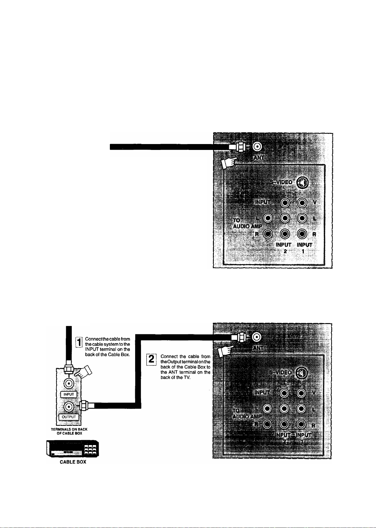
standard Antenna and External Video Connection
The following illustrations show the standard antenna and video connections which can be used for most situations.
Note: This Receiver has the “PICTURE IN PICTURE” feature. This allows you to watch two (2) live broadcasts at the
same time as long as an external video source is connected.
Standard Antenna Connection (No Cable Box or vCR)
Use this configuration when connecting the TV directly to the antenna or Cable TV system (without a Cable Box). Be
sure to select the correct mode (see the Set Up Features section in this Manual for details).
TERMINALS ON BACK OF RECEIVER
Incoming Cable
from Antenna or
Cable TV System
-4 Connect the cable from the antenna
A. (or cable system) to the ANT terminal
on the back of the TV.
Standard Antenna Connection (Cable Box)
Use this configuration when connecting the TV to the Cable TV system using a Cable Box.
Incoming Cable
from Antenna or
Cable TV System
TERMINALS ON BACK OF RECEIVER
-7-
Page 8
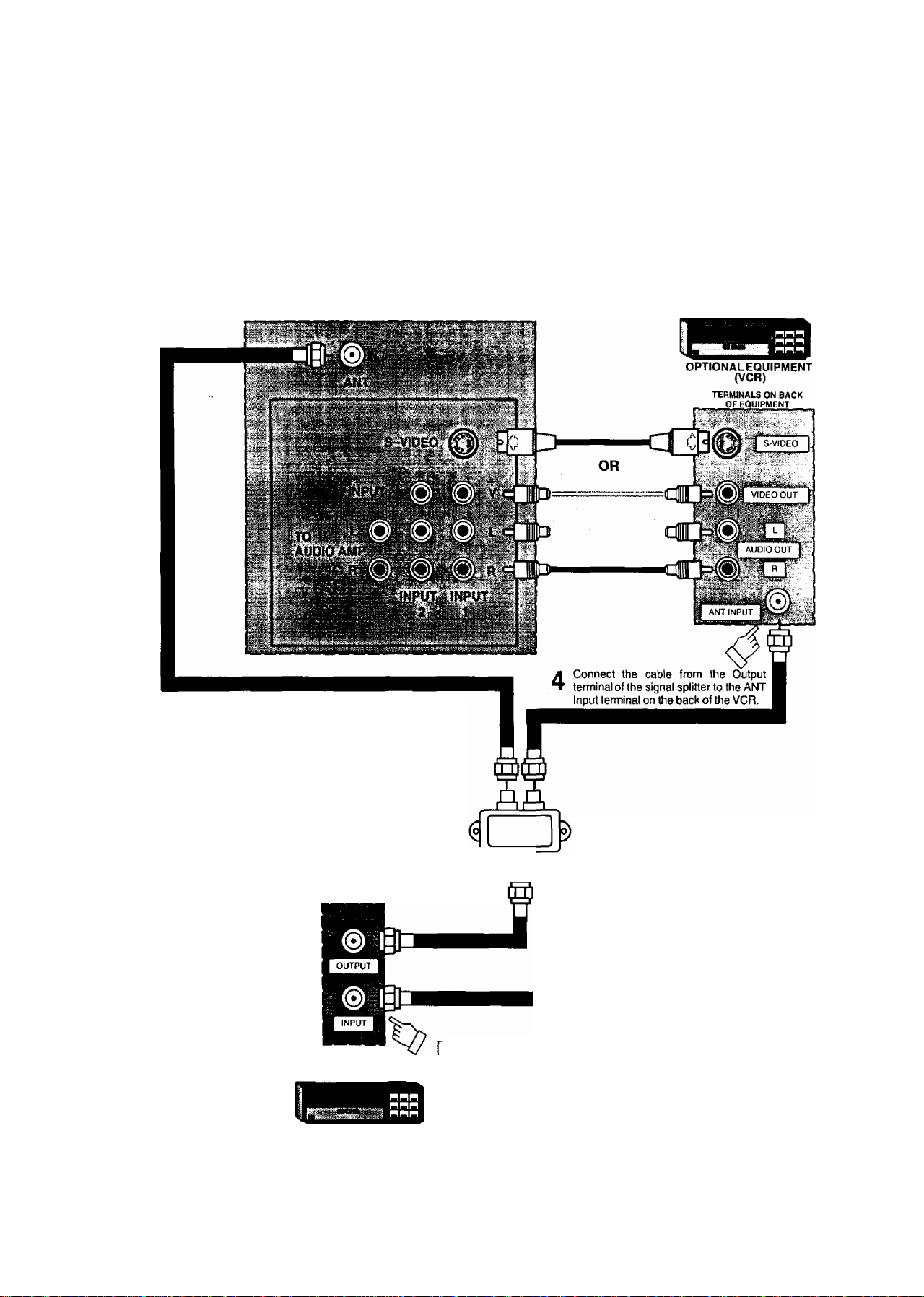
standard Antenna and External Vìdeo Connection (cont.)
Standard Antenna Connection (Cable Box and VCR)
Use this configuration when connecting the TV to the antenna or Cable TV system and a VCR (with or without a Cable
Box). Be sure to select the correct mode (see the Set Up Features section in this Manual for details). This configuration
is also recommended for the PIP Feature.
S-Video connection is optional
and overrides the standard Video
connection when connected.
TERMINALS ON BACK OF RECEIVER
c
w ; described in the/Aud/oAirfeoConnecf/on
...... section on the next page.
Connect the cable from the Output terminal
of the signal splitter to the ANT terminal on
the back of the TV.
; Connect the cable from the OUTPUT terminal
i on the back of the Cable Box to the Input
" terminal on the signal Splitter (optional).
TERMINALS ON BACK
OFCABLE BOX
1 Connectthe cable from the antenna
1
^ I or cable system to the INPUT
' terminal on the back of the Cable
Box.
Signal Splitter
(not Included)
If a Cable Box is not used,
connect the incoming cable from
the antenna or Cable TV system
directly to the signal splitter.
Incoming Cable
from Antenna or
Cable TV System
CABLE BOX
-8-
Page 9
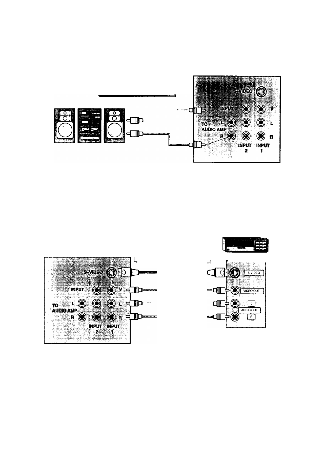
Optional Equipment Connection and Operation
To Audio AMP Connection (Stereo)
Connect to an external audio amp auxiliary input for.monitohng sound through a stereo system.
TERMINALS ON BACK OF RECEIVER
‘TO AUDIO AMP" terminals
cannot be used directly with
external speakers.
Adjustment - When an audio amp is connected to ‘TO AUDIO AMP" terminals:
1. Select INT. SPEAKERS “ON” Mode. {Refer to the Audio Menu TV Speakers section.)
Set volume of audio amp to near minimum.
Adjust volume of TV to desired listening level.
Adjust volume of audio amp to match the level of TV.
Select INT.TV SPEAKERS ‘OFF&VAO’’ (Variable Audio Output) Mode. {Refer to the Audio Menu TV Speakers
section.)
6. Audio bass, treble, balance, volume, and mute can now be controlled by the TV Remote Control.
NOTE: When Selecting INT. TV SPEAKERS “OFF&FAO" {Fix Audio Output) Mode, the TV sound output is always at a
constant level and cannot be changed from the TV {Refer to the Audio Menu TV Speakers section).
AudioA/ideo Connection
S-Video connection is optional
TERMINALS ON BACK OF RECEIVER
Operation
1. Connect optional equipment as shown to INPUT 1 or 2 terminals. If S-Video is to be used, connect S-Video (YC)
connector to S-Video terminal of INPUT 1 instead of connecting the standard video cable.
2. Select the desired Video mode by pressing the TVA/IDEO button.
3. Operate optional equipment (VCR-VDP) as instructed in Optional Equipment manual.
NOTES:
• You must select the same VIDEO Mode that the equipment is connected to.
• Connection of optional S-VIDEO jack automatically disconnects the Normal Video Input 1 jack.
and overrides the standard Video
connection when connected.
OR
I
OPTIONAL EQUIPMENT
TERMINALS ON BACK
OF EQUIPMEtfT
-9-
Page 10
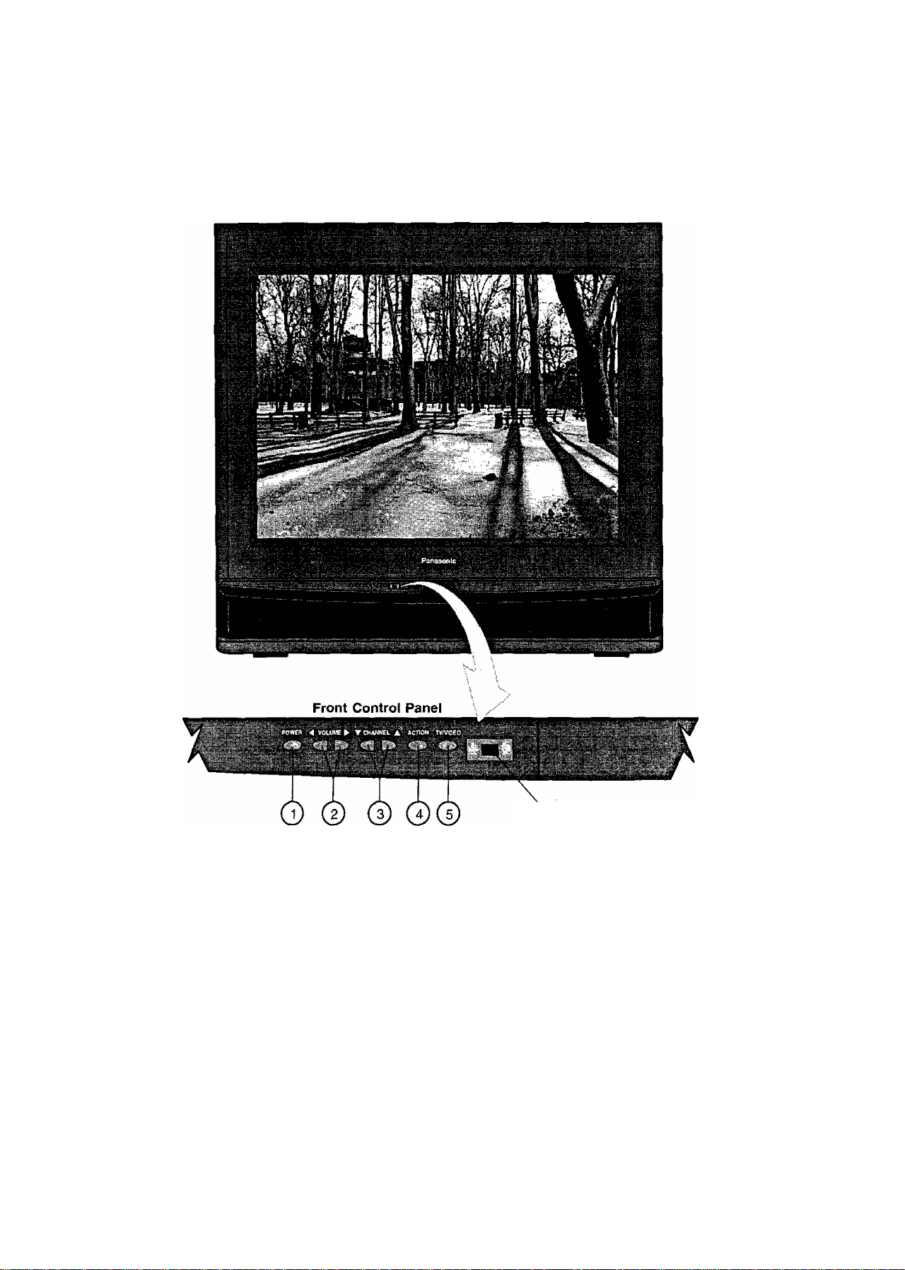
Location of Controls (Receiver)
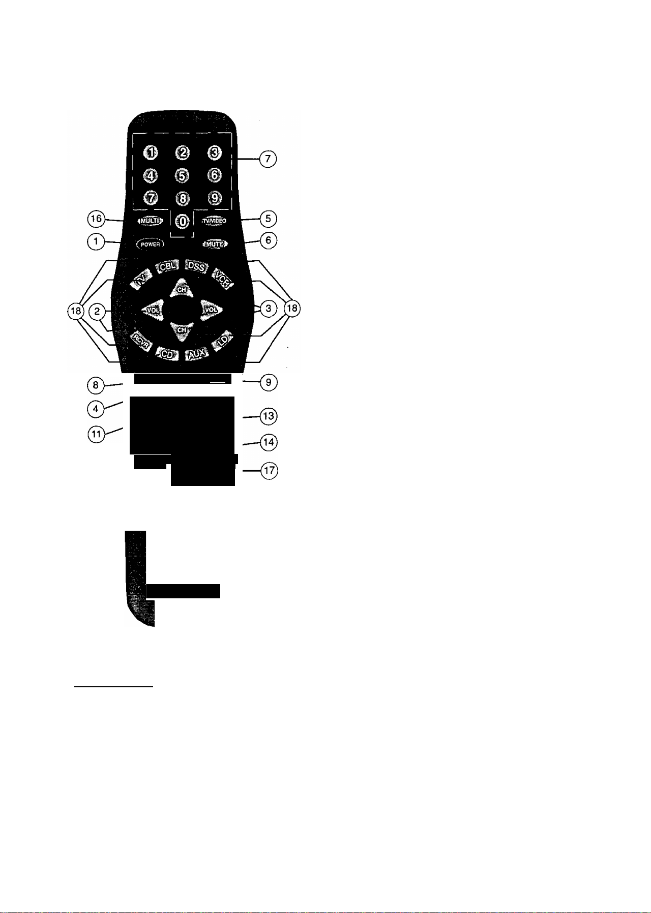
Remote Control
Sensor
Quick Reference control Ôperàtioh (Receiver)
Power Button - Press to turn ON or OFF.
Volume Buttons - Press to adjust Sound Level. Press to adjust Audio Menus, Video Menus, and select
©
operating features when menus are displayed.
Channel Buttons - Press to select programmed channels. Press to highlight desired features when menus are
displayed.
Action Button - Press to display Main Menu and access or exit On-Screen feature and Adjustment Menus.
(5) TVA^ideo Button - Press to select TV or one of two Video Inputs, for the Main Picture or the PIP frame {when
PIP frame is displayed).
-10-
Page 11
(SH
Location of Controls for the Remote Unit
Basic Remote Control Functions
The following is a basic oven/iew of the remote control unit for
television op^ation. Ensure the TV mode is selected by initially
pressing .
Power Button - Press to turn the TV ON or OFF.
©
Volume Buttons - Press to adjust TV sound level. Use
©
with Channel buttons to navigate in menus.
Channel Buttons - Press to select channels. Use with
©
Volume buttons to navigate in menus.
Action Button - Press to display Main Menu and
©
access or exit On-Screen feature and Adjustment
Menus.
TV/Video Button - Press to select TV or one of two (2)
©
Video Inputs, for the Main Picture or the PIP frame
(when the PIP frame is displayed).
Mute Button - Press to mute sound. A second press
©
returns sound.
Numeric Keypad “0 through 9” Buttons - Press
©
fACTIONl <t«CArO»
I REW PLAY FF
MOVE SIZE PIP
¡ DBI i
' REC STOP PAUSE ,
I o
TV/VCR
FREEZE
SEARCH SWAP
mm
iux t ^
VCR/DSS CH
PIP CHANNEL , [
^ ■ €a> j
1
I
desired channel number to access any channel.
R-Tune (Rapid Tune) Button - Press to switch to the
©
previous channel.
Recall Button - Press to display Time, status of Sleep
©
Timer, Channel, Video Mode, Channel Caption (Station
Identifier) and Audio Mode.
Size Button - Press to select size of PIP frame (when
the PIP frame is displayed).
Move Button - Press to position PIP frame to any comer
of the Main Picture (when PIP frame is displayed).
isl
Panasonic
Home Theater
Remote Control
Helpful Hints:
If the selected component does not respond to the
remote control, ensure that the proper mode is
selected. First, press the Mode Selection Button
that corresponds to that component. For example,
after first pressing the TV Mode Button, the remote
will remain in the TV mode for any following
commands. If a different mode button is pressed
while operating the television, the TV mode button
must be pressed again to reset the TV mode
condition.
Freeze Button - Press to stop action in the Main Picture
or PIP frame (when the PIP frame is displayed).
PIP (Picture In Picture) Button - Press to display the
®
PIP frame, press again to remove PIP frame.
^ Swap Button - Press to interchange PIP frame with
Main Picture (when the PIP frame is displayed).
Search Button - This button is used to select PIP Search
©
to automatically scan channels within the PIP Frame.
Multi Button - Programmable to operate up to six (6)
©
Remote Function buttons simultaneously.
VCR Function Buttons - Programmable to operate
many brands of VCR’s.
Mode Selection Buttons - Selects the operation mode
®
for the remote control.
VCR/DSS (PIP) Channel Buttons - These buttons are
©
used to select VCR or DSS channels Up or Down, or to
change the channels within the PIP Frame.
NOTE: For more information on the Remote Control, please
refer to the Remote Control Quick Reference
Functional Key Chart.
-11 ^
Page 12

:
...................
Remote Control
Quick Reference Functional Key Chart
KEY MODE FUNCTION
o e o
0 6 0
O 0 o
0
.......
4gg^
TV
VCR
CABLE. DSS
RECEIVER/AMPLIHER
CD PLAYER
LD PLAYER
ALLCOMPONENTS Programmable Button That Can Operate Up To Six Remote
TV Selects the TV Input Mode
ALL COMPONENTS Turns On and Off Selected Components
TV, DSS, VCR, LDP
CABLE
RECEIVE R/AMPLI FI ER
Selects Channel
Selects Channel
Selects Channel
0 Selects Tuner
0 Selects CD Player
0 Selects Tape Cassette Player
® VCR1
0 VCR 2
0 VCR3
Selects Track Number
Selects Track Number
Functions At Once
Mutes TV Audio
Mutes Audio
Mutes Audio
%
V
TV
CABLE Cable Mode Selection for Remote Control
DSS (DIGITAL SATELLITE
SYSTEM)
VCR
RECEIVER/AMPLIFIER
COMPACT DISC CD Mode Selection for Remote Control
CASSETTE PLAYER,DVD
LASER DISC PLAYER LD Mode Selection for Remote Control
TV
CABLE
DSS
LDP
CD
RECEIVER/AMPLIFIER
DVD
TV Mode Selection for Remote Control
DSS Mode Selection for Remote Control
VCR Mode Selection for Remote Control
Receiver/Amplifier Mode Selection for Remote Control
AUX Mode Selection for Remote Control
Enables User to Operate a Tape Cassette Player,
or Digital Video Disc
Channel Up/Down, Menu Navigation
Channel Up/Down
DSS Guides and Menu Navigation
Skip
FF. REW
Preset or Tuning Frequency
Skip FWD/Skip REW
TV
CABLE
DSS
RECEIVER/AMPLIFIER
VCR
LDP
Volume Up/Down, Menu Navigation
Volume Up/Down
DSS Guides and Menu Navigation
Volume Up/Down
TV Volume Up/Down
TV Volume Up/Down
-12-
Page 13

Remote Control
Quick Reference Functional Key Chart
^*d3i
Pirn
’■■i« ■ ■ ■ ............................■;
FF
ess
BC^
- REC
; V.. ^
•i ' .-1 •
■ '■ ■■ ;
(jB]:
...............'1
STOP
. ■ 4*' ..
MODE
LDP
TV
CABLE
VCR
DSS
RECEIVER/AMPLIFIER
CD
TAPE CASSETTE PLAYER
TV
DSS
TV
DSS
VCR
LDP
TV
DSS
VCR
LDP
TAPE Rewind
CD
DVD Rewind
TV
DSS Enter/Select
VCR Play
LDP Play
TAPE Play {in Normal Direction)
CD Play
DVD Play
TV
DSS ExiVCIear
VCR Fast Forward
LDP
TAPE Fast Forward
CD
DVD
DSS One Touch Record in DSS Mode
VCR
TAPE
CABLE VCR Record
TV
DVD Stop
VCR Stop
LDP Stop
TAPE
CD
CABLE
DVD
TV
VCR
LDP
TAPE Pause
CD
CABLE VCR Pause
TV
VCR
DSS
CABLE
TV PIP Channel Up/Down {2 Tuner PIP Models Only)
VCR
DSS
CABLE VCR Up/Down
SideA/B
Selects Previously Tuned Channel
Selects Previously Tuned Channel
Selects Previously Tuned Channel
Selects Previously Tuned Channel
Switches between AM and FM
Selects Next Disc
Selects Tape Cassette Player A or B
Activates TV Menus
Acts as Menu Button for DSS
Displays Channel, Time, and Audio Mode
Displays Current DSS Settings
Displays Current VCR Settings
Displays Current LOP Settings
PIP Move
DSS Guide
Rewind
Rewind
Selects Previous Track
PIP Size
PIPOn/Off
Fast Forward
Selects Next Track
Fast Forward
Record
Record
PIP Search
Stop
Stop
VCR Stop
Pause
PIP Swap
Pause
Pause
Pause
PIP Freeze
Selects TV/VCR Mode
Selects TV/DSS Mode
Selects TVA/CR Mode
Channel Up/Down
Channel Up/Down
FUNCTION
-13-
Page 14

Control Operation
Helpful Hintsi
Press the TV Mode Selection button to operate TV
Remote functions, if necessary.
Power Button - Press the POWER button after
selecting a mode to turn ON. Press again to turn OFF.
Volume Button - Press the VOLUME (VOL)
LEFT or RIGHT button for desired listening level (when
On-Screen menus are not displayed).
Located On Remote Control
Increases
A
Volume Level
Channel Buttons (UP/down)
Press the CHANNEL (CH) UP/DOWN button to sequen
tially scan through programmed channels (when OnScreen menus are not displayed).
NOTE: Press the TV Mode button to operate TV
Remote functions, if necessary.
Located On Remote Control
Selects Next
HigherChannel
Selects Next
Lower Channel
Numeric Keypad (O through 9 Buttons)
These buttons let you directly access any channel.
(Example: press 5 for channel 5; press 1, then 3 for
channel 13). For channels over 99, press three number
buttons.
Mute Button — Press the MUTE button to quickly
reduce sound level. “MUTE” will appear on screen
momentarily. Press again to restore sound.
Helpful Hints:
Helpful information will display On Screen momen
tarily when Receiver is first turned on and when the
channel is changed.
Note: if “SPEAKER OFF” is displayed On Screen
after pressing the VOLUME button, refer to
Audio Menu to turn Speakers “ON”.
^ (D
(¿1
VCR Function Buttons - Th© VCR function
buttons have been designed to operate numerous brands
of VCRs. The infrared code must be programmed prior to
use. (Please refer to Programming the Universal
Remote for programming instructions.)
Note: Press the VCR Mode Selection button to operate
VCR Remote functions.
r
MOVE
Dcr STOP PAUSE
TV/VCR VCR/DSS CH
FREEZE PIP CHANNEL
O <S> CD
'
-----------------------------
REW
PLAY
SIZE
Search SMAP
FF
PIP
r^s>
E
1
-14-
Page 15

TV/VideO Button - Press the TV/VIDEO button
to select desired input for Main Picture or PIP frame
(when the PIP is displayed).
Signal coming from;
REARVIDEO/AUDIOINPUT2TERMINALS
REAR VIDEO/ALIDIOINPUH
TERMINALS
TV or CABLE
Signal coming from:
REAR VIDEO/AUDIO INPUT 2 TERMINAL^
REAR VIDEO/AUDIO INPUTS
TERMINALS
TV or CABLE
PIP Frame
RGCSII Button — Press the RECALL button to
review:
Q] Audio Mode status
E] CH number or Video Input selected
0] Sleep Timer status
g] Clock time
[5] Channel Caption (Station Identifier)
m
Multi Button
The MULTI button can be programmed to operate
up to six (6) Remote function buttons at the same
time.
For Example: TV Power/On, VCR Power/On and
Cable box Power/On (selected brands) can be operated
at the same time with one press of the MULTI button.
Procedure
1. First program the Remote for the selected device
Infrared access code. Confirm that the Remote
Control is compatible with the equipment.
2. Face the Remote Control transmitter away from all
equipment remote sensors.
3. Press and hold the Remote POWER button, then
press and hold the ACTION button down at the
same time for three seconds. (All previous
commands are erased.)
PRESS AT THE SAME TIME
FOR THREE SECONDS
4. After three seconds, let go of the POWER and
ACTION buttons.
5. Press the MULTI button.(Waiting more than 30
seconds without pressing another button will exit the
programming mode.)
6. Press a maximum of six (6) function buttons on the
Remote.
Each button you press is equal to one function. If six
(6) Remote button functions are entered, all will
register in the MULTI button memory in the
sequence entered. When finished, press the MULTI
button to end the program mode.
The following is an example flow chart of Remote
functions that can be programmed into the MULTI
button (The VCR Mode button should be
programmed before starting procedure see pg. 30).
a
R-Tune Button - Pressing the R-TUNE (RAPID
TUNE) button will switch between the last two channels
selected on the nurneric keypad. _ _
NOTE: When rapidly scanning channels with the
CHANNEL UP/DOWN button, pressing the
R-TUNE button will switch between the last
channel scanned, and initial channel at the start
of scanning.
CHANNEL NOW
BEING VIEWED
Press Button
Press Button Again
4
CHANNEL
PREVIOUSLY \REWEO
-15-
PRESS ATTHE SAMETIME
FOR THREE SECONDS
PRESS PRESS
PRESS PRESS
PRESS TO END
PROGRAM MODE
Now you can turn the TV and VCR ON/OFF at the
same time with one press of the MULTI button.
To delete entered functions - Press and hold the
Remote POWER button then press and hold the
ACTION button down at the same time for three
seconds. Now you can enter from one to six different
Remote functions.
NOTE:
You can also program the MULTI button to perform
most individual Remote Control button functions.
Buttons which continuously perform a function as
long as press^ (Volume Up/Down, Channel
Up/Down, etc.) cannot be programmed. Only those
buttons which perform a function when initially
pressed (Power On/Off, Mute, Direct Channel
Entry, etc.) can be programmed.
Page 16

HêlptÛlHIh^^
Press the TV Mode Selection button to operate TV
Remote functions, if necessary.
PIP (Picture in Picture) Button - This
feature allows the viewer to monitor one channel
program while watching another. The monitored source
(PIP) can be a different channel or a different vidéo
source (such as a VCR) when connected to the input
jacks.
• S-Video connection will also operate the PIP feature.
• When the Main Picture is in Video mode with no
signal, the PIP will not operate properly.
PIP Operation
1. Press the TV Mode Selection button to operate TV
Remote functions, if necessary.
SwSp Button — Press the SWAP button (when the
PIP frame is displayed) to interchange what is being
viewed on the Main Picture with that of the PIP frame.
NOTE; Audio will be that of the Main Picture.
VIDEO 1
PIP CH 2
Size Button — Press the SIZE button (when the
PIP frame is displayed) to choose either the large or
small PIP frame.
SIZE
Press the PIP button (television must be ON). The
2.
PIP frame will appear at the position it was last
displayed. The Main Picture Video Source and PIP
Video Source will display on screen momentarily.
Audio will be that of Main Picture.
ptp
Main Picture
Channel
Picture in
Picture
Channel
Picture in
Picture
Frame
3. Press the PIP button again to cancel PICTURE IN
PICTURE feature (if desired).
PIP
Large PIP Frame
Small PIP Frame
Note: For PIP Video source connection, refer to the i
Standard Antenna and External Video)
Connections section. )
-1 6-
Page 17

Helpful Hints:
Press the TV Mode Selection button to operate TV
Remote functions, if necessary. ^
Search Button - The search button allows
you to scan channels in “Channel Scan memory” one at
a time. This feature will work with or without an external
video signal as the Main Picture.
Freeze Button - Press the FREEZE button to
stop action in the PIP frame.
FREEZE
Main
Picture
Freeze
Frame
Note:
Pressing the FREEZE button when the PIP frame is
not displayed will stop action in the Main Picture and
display it within a PIP frame.
Pressing the FREEZE button When PIP frame iS;
displayed will stop action in the PIP frame. Press the
FREEZE button again to continue action.
Press the PIP button to delete PIP frame.
SEARCH
Press Search
to Scan
Search Operation
1. Press the SEARCH button. A PIP frame will appear
on the Main Picture. The PIP frame will continuously
scan channels in sequence as programmed into
channel memory.
2.
Press the PIP button to stop Search feature on
desired picture for PIP frame. Press the SWAP
button to switch between the Main Picture and the
PIP frame. Press the PIP button again, the PIP
frame will disappear.
Move Button — This feature allows the viewer to
move the PIP frame to any corner of the Main Picture.
Activate the PIP frame. Press the MOVE button to move
the PIP frame to the desired location.
MOVE
PIP Channel Buttons
Press the PIP CHANNEL UP/DOWN button while the PIP
frame is displayed to sequentially scan through Channels.
PIP CHANNEL
Scan Channel Down
(next lower)
Scan Channel Up
(next higher)
-17-
Note: Each time MOVE button is pressed (when the
PIP frame is displayed), the PIP frame will move
counterclockwise as illustrated.
Page 18

Main Menu (icons)
Located On Remote Control
Menu is Displayed
Displays and Exits Menus
1. Press the ACTION button to display the Main Menu with Icons.
2. Press the CH UP/DOWN and the VOL LEFT/RIGHT buttons to select the desired Icon when the Main Menu is
displayed (selected Icon will be indicated in Red).
3. Press the VOL buttons for left and right movement and the CH buttons for up or down movement.
4. To exit the Main Menu first select the EXIT Icon, then press the ACTION button.
Bilingual Menu Selection
The Language Menu is factory set to ENGLISH. Follow
these instructions to change the Language Menu to
French and back to English.
1. Press the ACTION button to display the Main Menu.
2. Press the CH DOWN and VOL RIGHT buttons to
select the SET-UP Icon.
3. Press the ACTION button to display the SET-UP
Menu.
4. Press the CH UP or DOWN button to highlight
“ENGLISH FRANÇAIS”.
5. Press the VOL LEFT or RIGHT button to highlight
ENGLISH or FRANÇAIS.
6. Press ACTION button twice to exit menus.
-18-
Page 19

Picture Adjustments
Picture Norm
Color
Tint
Brightness
Picture
Sharpness
Located On Remote Control
Picture Nornri — This feature is used to reset Color,
Tint, Brightness, Picture and Sharpness adjustments back
to a factory preset level.
1. Press the ACTION button to display the Main Menu.
2. Press the CH UP/DOWN and VOL LEFT/RIGHT
buttons to select the Picture Icon.
3. Press the ACTION button to display the Picture
Adjustment Menu.
yPICTURE;
Selects or Adjusts
Features when
Menu is Displayed
Displays and Exits Menus
Selects Desired
Feature when
Menu is Displayed
PICTURE NORM
COLOR J
TINT ;
BRIGHTNESS
E
^SHARPNESS
4. Press the CH UP or DOWN button to highlight
PICTURE NORM (if necessary).
5. Press the VOL LEFT or RIGHT button to select
“SET’ to Normalize Color, Tint, Brightness, Picture
and Sharpness.
6. Press ACTION button twice to exit menus.
i^PfCTURE
.r m
:tminihiM- -
iHiiimnii: - -
niimHimMitiMMiMil
nimtMiin - - - -
Color, Tint, Brightness, Picture and Sharpness Adjustments
1.
Press the ACTION button to display the Main Menu.
Press the CH UP/DOWN and VOL LEFT/RIGHT
2.
buttons to select the Picture Icon.
3.
Press the ACTION button to display the Picture
Adjustment Menu.
Helpful Hints:
Picture Adjustments:
• COLOR - adjust for desired color intensity.
• TINT - adjust for natural flesh tones.
• BRIGHTNESS - adjust so dark areas of picture
just become black for a crisp detail.
• PICTURE - adjust the white areas of the picture for
desired viewing levels.
• SHARPNESS - adjust for best clarity of outline
detail.
4.
5.
6.
7.
-19-
*^;.PICTURE NORM . NO . ..
0- COLOR 31 immiiiMi
^qTINT „ ■ ------ I - - .
BRIGHTNESS' : IMM) M tMH-
^PICTURE iMMiiimnmiit’iniMT
SHARPNESS - -
Press the CH UP or DOWN button to highlight the
desired Picture Adjustment (Color, Tint, Brightness,
Picture or Sharpness).
Press the VOL LEFT or RIGHT button to adjust your
selection. (The selected Picture Adjustment will be
displayed).
Repeat steps 4 and 5 for the remaining Picture
Adjustments.
Press ACTION button twice to exit menus.
.....................
Page 20

Audio Adjustment
Audio Norm
Bass
Treble
Balance
(Audio) Mode
Al Sound
Surround
TV Speakers
Audio Norrn — This feature is used to reset BASS,
TREBLE and BALANCE back to a factory preset level.
1. Press the ACTION button to display the Main Menu.
2. Press the CH UP/DOWN and VOL LEFT/RIGHT
buttons to select the Audio Icon.
3. Press the ACTION button to display the Audio
Adjustment Menu.
Located On Remote Control
Selects or Adjusts
Featu res when 11 action J
Menu is Displayed
Displays and Exits Menus
Selects Desired
Feature when
Menu is Displayed
m AUDIO NORM NO ^ .
r^ BASS SHMUiiUtUtltl
g": TREBLE tlllMMIliiMM
r:S..BALANCE ■■■■■■■:::----------- +
-MODE ■ ■ ■ , SAP MONO
Al SOUND OFF SURROUND
j|n^PE AKERS ON
--------------
-------------
’5
;
e
4.
Press the CH UP/DOWN button to highlight AUDIO
NORM.
5.
Press the VOL LEFT/RIGHT button to select “SET’
to Normalize Bass, Treble, and Balance.
6.
Press ACTION button twice to exit menus.
Bass, Treble, and Balance
Adjustment
1. Press the ACTION button to display the Main Menu.
2. Press the CH UP/DOWN and VOL LEFT/RIGHT
buttons to select the Audio Icon.
3. Press the ACTION button to display the Audio
Adjustment Menu.
Helpful Hints:
• BASS - To increase or decrease the Bass
response.
• TREBLE - To increase or decrease the Treble
response.
• BALANCE - To emphasize the Right and Left
Speaker’s volume.
_________________________
AUDIO .NORM NO ,
BASS 31 lllllMlIllillll
TREBLE mMMtnmni----
Rm ancR
MODE IBre3 sap mono
Ai SOUND OFF SURROUND ON
TV SPEAKERS ON * : ^
4. Press the CH UP/DOWN button to highlight BASS,
TREBLE, or BALANCE.
5. Press the VOL LEFT/RIGHT button to adjust for de
sired audio response.
6. Repeat steps 4 and 5 for remaining Audio functions.
7. Press ACTION button twice to exit menus.
|NOTE: When TV SPEAKERS are in the OFF&FAO
mode, the BASS, TREBLE, and BALANCE
adjustments will indicate “31 FAO”.
-------
-------------------
--------.4- —
-20-
Page 21

Audio Adjustment (cont.)
Located On Remote Control
Selects or Adjusts
Features when 11*ction|
Menu is Displayed
Displays and Exits Menus
(Audio) Mode Stereo/SAP/Mono
When Audio is broadcast in Stereo or SAP, an ON
Screen display will appear on initial “Turn On” and
"Channel Change”. The available choices will be
indicated in red.
1. Press the ACTION button to display the Main Menu.
2. Press the CH UP/DOWN and VOL LEFT/RIGHT
buttons to select the Audio Icon.
3. Press the ACTION button to display the Audio
Adjustment Menu.
Al Sound — This feature regulates the volume
between programs and commercial audio to maintain a
constant sound output level.
1.
Press the ACTION button to display the Main Menu.
2.
Press the CH UP/DOWN and VOL LEFT/RIGHT
buttons to select the Audio Icon.
3.
Press the ACTION button to display the Audio
Adjustment Menu.
Pi.. .
AUDIO NORM NO
BASS 31 ilMIlllinilill —
TREBLE MlllllimKIU —--—
■ BALANCE' ■ ■ ■
MODE iigrWEdi SAP MONO
Al SOUND OFF f!:: SURROUNOT^^ON
TV SPEAKERS ON - --
4. Press the CH UP/DOWN button to highlight Al
SOUND.
5. Press the VOL LEFT/RIGHT button to select Al
SOUND ON or OFF.
6. Press ACTION button twice to exit menus.
e-Si
iAUDIQ
^ I 1
^ -.M
....
^dio'norm'no'-
8ASS4 ;: V 31 iMMlMninnt -—-—
ITREBLE
miimiiinm
^balance
MODE
SAP MONO
4. Press the CH UP/DOWN button to select MODE.
5. Press the VOL LEFT/RIGHT button to select Stereo,
SAP {Second Audio Programming) or Mono.
6. Press ACTION button twice to exit menus.
Helpful Hints:
STEREO - Two channel Audio reception.
SAP - Second Audio Programming (typically used
for bilingual audio).
MONO - Use when stereo signal is weak.
Surround — Use the Surround Feature to enhance
audio response when listening to Stereo broadcasts.
1. Press the ACTION button to display the Main Menu.
2. Press the CH UP/DOWN and VOL LEFT/RIGHT
buttons to select the Audio Icon.
3. Press the ACTION button to display the Audio
Adjustment Menu.
te»:,:;.
.......
...3!
M AUDIO NORM NO , f,.
BASS 3immnumiu -——- ii-ti
^ TREBLE MUIIMIMNU)
— BALANCE
Ш IVIODE ISIERECi SAP MONO ^
Щ Al SOUND OFF - SURROUND ON J
H TV SPEAKERS ON
--------
---------
4. Press the CH UP/DOWN button to highlight
SURROUND.
5. Press the VOL LEFT/RIGHT button to select
SURROUND ON or OFF.
6. Press ACTION button twice to exit menus.
--------—: if >
-21 -
Page 22

Audio Adjustment (cont.)
Located On Remote Control
Selects or Adjusts
Features when
Menu is Displayed
Displays and Exits Menus
Selects Desired
Feature when
Menu is Displayed
TV Speakers — This feature is used to turn the
internal speakers “ON" or “OFF", it is used when the
Receiver is connected to an External Audio Amplifier.
{Refer to “To Audio Amp” section for further informa
tion.)
1. Press the ACTION button to display the Main Menu.
2. Press the CH UP/DOWN and VOL LEFT/RIGHT
buttons to select the Audio Icon.
3. Press the ACTION button to display the Audio
Adjustment Menu.
AUDIO NORM NO
iBASS v' V; 31 UltllllMllMl)
STREBLE^-^ ifimJIlUIMM
; BALANCE —---"d
:M0DE . SAP. MONO
lAI SOUND OFF SURROUND ON
TV SPEAKERS ON
4.
Press the CH UP/DOWN button to highlight TV
SPEAKERS.
5.
Press the VOL LEFT/RIGHT button to select TV
Speakers ON, OFF&VAO or OFF&FAO.
• ON - TV SPEAKERS operate normally.
• OFF&VAO (Variable Audio Output) - TV
SPEAKERS off, the sound output varies according
to the TV volume, use the TV remote to control
the volume, muting, bass, treble, and balance of
the External Audio System.
• OFF&FAO (Fixed Audio Output)-TV SPEAKERS
off, sound output remains constant and cannot be
controlled from the TV. Use the External Audio
System to control sound levels.
Press ACTION button twice to exit menus.
6.
-22-
Page 23

Lock
Lock Game Guard
Prevents video games and other video sources from
being viewed. Channel 3, 4, and alt video inputs are
locked out for 12, 24, or 48 hours.
NOTE: Be sure to understand this feature before^
attempting its use. Use a code that you will;
easily rememt^r
1. Press the ACTION button to display the Main Menu.
2. Press the CH UP/DOWN and VOL LEFT/RIGHT
buttons to select the Lock Icon.
3. Press the ACTION button to display the Lock
(Game Guard) Menu.
J'J L ^
^ LOCK CH 3,4, AND VIDEO INPUTS
HOW LONG?
Mr'ENTER CODE ■
ifeSET .:
12 HOURS
Unlock Game Guard
To unlock the Game Guard feature, repeat steps 1
through 3 from Lock Game Guard. Enter the same
3-digit code previously used in step 5 with Remote
Control Keypad.
^ f. . ..... :f,.. .y...„.^..._ .. . . ...: ...
GAME GUARD
LOCKED '
LOCK ACTIVATED
ENTER CODE TO CH'ANGE SETlINGi^ J
Enter Same 3-Digit Code Previously Used
4. Press the VOL RIGHT button to select the desired
hours (12, 24, or 48) for Game Guard (Lockout) to
be activated.
5. Press the CH DOWN button to select “ENTER
CODE". Then enter a 3-digit code with the Remote
Control Keypad.
IMPORTANT NOTE: Use a code you can easily
remember.
6. Press the VOL LEFT/RIGHT button after entering
3-digit code. "Game Guard Locked” will display On
Screen.
Game Guard Activated
If 3-Digit Code is the Same
If 3-Digit Code is not the Same
-23-
Page 24

Channel Caption
Located On Remote Control
Selects or Adjusts
Features when
Menu is Displayed
Displays and Exits Menus
4.
Press the VOL LEFT/RIGHT button, or use the
Remote Control Keypad, to enter channel number
you wish to assign a Station Identifier.
5.
Press the CH DOWN button to select “ENTER
CAPTION”.
Channel Caption (Station Identifier)
This feature allows you to enter the call names of up to
30 stations into memory (using up to four (4) characters
for each station). The call name will then display along
with the channel number when changing channels or
pressing RECALL.
.Channel Caption
{Station Identifier)
1. Press the ACTION button to display the Main Menu.
2. Press the CH UP/DOWN and VOL LEFT/RIGHT
buttons to select the Channel Caption Icon.
3. Press the ACTION button to display the Channel
Caption Menu.
111
ENTER CHANNEL NUMBER
ENTER CAPTION
A TO MOVE
I T CURSOR
6. Press the VOL LEFT/RIGHT button to select first
character in Station Identifier. Then press the CH
DOWN button to move cursor to the second position
and repeat until the complete Station Identifier is
entered (up to four (4) characters).
7.
Press the CH UP/DOWN button to select "ENTER
CHANNEL NUMBER”. Then repeat steps 4 through
6 to continue adding Channel Station Identifier(s).
8.
_ Press ACTION button twice to exit menus.
NÖTE: to delete a Channel identifier)
t from: menrfory alt four character positions must
_ display dash mark {-).
4 ► TO SELECT
CHARACTER
When the Maximum amount of station identifiers are
entered, “FULL” will be displayed in the characters
position.
-24-
Page 25

Timer Features
» Sleep Timer
• Program Timer
Special Feature:
Automatic “OFF” after 90 minutes.
The TV has a special feature that will shut itself OFF
after 90 minutes when turned ON by the program
timer unless a function key is pressed during the 90
minutes.
This feature is useful so that the TV will not remain
ON unattended for an extended period of time.
Programming the OFF timer will also cancel the
automatic OFF feature.
Sleep Timer —This feature is used for automatic
turn off in 30, 60, or 90 minutes.
NOTE: Display will flash 3,2, and 1 to indicate the last
three remaining minutes prior to turn off. The
Recall display will also appear.
1. Press the ACTION button to display the Main
Menu.
2. Press the CH UP/DOWN and VOL LEFT/RIGHT
buttons to select the Timer Icon.
3. Press the ACTION button to display the Timer
Control Menu.
SLEEP TIMER NO
R^GRiAM:.TiMER"-^ : T'”'"■
(
■'■■J...','" QpfT __ '..“I
i: SET,:NO.;
^ Jf V iiilirfc
4. Press the VOL RIGHT button to select NO, 30,60
or 90 minutes (Sleep Timer will be activated).
5. Press ACTION button twice to exit menus.
NOTE: To deactivate Sleep Timer repeat steps 1
Helpful Hints:
Press the RECALL button to display the remaining
minutes for Sleep Timer, the time will display in the
bottom left comer.
CHANNEL 3 '
-----
%
through 4. in step 4 select “NO” instead of
minutes.
Program Timer — This feature is capable of
turning the TV on, tuned to a desired channel and off at a
predetermined time (one day or everyday).
NOTE: The clock must be set for this feature to operate.
(Refer to the Set-Up Menu to set time.)
Press the ACTION button to display the Main Menu.Press the CH UP/DOWN and VOL LEFT/RIGHT
buttons to select the Timer Icon.
Press the ACTION button to display the Timer
Control Menu.
4. Press the CH DOWN button to select “ON" (time).
5. Press the VOL LEFT/RIGHT button repeatedly to
set hours (set AM/PM accordingly).
6. Press the CH DOWN button to select the minutes
position.
7. Press the VOL LEFT/RIGHT button repeatedly to
set minutes.
8. Press the CH DOWN button to select “OFF” (time).
9. Repeat steps 5 through 7 for setting “OFF” (time).
10. Press the CH DOWN button to select “CHANNEL”.
11. Press the VOL LEFT/RIGHT button or use the
RerTKite Control Keypad to enter the channel number
desired when the set turns “ON”.
12. Press the CH DOWN button to select “SET’.
13. Press the VOL RIGHT button to select:
• NO - not activated.
• ONE DAY - activated.
• DAILY - activated.
NOTE: To deactivate Program Timer select “NO" in step
13.
14. Press ACTION button twice to exit menus.
..........
Helpful Hints:
• If you see “GAME GUARD” in the upper right hand
corner, the channel or Video Input you have selected
has been locked out.
• If the Program Timer “ON” functions while the set is
operating, the set will automatically tune to the chan
nel designated in the Timer Program.
-25-
Page 26

Set-Up Features
• Set Time
• Antenna (TV or Cable)
• Auto Program
• Manual Program
• CC (Closed Caption) on Mute
• CC (Closed Caption) Mode
• English or Français (French)
Located On Remote Control
Selects or Adjusts
Features when
Menu is Displayed
Displays and Exits Menus
Selects Desired
Feature when
Menu is Displayed
ANT (TV or Cable Tuning Mode) - The proper
Input mode must be selected for the type of signal at the
antenna input.
• TV mode is used when the Receiver is not
connected to a cable TV system, for example when
using a VHF/UHF antenna (channels 02 - 69).
• Cable mode is used when the Receiver is con
nected to a Cable TV system and you are not using
a cable company converter box (channels 01 -
125).
Press the ACTION button to display the Main Menu.
Press the CH UP/DOWN and VOL LEFT/RIGHT
buttons to select the Set-Up Icon.
Press the ACTION button to display the Set-Up
Menu.
ANT
fAÜTO PROG^
I^ANUALPROG
Ç^ÏONMUTE ;
Set Time “ Clock (when set) will display on screen
at initial ‘Turn On”, after a channel change and when
pressing the RECALL button. The time must be set first
in order to operate the Program ON/OFF Timer.
1. Press the ACTION button to display the Main Menu.
2. Press the CH UP/DOWN and VOL LEFT/RIGHT
buttons to select the Set-Up Icon.
3. Press the ACTION button to display the Set-Up
Menu, Set Time will be highlighted.
4. Press the VOL LEFT/RIGHT button to set hours
(set AM/PM accordingly).
5. Press the CH DOWN button to select minutes
position.
6. Press the VOL LEFT/RIGHT button repeatedly to
set minutes.
7. Press ACTION button twice to exit menus.
4. Press the CH DOWN button to highlight ANTENNA.
5. Press the VOL LEFT/RIGHT button to select TV or
CABLE.
6. Press ACTION button twice to exit menus.
-26-
Page 27

Set-Up Features (cont.)
Located On Remote Control
Selects or Adjusts
Features when
Menu is Displayed
Displays and Exits Menus
Selects Desired
Feature when ‘
Menu is Displayed
Manual Program
This feature allows you to select which channels are
placed into Channel Scan Memory.
1. Press the ACTION button to display thè Main Menu.
2. Press the CH UP/DOWN and VOL LEFT/RIGHT
buttons to highlight the Set-Up Icon.
3. Press the ACTION button to display the Set-Up
Menu.
Auto Program
This feature allows you to place all channels with a video
signal into Channel Scan Memory.
1. Press the ACTION button to display the Main Menu.
2. Press the CH UP/DOWN and VOL LEFT/RiGHT
buttons to select the Set-Up Icon.
3. Press the ACTION button to display the Set-Up
Menu.
4.
Press the CH DOWN button to highlight “AUTO
PROG”.
5.
Press the VOL LEFT/RIGHT button to start Auto
Programming. Channels will automatically advance
until all channels have been scanned.
6.
Press ACTION button twice after completion of
Auto Programming to exit the Set-Up Menu.
NOTE: Channel numbers with signal present will turn
blue which indicates stored in Channel Scan
Memory.
4. Press the CH DOWN button to highlight “MANUAL
PROG”.
5. Press the VOL LEFT/RIGHT button to display the
Manual Programming Menu.
6.
Use the CH UP/DOWN button or the Remote
Keypad “0 through 9 buttons” to select channels.
7.
Press the VOL RIGHT button to add channel(s) to
memory (Blue). Press the VOL LEFT button to
delete channels from memory (Yellow).
8.
Repeat steps 6 and 7 to continue adding or deleting
channels.
9.
Press ACTION button twice to exit menus.
-27-
Page 28

Set-Up Features (cont.)
iCClOn Mute
Activates the On-Screen Closed Captioning when the
MUTE button on the Remote Control is pressed. To
deactivate press the MUTE button again.
NOTE: This feature only functions when the Closed
Caption Mode is in the “OFP position. The
program being viewed must be broadcast with
Closed Caption. (Refer to your local TV guide.)
1.
Press the ACTION button to display the Main Menu.
2.
Press the CH DOWN and VOL RIGHT buttons to
select the Set-Up Icon.
Press the ACTION button to display the Set-Up
3.
Menu.
SETSriME
ANTi
AUTOl^ROG]
^MANUAlSliROG
ON MUTE
4. Press the CH DOWN button to highlight “CC ON
MUTE”.
5. Press the VOL RIGHT button to select OFF, C1, or
C2 Mode.
Recommended Set-Up:
• Place CC ON MUTE into the Cl Mode.
• Press the CH DOWN button to select “CC
MODE”.
• Press the VOL RIGHT button to select “OFF”.
6. Press ACTION button twice to exit menus.
7. Press the MUTE button when the program being
viewed is broadcast with Closed Caption to activate.
Press again to deactivate.
feel Mode — This Receiver has a built-in decoder
that provides a visual depiction of the audio portion of a
television program in the form of written words across
the screen (white or colored letters on a black
background). It allows the viewer to read the dialogue of
a television program or other information.
1.
Press the ACTION button to display the Main Menu.
2.
Press the CH UP/DOWN and VOL LEFT/RIGHT
buttons to select the Set-Up Icon.
3.
Press the ACTION button to display the Set-Up
Menu.
4.
Press the CH DOWN button to select “CC MODE".
5.
Press the VOL RIGHT button to select OFF, Cl, or
C2 .
• OFF - Select to turn Closed Caption off.
• C1 - For video related information that can be
displayed (up to four (4) lines of script strategically
placed on the television screen so that it does not
obstruct relevant parts of the picture). Script
can be in any language.
• C2 - Another mode used for video related in
formation that can be displayed (up to four (4)
lines of script strategically placed on the television
screen so that it does not obstruct relevant parts
of the picture).
6.
Press ACTION button twice to exit menus.
Helpful Hints:
Closed Caption information may be transmitted on
either or both Caption Modes.
-28-
Page 29

Set-Up Features (cont.)
Located On Remote Control
Selects or Adjusts
Features when
Menu is Displayed
Displays and Exits Menus
Selects Desired
Feature when
Menu is Displayed
Bilingual Language Feature
The Language Menu is factory set to ENGLISH. Follow
these instructions to change the Language Menu to
French and back to English.
1. Press the ACTION button to display the Main Menu.
2. Press the CH DOWN and VOL RIGHT buttons to
select the SET-UP Icon.
3. Press the ACTION button to display the SET-UP
Menu.
4. Press the CH UP/DOWN button to highlight
“ENGLISH FRANÇAIS”.
5. Press the VOL LEFT/RIGHT button to highlight
ENGLISH or FRANÇAIS.
6. Press ACTION button twice to exit menus.
Helpful Hints:
Language Menu does not affect Closed Caption or other
transmitted text information.
-29-
Page 30

Programming the Remote Control Using Access Codes
The remote control can be preset for other manufacturers, by utilizing the MODE SELECTION BUTTONS for
CABLE, DSS, VCR, RCVR (a Receiver or Amplifier), CD, LD, and AUX (for Cassette Players or a DVD.)
Procedure - Code Known
Procedure for setting up the remote using the
numerical buttons.
Code From Index Sheet
□ Determine brand of device.
□ Identify code(s) associated with the brand in the
infrared code index (located in this manual on
pages 31 thru 34). Record all possible codes.
□ Confirm the device is plugged in and operating
properly.
—
_____
Press and hold the button, then the
button sojhat bpth^are pressed at the same
time forjat least 5 seconds.-
Press the desired Mode button.
Enter the 3-digit code, by using the Remote
Control Keyboard “0 through 9 buttons”.
Now yourremote is set for this code.
f?1 Press to test your device.
NOTE: Some brands have multiple codes. Repeat
the procedure using each listed code until
the device responds correctly.
If you enter an unlisted code, or if you do not
□
complete your entry within 30 seconds, the settings
will not change.
Infrared Remote Codes for Specific Components
1 Helpful Hint: Write down the code numbers for your components in the space provided below. This
1 will serve as a handy reference whenever you need to reprogram your remote control.
CABLE
Cable TV Converter Box |
DSS
Digital Satellite System
other Component
1 Other Component
~]
L
L □ n
VCR 1
Video Cassette Recorder |
RCVR
Receiver or Amplifier
Other Component
II Other Componani
-30-
□
□
□
L
CD
Compact Disc Player
LD
Laser Disc Player
Other Component
II Other Component |
________
Page 31

VCR Infrared Codes Index
The Universal Infrared Remote Control is capable of operating many brands of VCRs. Refer to page 30 for programming
procedures.
NOfE: the UniversaT Remble"Co^^^ Some modeis of VCRs may not operate. The Universal
Remote Control Is not designed to control all features that are available in all models.
I NOTE; After entering the proper infrared code, press the Remote VCR Selebtion Mode button (*). To operate the
: Remote VCR function buttons, refer to pages 12 and 13 for Remote Control Key Functions.
Code Index For VCRs
VCR Brand Codefe) VCR Brand Codefe)
Adventura 000 MTC 000,240
Aiko 278
Aiwa 000 NEC
Akai 041,061 Nikko 037 ■
American High 035 Noblex 240
Asha 240 Olympus
Audiovox 037 Optimus 037,048,104
Beaumark 240 Panasonic 035,162, 225,454
Bell & Howell 104 Penney
Broksonic
Calix 037 Pentax 042
Canon 035 Philco 035
Carver
CCE 072,278 Pilot
Citizen 037,278 Pioneer 067
Colt 072 Protec 072
Craig
Curtis Mathes 035,041,060
Cybemex 240 Quartz 046
Daewoo
Dynatech 000 Radio Shack 000,037
Electrohome
Electrophonic
Emerex 032 RCA 042,060
Emerson 000, 002,037,043, Realistic
Fisher 047,104 Ricoh 034
Fuji
Funai
Garrard 000 Sanky 039,046
GE 035,060 Sansui
Goldstar 037,038 Sanyo
Gradiente 000 Scott
Harley Davidson
Harman/kardon 038
Harwood 072
Headquarter 046 Shintom 072
Hl-Q 047 Shogun 240
Hitachi 041,042
Jensen 041 Sony 032,033,034,035
JVC 041,067 STS 042
Kenwood
KLH 072 Symphonic 000
Kodak 035,037
Lloyd 000 Teac
Logik 072 Technics 035,162
LXI
Magnavox
Magnin 240 Toshiba 043,045
Marantz 035,081
Marta
Matsushita
MEI 035 Vector Research 038
Merrwrex 000,035,037,039, ; Video Concepts 045,061
MGA 043,061 048,072,240
MGN Technology 240 XR-1000
Minolta 042 Yamaha 038
Mitsubishi 043.061,067 Zenith 033,034,039
Motorola 035,048
121,184
081 Philips 035,081
037,047,072,240 Pulsar 039
045,278
037 Radix 037
037 Randex 037
061,121,184,278 047,048,104, 240
033,035 Runco 039
000 Samsung 045,240
000
038,041,067
037 Teknlka
035,039,081
037 Unitech
035 Vector 045
046,047,048,104
240 Wards 000,035,042,047,
Muttitech
Quarter
Quasar 035
Sears
Sharp 048
Singer
Sytvania
Tatung 041
TMK 240
Totevision
Videosonic 240
000,072
038,041,067
035
035,037, 038,042
240
037
046
000,035,037, 046
041,067
046,047,104,240
043, 045,121,184
035,037,042,046,
047,104
072
000,035,043,081
000,041
000,035,037
037,240
240
000,035,072
-31 -
Page 32

Cable Converter Box and CD Players
Infrared Codes Index
The Universal Infrared Remote Control is capable of operating many brands of Cable Converter Boxes, and CD Players.
Refer to page 30 for programming procedures.
;N0tlE: The Urtivereal Rernote Cbntrblimimbr^^ is limitedi Sorne models of Cable Converter Boxes and CD Players may
< not operate. The Universal Remote Control is not designed to control all features that are available in all models.
NOTE: After entering the proper infrared code, press the Remote CBL Selection Mode button (A:). To operate the
Remote Cable function buttons, refer to pages 12 and J^for Remote Control Key Functions.
Codes For Cable Converter Box
Brand of
Cable-TV Box
ABC
Archer
Century
Citizen
Contec
Dae Ryung
Garrard
Gemini
I Generallnstrument 011,476
Goldstar
Hamlin
Hitachi
Hytex
Jasco
Jerrotd 003,011,012,014,
Memorex
Oak
Panasonic 000,021,107
Paragon
Philips
Code(s)
003,007, 008,011,
013,014,017
153
153
153
019
008
153
015
144
009,020,259
oil
007
153
015,476
000
007.019
000
153
Brand of
Cable-TV Box
Pioneer
Pulsar 000
RCA
Regal
Rembrandt Oil
Runco 000
Samsung
Scientific Atlanta
Signal
Signature oil
Sprucer
Starcom
Stargate
Starquest
Tocom
Toshiba
Tusa
Unika 153
United Artists
United Cable
Universal
Zenith
Code(s)
144,533
021
020,259
144
008,017,477
015
021
003,015
015
015
012,013
000
015
007
003
153
000,525
NOTE: After entering the proper ihfiiFed còde presi the Rernbte CD Selectibn Mode button (-AA:). To operate the
Remote CD Player function buttons, refer to pages 12 and 13 for Remote Control Key Functions.
Codes For CD Players
Brand of
CD Players
Aiwa 124,157
CA Audio Lab
Can/er
Denon 003
DKK
Emerson
Fisher 048
Genexxa
Harman-Kardon 426
Hitachi
JVC
Kenwood
Krell 157
LXI 305
Magnavox
Marantz
MCS
Mission 157
Nakamichi
NSM 157
Code(s)
029
157
000
305
032.305
032
072
028,037, 048,190
157
029,157
029
147
-32-
Brand of
CD Players
Onkyo
Optimus 000,032,037,
Panasonic
Philips
Pioneer
Proton 157
QED
Quasar
RCA
Hotel 157
SAE 157
Sansui 157,305
Scott
Sears
Sharp
Sherwood
Sony
Technics
Victor
Code(s)
101
305,426,468
029,367
157
032,468
157
029
305
305
305
037
426
000
029,303
072
Page 33

Cassette Players, Receivers, and Amplifiers
Infrared Codes Index
The Universal Infrared Remote Control is capable of operating many brands of Cassette Players, Receivers, or
Amplifiers. Refer to page 30 for programming procedures.
NÒTE: The Universal Rèìmòte Control rrierhoiy is limited models df CàSttè PÌàyé^^ Receivers^and Amplifiers
may not operate. The Universal Remote Control is not designed to control all features that are available in ait
models.
NOTE: After entering the proper infrared code, press the Remote AUX Selection Mode button To operate the
Remote Cassette Player function buttons, refer to pages 12 and 13 for Remote Control Key Functions.
Code Index For Cassette Players
Brand of
Cassette Players Codefs)
Aiwa
Carver 029 Philips 029
Denon
Kenwood
Magnavox 029
Marantz 029
Nakamichl 147 Technics 229
Optimus
029 Panasonic 272
076
070 SansLii 029
027,220,337,338
Brand of
Cassette Players Codefs)
Pioneer
Sherwood
Sony
Wards
Yamaha
027,220
337,338
170,243
027
094,097
NOTE: After entering the proper infrared code, press the Remote RCVR s¥rectidri Mode button to operate the
Remote Receiver or Amplifier function buttons, refer to pages 12 and 13 for Remote Control Key Functions.
Code Index For Receivers And Amplifiers
Brand of Receiver/
Amplifier
Panasonic
Penney
Philips 189,269
Pioneer 013,014,080,300,
Quasar
RCA 531
Realistic 195
Sansui 189,321
Sanyo 219
Sharp 186
Sherwood 502
Sony
Technics
Victor 074
Wards 013, 014, 042,080,
Yamaha 176,186,354
Yonc
Code(s)
039
195
531
039
158
039, 208,308,309,
518
158,189
195
Receivers
Amplifiers
Brand of Receiver/
Amplifier
ADC 531
Aiwa
Carver 008,042,189,269
Casio 195
Clarinette 195
Denon 004
Fisher 042,219
JVC 074
Kenwood
Lloyd's
Magnavox 189,195,269,531
Marantz 039,189,269,321
MCS 039
Modulaire 195
NAD 320
Nakamichl 321,347
Onkyo 135
Optimus
Code(s)
121,158,189
027,186
195
013,080,186,219,
300,531
-33-
Page 34

Las6r Disc, DSS (Digital Satellite System),
and DVD (Digital Videodisc)
Infrared Codes Index
The Universal Infrared Remote Control is capable of operating selected brands of Laser Disc, DSS Digital Satellite Sys
tem, and DVD (Digital Videodisc). Refer to page 30 for programming procedures.
iNOfErThe Uni^iiaiReiE^CcmMi^n^^ System,
and DVD (Digital Videodisc) may not operate. The Universal Remote Control is not designed to control all
features that are available in all models.
(NOTE: AfterenteHngtheproi^r irifm^pode,|:iress the Remote LD Selection Mode button (<>).Tboperatethe Remote
[_ Laser Disc function buttons, refer to pages 12 and 13 for Remote Control Key Functions.
Codes For Laser Disc
Brand of
Laser Disc
Code(s)
Mitsubishi
NAD
Panasonic 204
Pioneer
Quasar
Sony
NOTE: After entering the proper infrared code, press the Remote DSS Selection Mode button (OO). To operate the
.........
Remote Satellite function buttons, refer to pages 12 and 13 for Remote Control Key Functions.
059
059
059
204
201
Codes For DSS (Digital Satellite System)
Brand of
Satellite
Panasonic
RCA
Sony 639
NOTE: After entering the proper infrared code, press the Remote AUX Selection Mode button (★ ). To operate the
[ Remote DVD (Digital Videodisc) function buttons, refer to pages 12 and 13 for Remote Control Key Functions.
Code(s)
701
566
Codes For DVD (Digital Videodisc)
Brand of
DVD
Code($)
Panasonic 490
-34-
Page 35

Care and Cleaning
Picture Tube (Turn set off)
Use a mild soap solution or window cleaner and a clean cloth. DO NOT USE ABRASIVE CLEANERS. Avoid
excessive moisture and always wipe dry.
Plastic Cabinets
Wipe the cabinet with a soft cloth dampened with water or a mild detergent solution and wipe dry with a soft
clean cloth. Avoid excessive moisture. Do not use benzene, thinners, or other petroleum based cleaners.
Wood Cabinets
When dusting or polishing the cabinet, use a clean soft cloth and stroke straight with the grain. An occasional
coat of furniture polish will help preserve the finish. Do not use benzene, thinners, or other petroleum based
cleaners. Do not place objects made of plastic or rubber directly on top of the cabinet. A chemical reaction
could result causing permanent marring of the finish.
Remote Control Transmitter
Do not use benzene, thinners, or other petroleum based cleaners to clean the Remote Control Transmitter. To
clean, wipe with a soft cloth slightly moistened with a mild detergent and then wipe dry with a soft clean cloth.
PoWdr'LosS'
Prolonged power interruption causes the following features to reset to their factory preset state.
FEATURE
POWER
VOLUME APPROX.-1/3
CHANNEL
PROGRAM MEMORY
VIDEO MENUS
STEREO/SAP/MONO STEREO
FACTORY PRESET STATE FEATURE FACTORY PRESET STATE
OFF CLOCK NOT SET
CH 03
UNPROGRAMMED ANTENNA MODE CABLE
NORMALIZED TVA/IDEO
SLEEPTIMER NO/OFF
TIMER NO/OFF
TV
BILINGUAL MENU ENGLISH
mi
-35-
Page 36

Troubleshooting Chart
Before you call for service, determine the symptoms and make a few simple checks shown below.
SymptÒrns
Picture Sbund
SNOWY PICTURE NOISY SOUND
MULTIPLE IMAGENNORMALSOUND
INTERFERENCE
NORMAL PICTURE NO SOUND
NO VIDEO NOISY SOUND
NOISY SOUND
- ANTENNA LOCATION AND/OR CONNECTION
ANTENNA DIRECTION AND/OR LOCATION
ANTENNA LEAD-IN WIRE
ELECTRICAL APPLIANCES, LIGHTS, CARS AND TRUCKS
DIATHERMY AND OTHER MEDICAL EQUIPMENT
VOLUME CONTROL SETTING
MUTE CONTROL {IF APPLICABLE)
TRY ANOTHER CHANNEL
TV SPEAKERS (IF APPLICABLE) IN THE OFF MODE
TV OR CABLE TUNING MODE SET TO PROPER SETTING
ANTENNA INPUT CORRECT {IF APPLICABLE)
Check
CHECK THAT AC POWER LINE IS PLUGGED INTO AC OUTLET
BRIGHTNESS AND AUDIO CONTROLS SET PROPERLY
TRY ANOTHER CHANNEL
NO PICTURE
NO COLOR
BLUE PICTURE
□
BLACK BOX IN
PICTURE
NO SOUND
X
NORMAL SOUND
NO SOUND
A'
^X
SOUND
COLOR CONTROL SETTINGS
TRY ANOTHER CHANNEL
- RECEIVER IN VIDEO MODE WITH NO SIGNAL
- CC (CLOSED CAPTION) IN TEXT MODE (IF APPLICABLE)
- SELECT CAPTION OFF MODE TO ELIMINATE BLACK BOX
Should this unit turn ON momentarily and then turn OFF, or fail to operate, unplug the AC cord and contact your
Authorized Servicer for repairs.
Matsushita Consumer Electronics
Company, Division of Matsushita
Electric Corporation of America
One Panasonic Way
Secaucus, New Jersey 07094
Matsushita Electric of Canada Limited
5770 Ambler Drive
Mississauga, Ontario L4W 2T3
Canada
-36-
Panasonic Sales Company,
Division of Matsushita Electric
of Puerto Rico Inc. (“PSC”)
Ave. 65 de Infanteria, Km 9.5
San Gabriel Industrial Park
Carolina, Puerto Rico 00985
Tel. (809) 705-4300
FAX. (809)768-2910
 Loading...