

Panasonic CT-32SX31E, CT-32SX31UE, CT-32SX31CE, CT-36SX31E, CT-36SX31UE Service Manual
...
ORDER NO. MTNC010524C1
B5
Service Manual
Color Television
Main Manual
(NA8ML)
Panasonic
Models
Chassis
CT-32SX31E BP371
CT-32SX31UE BP371
CT-32SX31CE BP371
CT-36SX31E BP372
CT-36SX31UE BP372
CT-36SX31CE BP372
This Service manual is issued as a servic e guide for the models of the NA8ML family li sted above. Includ ed in this
manual are a set of schematic, block diagrams, functional descriptions, alignment procedures, disassembly
procedures and a complete parts list.
“WARNING! This Service Man ual is desig ned for expe rienced repa ir technici ans only and is not designed f or use by t he general p ublic.
It does not contain warnings or cautions to advise non-technical individuals of potential dangers in attempting to service a product.
Products powered by electricity should be serviced or repaired onl y by experienced pro fessional technicians. Any attempt to
service or repair the product or products dealt with in this Service Manual by anyone else could result in serious injury or death.”
The service technician is required to read and follow the “Safety Precautions” and “Important Safety Notice” in this Main Manual.
Copyright 2001 by M atsush ita Elec tric Co rporatio n of
America. All rights reserved. Unauthorized copying
®
and distribution is a violation of law.
Chassis Service Adjustment Procedures
All service adjustments are factory preset and should not require adjustment unless controls and/or
associated components are replaced.
Note: Connect the (-) lead of the voltmeter to the appropriate ground. Use heat sink when the HOT ground symbol
( ) is used. Otherwise, use COLD ground ( ) — Tuner shield.
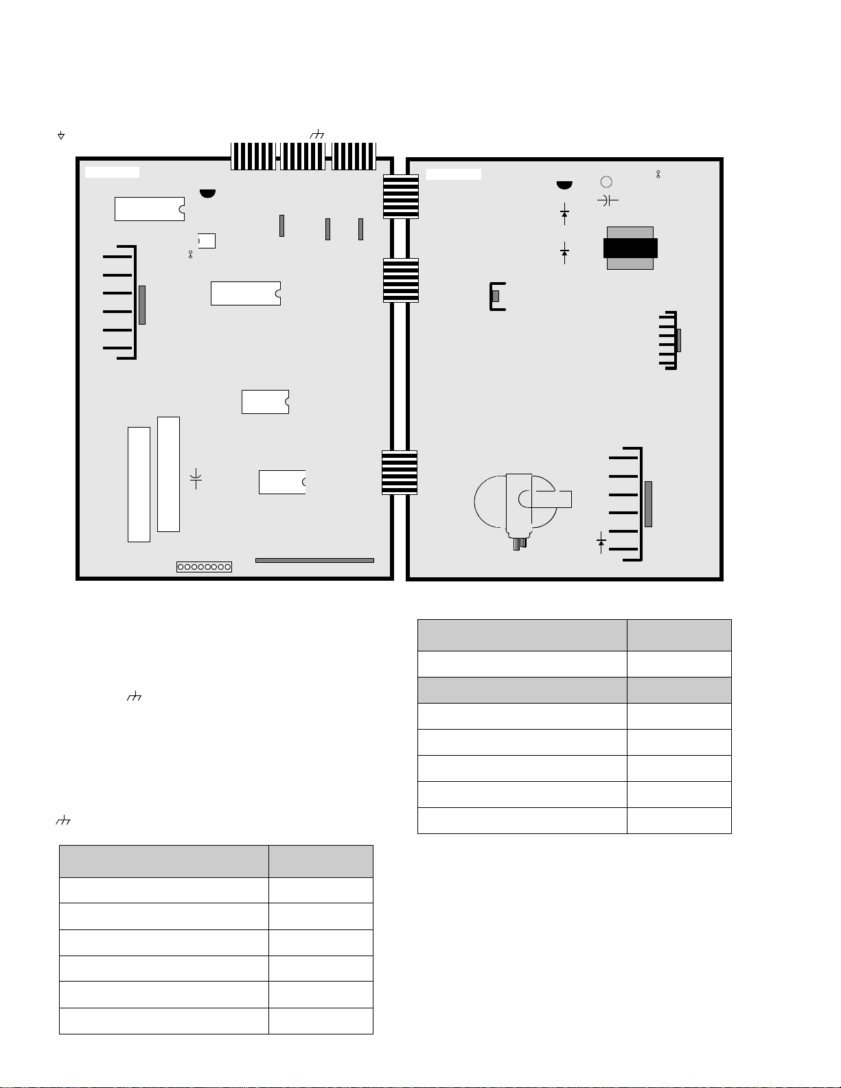
A-BOARD
IC2301
IC001
T
U
N
E
R
T
U
N
E
R
L008
Q002
IC002
+
C3023
-
TP
IC881
IC101
IC1801
IC3001
A/V REAR INPUTS
18
IC882
IC883
D-BOARD
Q804
D751
L826
L824
+
C840
D827
D825
T801
Q801
Q551
D511
MOMENTARILY CONNECT A JUMPER FOR ENTERING SERVICE MODE (TP8 to COLD GND)
140.0V B+ Voltage Confirmation
1. Set the Bright and the Picture to Minimum by
using the Picture Menu.
2. Connect the DVM between
ground ( ).
3. Confirm that B+ voltage is 140.0V ± 1.5V. This
(+ side) and cold
TPP17
LOCAT ION (D-Board) VOLTAGE
TPD7
(by D511)
220V 220.0V ± 9.0V
LOCAT ION (A-Board) VOLTAGE
TP A 6
(by IC883)
MAIN 12V 12.0V ± 0.5V
voltage supplies B+ to the Horizontal Output &
Flyback circuits.
Source Voltage Chart
120V AC line input. Se t the Bright and the Picture to
Minimum by using th e Picture Menu. Use cold ground
) for the (-) lead of the DVM.
(
TP A 7
TPA8
TPA16
TP A 18
(by IC3001)
(by L008)
(by Q002)
(by C3023)
MAIN 9V 9.0V ± 0.5V
MAIN 5V 5.0V ± 0.3V
STBY 3.3V 3.3V ± 0.2V
BTL 30V 32.0V ± 2.0V
.
LOCATION (D-Board) VOLTAGE
TPP17
TPP25
TPP19
(by D825)
(by D827)
(by Q804)
+B2 140.0V ± 1.5V
9V 9.0V ± 1.5V
15V 15.0V ± 2.0V
Adjust Picture Menu for normalized video adjustments.
High Voltage Check
1. Select an active TV channel and confirm that
horizontal is in sync.
2. Adjust Brightness and Picture using Picture Icon
menu so video just disappears.
TPP20
TPP21
(by C840)
(by L826)
15V (VER.) 15.0V ± 1.5V
-15V (VER.) -15.0V ± 1.5V
3. Confirm B+ 140.0V is within limit.
4. Using a high voltage meter confirm that the High
Voltage is 31.0kV ± 1.0kV.
TPP22 (
by L824
) SOUND 32.5V ± 2.0V
- 12 -
Serviceman Mode (Electronic Controls)
This Receiver has electronic technology using the I²C Bus Concept. It performs as a control function and it
replaces many mechanical controls. Instead of adjusting mechanical controls individually, many of the control
functions are now performed by using “On Screen Display Menu”. (The Serviceman Adjustment Mode.)
Note: It is suggested that the tec hnician reads all the way through and understand the following proc edure for
Entering/Exiting th e Serviceman Adjustment Mode; then proce ed with the instructi ons working with th e
Receiver. When becoming f ami li ar with t he procedure, the Fl ow Chart for Servicema n Mod e may be used
as a quick guide.
Quick Entry to Serviceman Mode:
At times when minor adjustments need to be done to the electronic controls, the method of Entering the
serviceman Mode without removal of the cabinet back is as follows using the Remote Control:
1. Select SET-UP icon and select CABLE mode.
2. Select TIMER icon and set SLEEP time for 30 Min.
3. Press ACTION button 3 times to exit menus.
4. Tune to the Channel 124.
5. Adjust VOLUME to minimum ( 0) .
6. Press the VOL button (decrease) on Receiver. Red “CHK” appears in upper corner.
To toggle between Aging and Serviceman modes:
While the “CHK” is displayed on the left top corner of the CRT, pressing the Action and the Volume Up buttons
on the Receiver simultaneously will toggle between the modes. Red “CHK” for Serviceman and yellow “CHK” for
Aging.
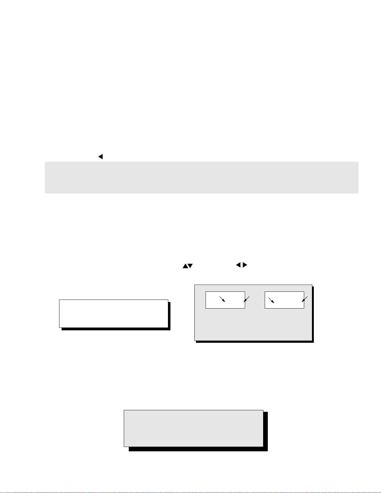
7. Press the Power Bu tton on the Remote Control to select one of the Serviceman Adjustment Modes.
1) B= Serviceman VCJ SUB-DATA ADJUSTEMENT.
2) C= Serviceman VCJ CUT-OFF ADJU STMENT.
3) D= Serviceman GEOMETRY ADJUSTMENT.
4) M= Serviceman MTS ADJ U S TM EN TS .
5) P= Service man PIP ADJUSTMENT.
6) S= Serviceman S OPTION ADJUSTMENTS.
7) X = Serviceman X OPTION ADJ U S TM ENT.
8) E = Serviceman E OPTION ADJ U S TM ENTS
9) “CHK” = Normal operation of CHANNEL and VOLUME .
Note: Only the appli c able settings for
b
32 B 0 2 215 C 0
a
b
a
the Receiver serviced will be
available (See
a
in Fig. 20).
An address Menu appears in the right
hand corner of the screen
Figure 20. Serviceman Mode Menu Adjustments.
Exiting the Serviceman Mode:
Press the Action and the Power buttons on the Receiver simultaneously for at least 2 seconds.
THE RECEIVER EXITS SERVICEMAN MODE.
The Receiver momentarily shuts off; then comes back on tuned to channel 3 with a preset level of sound.
Any programmed channels, channels caption data and some others user defined settings will be erased.
IMPORTANT NOTE:
Always Exit the Serviceman Mode
Following Adjustments.
- 17 -
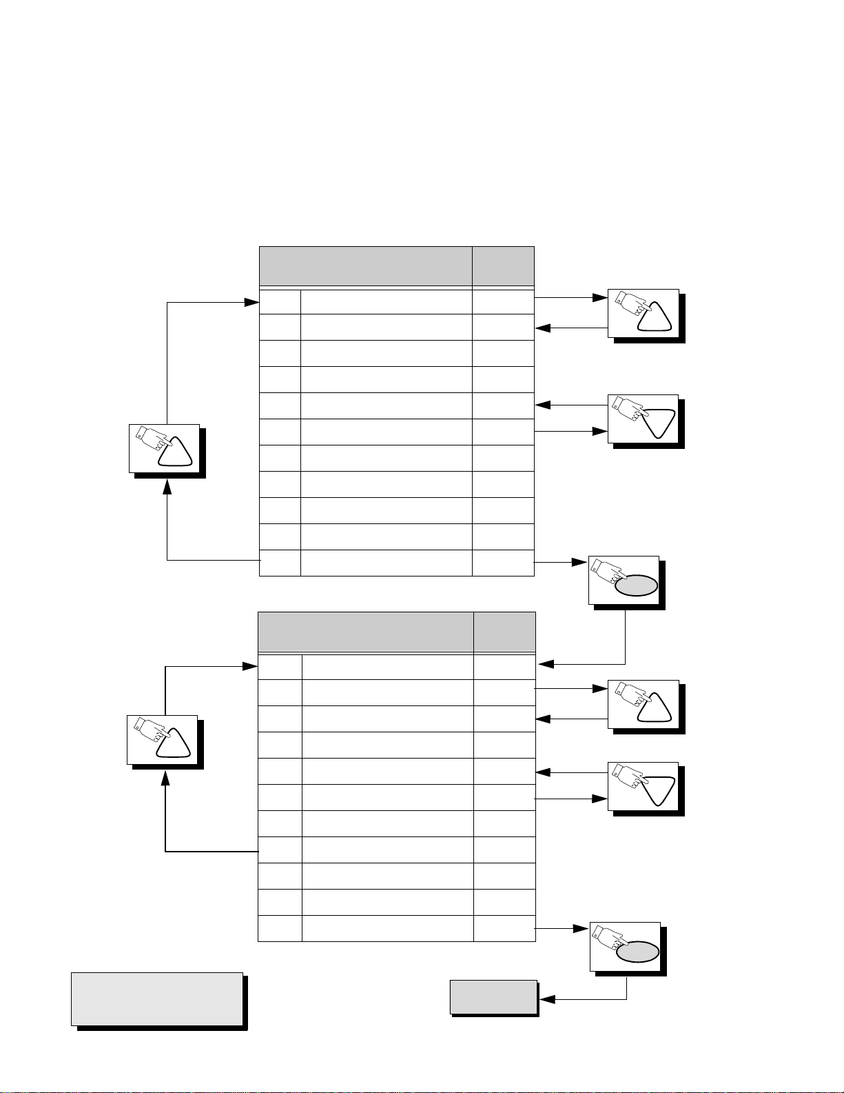
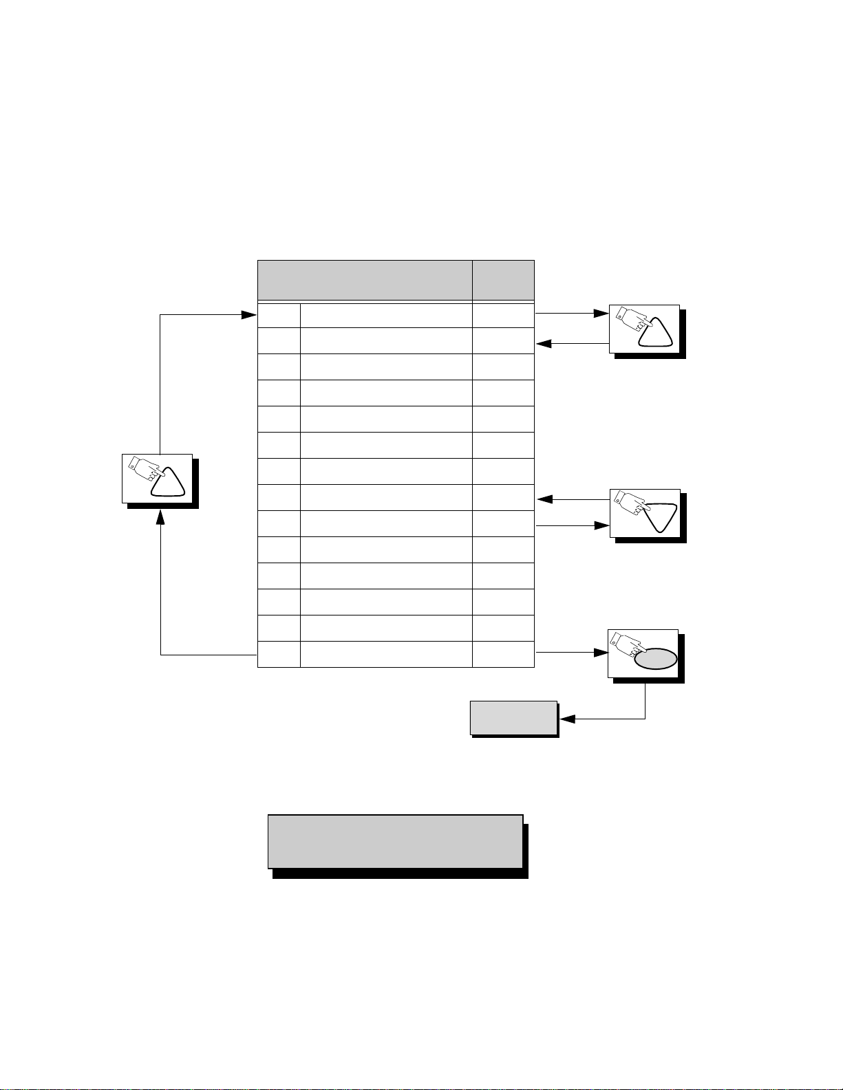
Press the Power Button on the Remote Control to select the Serviceman Adjustment .
For Adjustments:
1.Press Channel Up/Down on the
Remote Control to select one of
the available Se rvice Adjustments
(a in Fig. 20).
Note: Write Down the original
value set (b in
Fig. 20
) for
each address before
modifying anything. It is
easy to erroneously adjust
the wrong item.
2.Press Volume Up/Down on the
Remote Control to adjust the
level of the selected Service
Adjustment (b in Fig. 20).
CH
Sub-Data Adjustment
B00 SUB-COLOR 31
B01 SUB-TINT 40
B02 SUB-BRIGHTNESS 40
B03 SUB-CONTRAST 16
B04 SUB-TINT VIDEO 16
B05 SUB-COLOR VIDEO 22
B06 SUB-TINT COMP 63
B07 SUB-COLOR COMP 28
B08 SUB SHARP TV/VIDEO 10
B09 SUB SHARP S-VHS/COMP 17
B0A SUB-CONTRAST FIXED 15
Cut-Off Adjustment
Default
Level
Default
Level
CH
CH
PW
CH
IMPORTANT NOTE:
Always Exit the Serviceman
Mode Followi ng Adjustments.
C00 CUT-OFF R 128
C01 CUT-OFF G 128
C02 CUT-OFF B 128
C03 BRIGHTNESS 31
C04 G DRIVE 64
C05 B DRIVE 64
C06 DRIVE C TEMP 8
C07 CONT C TEMP 5
C08 CUTOFF R COMP 112
C09 CUTOFF G COMP 114
C0A CUTOFF B COMP 103
To D Items.
- 18 -
CH
CH
PW

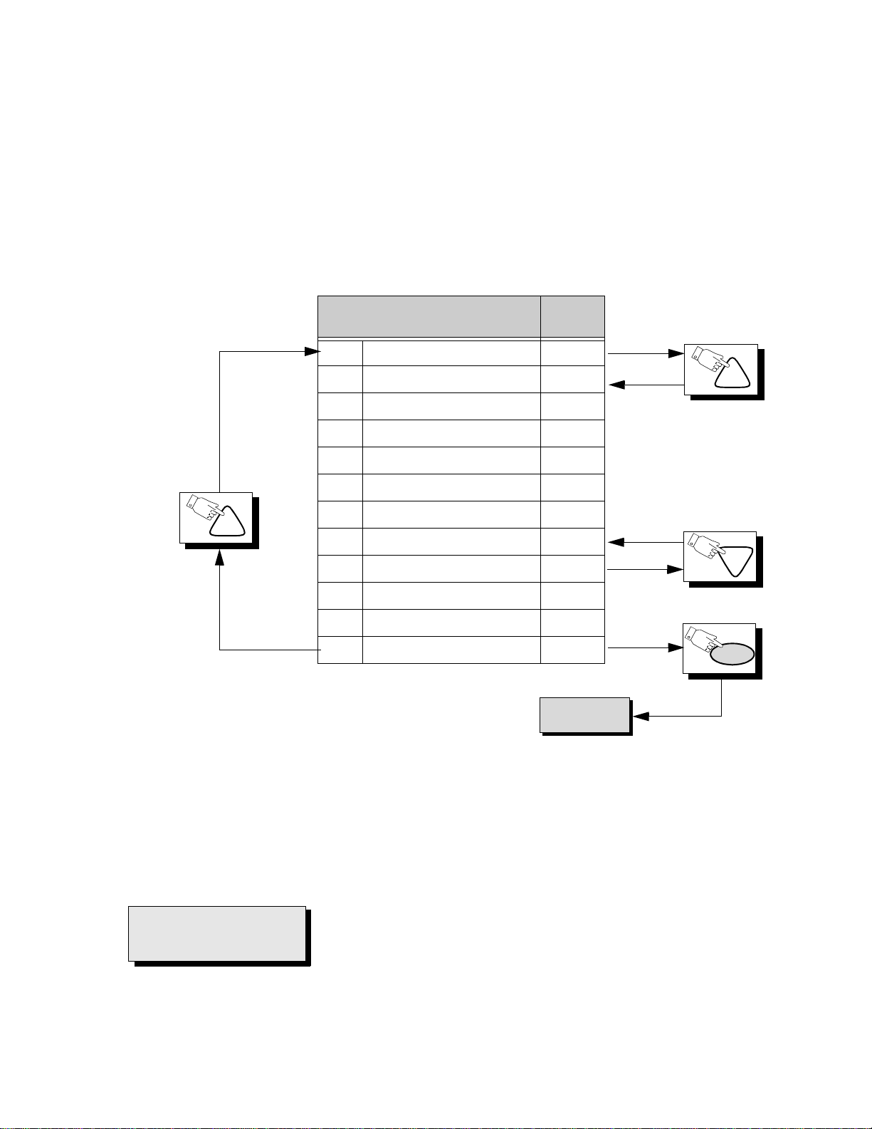
Press the Power Button on the Remote Control to select the Serviceman Adjustment
For Adjustments:
1.Press Channel Up/Down on the
Remote Control to select one of
the available Se rvice Adjustments
(a in Fig. 20).
Note: Write Down the original
value set (b in
Fig. 20
) for
each address before
modifying anything. It is
easy to erroneously adjust
the wrong item.
2.Press Volume Up/Down on the
Remote Control to adjust the
level of the selected Service
Adjustment (b in Fig. 20).
CH
Geometry Adjustments
D00 H POSI TION 13
D01 V SIZE 37
D02 V S CORRECTION 5
D03 V LIN CORRECTION 8
D04 E/W TRAPEZIUM 9
D05 V AGC 1
D06 V POSITION 1
D07 V CENTERING 65
D08 V CENTERING DAC SW 0
D09 V-BLK START 12
D0A V-BLK STOP 14
D0B EW CORNER 6
D0C EW PARABOLA 11
D0D H WIDTH 20
Default
Level
CH
CH
D0E OSD POSITION 90
CH
Note: Some adjustment modes may not be
available in some formats.
M00 INPUT LEVEL 33
M01 LOW-LEVEL SEPARATION 6
M02 HIGH-LEVEL SEPARATION 25
MTS Adjustment
IMPORTANT NOTE:
Always Exit the Serviceman
Mode Following Adjustments.
- 19 -
PW
Default
Level
PW
To P Items.
Press the Power Button on the Remote Control to select the Serviceman Adjustment
e
e
e
For Adjustments:
1.Press Channel Up/Down on the
Remote Control to select one of
the available Servic e Adjustments
(a in Fig.20).
CH
Note: Write Down the original
value set (b in
Fig. 20
) for
each address before
modifying anything. It is
easy to erroneously adjust
the wrong item.
PIP Adjustment
P00 PIP COLOR 53
P01 PIP TINT 64
P02 PIP BRIGHTNESS 11
P03 PIP CONTRAST 58
P04 PIP POS V_TOP 26
P05 PIP POS V_BOTTOM 143
P06 PIP POS H_LEFT 10
P07 PIP POS H_RIGHT 101
P08 PIP POS 26
Default
Level
2.Press Volume Up/Down on th
Remote Control to adjust th
level of the selected Servic
Adjustment (b in Fig. 20).
CH
CH
P09 PIP POS 160
P0A PIP POS 10
P0B PIP POS 116
P0C N/A N/A
P0D PIP YDELAY 4
To S Items.
Note: Some adjustme nt mode s ma y n ot be
available in some formats.
PW
- 20 -
Press the Power Button on the Remote Control to select the Serviceman Adjustment
e
e
e
For
Adjustments:
1.Press Channel Up/Down on the
Remote Control to select one of
the available Servic e Adjustments
(a in Fig.20).
Note: Write Down the original
value set (b in
Fig. 20
) for
each address before
modifying anything. It is
easy to erroneously adjust
the wrong item.
2.Press Volume Up/Down on th
Remote Control to adjust th
level of the selected Servic
Adjustment (b in Fig. 20).
CH
OPTIONS Adjustment
S00 ABL GAIN 3
S01 ABL POINT 3
S02 RGB BRIGHTNESS 3
S03 RGB GAMMA 1
S04 GAMMA 1
S05 VSM-G 0
S06 BS POINT 3
S07 CLOCK ADJUST 128
S08 CAP DIGITAL FIL 0
S09 CAP SCROLL 1
S0A RGB MATRIX 6
S0B RGB MATRIX YUV 5
Default
Level
To X Items.
CH
CH
PW
IMPORTANT NOTE:
Always Exit the Serviceman
Mode Following Adj ustments.
- 21 -

Press the Power Button on the Remote Control to select the Serviceman Adjustment
For Adjustments:
1.Press Channel Up/Down on the
Remote Control to select one of
the available Se rvice Adjustments
(a in Fig. 20).
Note: Write Down the original
value set (b in
Fig. 20
) for
each address before
modifying anything. It is
easy to erroneously adjust
the wrong item.
2.Press Volume Up/Down on the
Remote Control to adjust the
level of the selected Service
Adjustment (b in Fig. 20).
CH
X Option Adjustment
X00 V ENHANCER 3
X01 V ENH NL 1
X02 H PEAKING GAIN 2
X03 V CORING 1
X04 C TRAP GAIN 0
X05 GEO MAG CEN 179
X06 GEO MAG GAIN 10
X07 H LOCK 1
X08 H LOCK L 70
X09 H SEPA 1L 313
X0A H SEPA 2L 266
X0B H LOCK W 0
X0C H LOCK L 70
X0D H SEPA 1WL 313
Default
Level
CH
CH
CH
X0E H SEPA 2WL 266
E Option Adjustment
E00 SURROUND EFFECT 3
E01 BBE LOW 4
E02 BBE HIGH 6
Default
Level
To B Items.
- 22 -
PW
PW
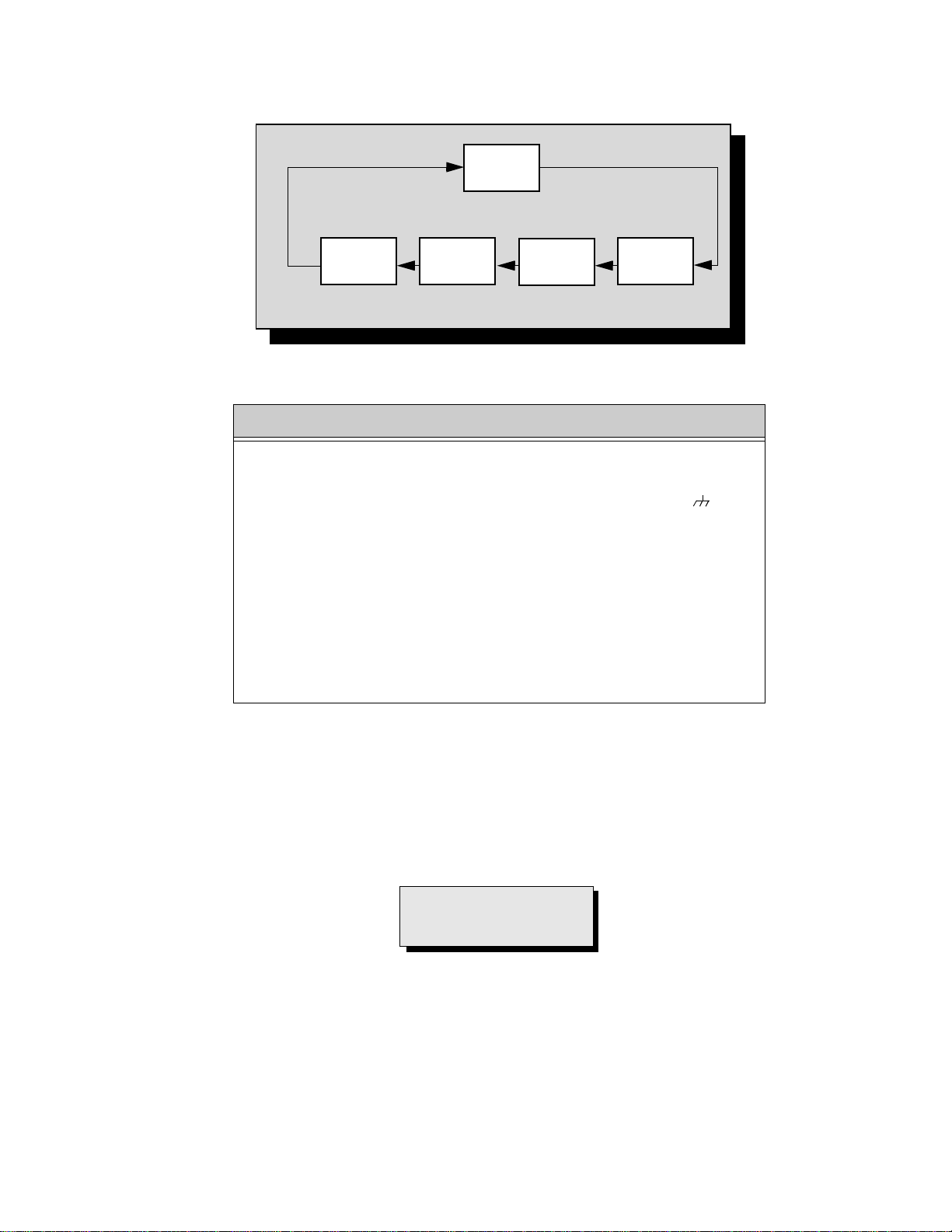
To Check Purity:
Press the Recall Button on the Remote Control when in Servic eman Mode ( red “CHK” is displa yed) to enter the
Purity Field Check Mode.
NORMAL
SCREEN
Press Recall again to select desired field.
BLUE
SCREEN
GREEN
SCREEN
RED
SCREEN
WHITE
SCREEN
Figure 21. Purity Check Field Mode.
Helpful Hints
Entering Serviceman Mode (Back-Open Method)
1. While the Receiv er is ON or Puggled a nd operating in Norm al Mode,
momentarily short test point FA 1 (TP8) to Cold Ground ( ) FA2
(TP3) A-Board.
The Receiver enters the Aging Mode
Yellow letters “CHK” appear in the upper left corner of the CRT.
(The Volume Up/Down will adjust rapidly).
2. Simultaneously press the Action and the Volume Up buttons on the
Receiver Control Panel.
The Receiver enters the Serviceman Mode.
The letter in “CHK” turn red.
(The Volume Up/Down will adjust normally).
(All customer controls are set to nominal level).
.
IMPORTANT NOTE:
Always Exit the Serviceman
Mode Following Adjustments.
- 23 -
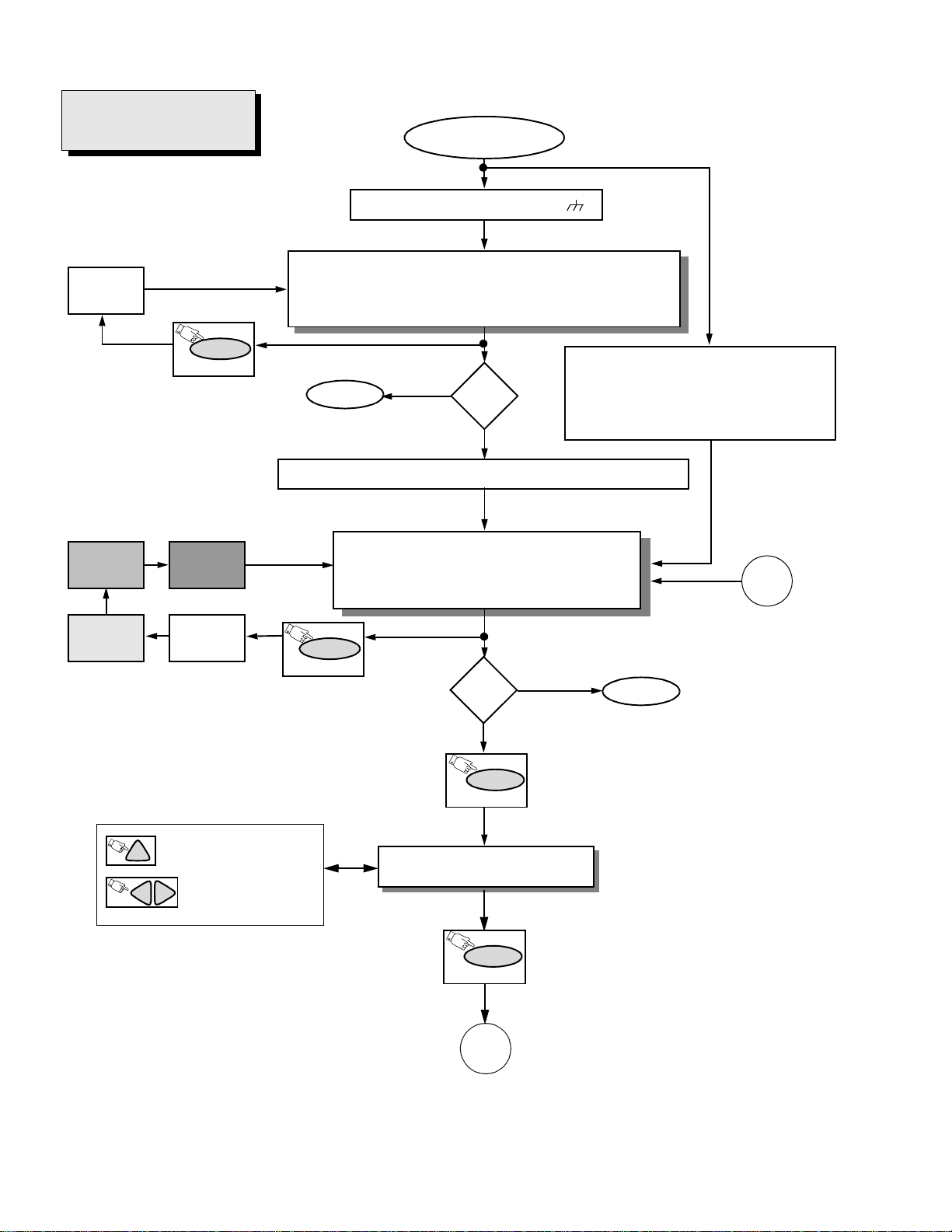
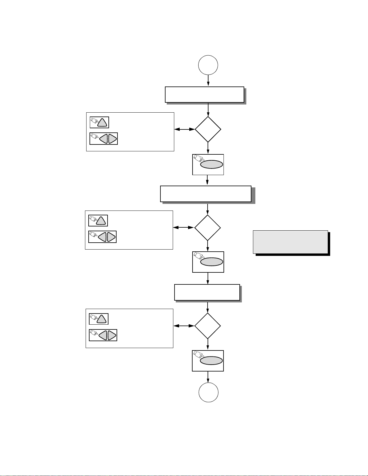
Instructional Flow Chart for Serviceman Mode
IMPORTANT NOTE:
Always Exit the Serviceman
Mode Following Adjustments.
WHITE
SCREEN
NORMAL MODE
Momentarily short FA1 to FA2 .
AGING MODE
• Yellow “CHK” appears in upper left corner of screen.
• Volume Up/Down operate rapidly.
• Customer C ontrols are set to nominal level.
GREEN
SCREEN
RED
SCREEN
RECALL
(ON REMOTE)
BLUE
SCREEN
WHITE
SCREEN
QUICK ENTRY TO SERVICEMAN MODE
• Select CABLE Mode.
•Set SLEEP time for 30 Min.
• Tune to Channel 124.
• Adjust Volume to minimum.
• Press VOL DOWN On Receiver.
EXIT
N
Adj.
needed?
Y
Press Action + Volume Up Simultaneously (ON Receiver)
SERVICEMAN MODE
• “CHK” turns red.
• Volume Up/Down operate normally.
• Customer Controls are set to nom in al level.
RECALL
(ON REMOTE)
Adj.
needed?
Y
POWER
(ON REMOTE)
N
EXIT
Press Action and Power on the Receiver
simultaneously for at least 2 seconds.
C
ON REMOTE CONTROL TO
CH
SELECT ADJUSTMENT
ON REMOTE TO ADJUST
VOL
VOL
THE LEVEL
SUB-DATA ADJUS TMENTS.
B ITEMS.
POWER
(ON REMOTE)
A
Figure 22. Flow Chart for Serviceman Mode.
- 24 -
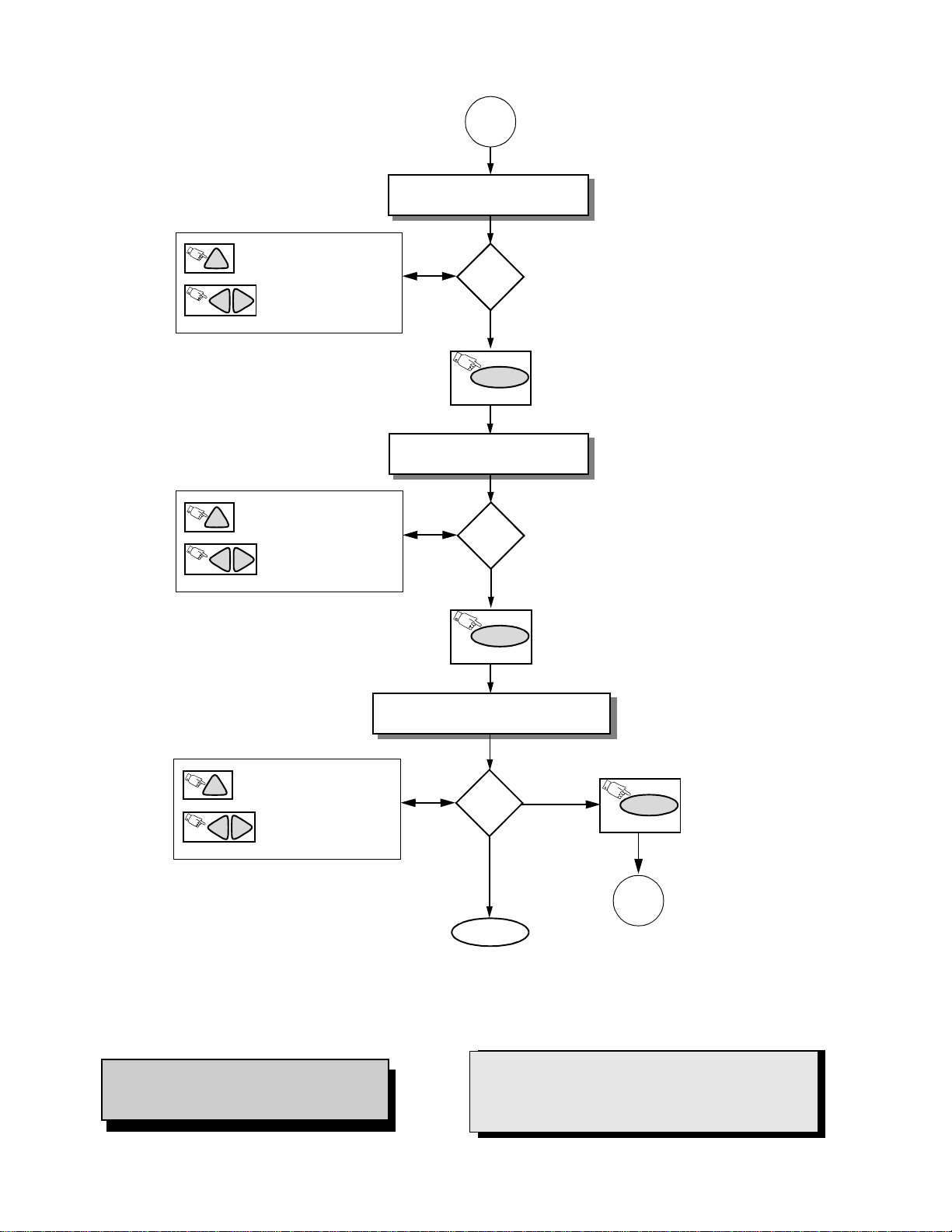
Instructional Flow Chart f or Serviceman Mode - Continued
A
CUT-OFF ADJUSTMENTS.
C ITEMS.
ON REMOTE CONTROL TO
CH
SELECT ADJUSTMENT
ON REMOTE TO ADJUST
VOL
VOL
THE LEVEL
ON REMOTE CONTROL TO
CH
SELECT ADJUSTMENT
ON REMOTE TO ADJUST
VOL
VOL
THE LEVEL
PINCUSHION ADJUSTMENTS.
Y
Adj.
needed?
POWER
(ON REMOTE)
D ITEMS.
Y
Adj.
needed?
N
N
IMPORTANT NOTE:
Always Exit the Serviceman
Mode Following Adjustments.
ON REMOTE CONTROL TO
CH
SELECT ADJUSTMENT
ON REMOTE TO ADJUST
VOL
VOL
THE LEVEL
Figure 23. Flow Chart for Serviceman Mode (cont).
POWER
(ON REMOTE)
MTS ADJUSTMENTS.
M ITEMS.
Adj.
Y
needed?
N
POWER
(ON REMOTE)
B
- 25 -
Instructional Flow Chart for Serviceman Mode - Continued
B
PIP ADJUSTMENTS.
P ITEMS.
ON REMOTE CONTROL TO
CH
SELECT ADJUSTMENT
ON REMOTE TO ADJUST
VOL
VOL
THE LEVEL
ON REMOTE CONTROL TO
CH
SELECT ADJUSTMENT
ON REMOTE TO ADJUST
VOL
VOL
THE LEVEL
OPTIONS ADJUSTMENTS.
Adj.
Y
needed?
N
POWER
(ON REMOTE)
S ITEMS.
Adj.
Y
needed?
N
ON REMOTE CONTROL TO
CH
SELECT ADJUSTMENT
ON REMOTE TO ADJUST
VOL
VOL
THE LEVEL
Figure 24. Flow Chart for Serviceman Mode (cont).
Note: Some adjustments m od es may not be
available in some models depending
on available options .
POWER
(ON REMOTE)
COMB-FILTER ADJUSTMENTS.
X ITEMS.
Adj.
Y
N
needed?
N
EXIT
Press Action and Power on the Receiver
simultaneously for at least 2 seconds.
IMPORTANT NOTE:
Always Exit the Serv iceman Mode
Following Adjustments.
POWER
(ON REMOTE)
C
- 26 -
 Loading...