

Panasonic CT-36SX12U, CT-36SX12, CT-32SX12U, CT-32SX12 Operating Instructions Manual
asonlc o
Color Television
Operating Instructions
CT-32SX12
CT-32SX12U
CT-36SX12
CT-36SX12 U
For assistance, please call: 1-800-211-PANA (7262) or TQB2AA0383-0 20404
send e-mail to: consumerproducts@panasonic.com (USA only) PRINTED IN USA
WARNING: Toreducemeriskofelectricshockdonotremovecoverorback.
Nouser-serviceablepartsinside.Referservicingtoqualifiedservicepersonnel.
The lightning flash with arrow
head within a tdengle is
intended to tell the user that
pads inside the product are a
risk of electhc shock to
parsons.
The exclamaUon point within a
triangle is intended to tell the
user that important operating
and servicing instructions are
in the papers with the
appliance.
WARNING: TO REDUCE THE RISK OF FIRE OR ELECTRIC SHOCK, DO
NOT EXPOSE THIS APPARATUS TO RAIN OR MOISTURE.
I J_J The double insulation symbol (a square within a square) is
intended to alert qualified service personnel to use only
identical replacement parts in this apparatus.
FCC CAUTION: ANY CHANGES OR MODIFICATIONS TO THIS TV
RECEIVER NOT EXPRESSLY APPROVED BY
MATSUSHITA ELECTRIC CORPORATION OF AMERICA
COULD CAUSE HARMFUL INTERFERENCE, WHICH
WOULD VOID THE USER'S AUTHORITY TO OPERATE
THIS EQUIPMENT.
ENVIRONMENTAL NOTICE: THIS PRODUCT UTILIZES BOTH A CATHODE RAY TUBE (CRT) AND
OTHER COMPONENTS THAT CONTAIN LEAD. DISPOSAL OF THESE
MATERIALS MAY BE REGULATED IN YOUR COMMUNITY DUE TO
ENVIRONMENTAL CONSIDERATIONS. FOR DISPOSAL OR RECYCLING
INFORMATION PLEASE CONTACT YOUR LOCAL AUTHORITIES, OR THE
ELECTRONICS INDUSTRIES ALLIANCE: <H'I-rP:flWWW.EIAE.ORG.>
BBH Manufactured under license from BBE Sound, Inc.
Licensed by BBE Sound, Inc. under USP4638258 and 4482866.
High Definition Sound BBE and BBE symbol are registered trademarks of BBE Sound, Inc.
Table of Contents
Congratulations ......................................................... 2
Customer Record ...................................................................... 2
Care and Cleaning ..................................................................... 2
Specifications ............................................................................ 2
Installation .................................................................. 3
Television Location .................................................................... 3
Optional Cable Connections ...................................................... 3
AC Power Supply Cord .............................................................. 3
Cable / Antenna Connection ...................................................... 3
Feature Chart ............................................................ 4
Auto Set Up Menu ...................................................... 5
Optional Equipment Connections ........................... 6
VCR Connection ........................................................................ 6
Front Control Panel ................................................................... 6
Cable Box Connection ............................................................... 7
VCR and Cable Box Connection ............................................... 7
Program Out Connection (PROG OUT) .................................... 8
Amplifier Connection (TO AUDIO AMP) .................................... 8
Digital TV - Set-Top Box or DVD Player Connection ................. 9
Remote Control Operation ..................................... 10
Battery Installation ................................................................... 10
Mode Operational Key Chart .................................................. 11
Programming the Remote ....................................................... 12
Programming With a Code ...................................................... 12
Programming Without a Code ................................................. 12
Component Codes ................................................................... 13
Icon Menu Navigation ............................................. 15
Main Menu Icons ...................................................... 16
Icon Menus .............................................................................. 16
Icon Menu Operation ............................................... 17
Set Up ...................................................................................... 17
Picture ..................................................................................... 19
Timer ....................................................................................... 20
Audio ....................................................................................... 21
Channels ................................................................................. 22
Lock ......................................................................................... 23
V-Chip Menu Operation ........................................... 24
Troubleshooting Chart ............................................ 29
Limited Warranty ..................................................... 30
Customer Services Directory ................................. 32
Index ......................................................................... 33
TABLE OF CONTENTS
Read these instructions completely before operating television.
Contents are subject to change without notice or obligation.
Copyright 2002 by MatsushitaElectricCorporation of America. All rightsreserved.
Unauthorizedcopyinganddistributionisa violationoflaw.
10
CONGRATULATIONS
Congratulations
Your new TV Monitor/Receiver features a solid state chassis that is designed to give you many years of enjoyment, it was
thoroughly tested and tuned at the factory for best performance.
Customer Record
The model and serial number of this product are located on the back of the television. You should note the model and serial
number in the space provided and retain as a permanent record of your purchase. This will aid in identification inthe event
of theft or loss. Product registration for U.S. customers is available at www.prodreg.com/panasonic.
Model
Number
Sedal
Number
Care and Cleaning
Screen (Turn TV Off)
Usea mildsoapsolutionorwindowcleanerwithasoftcleancloth.DO NOT USEABRASIVECLEANERS.
• Avoidexcessive moistureandwipedry.
Note: Do not spray any type of cleaning fluid directly on the screen.
Cabinet and Remote Control
O For cabinetsand remotecontrol,usea softclothdampenedwithwateror a milddetergentsolution.Avoidexcessivemoistureand
wipe dry.
O Donot use benzene,thinnerorotherpetroleumbasedproducts.
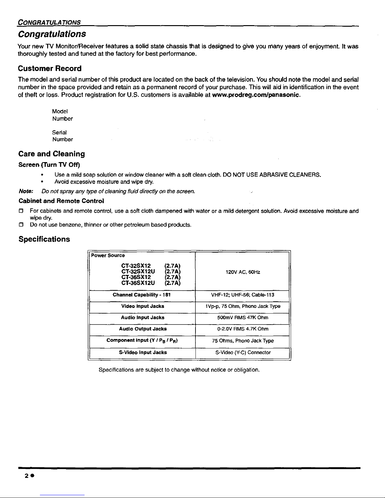
Specifications
Power Source
CT-32SX12 (2.7A)
CT-32SX12U (2.7A) 120v AC, 60Hz
CT-36SX12 (2.7A)
CT-36SX12U (2.7A)
Channel Capability - 181 VHF-12; UHF-56; Cable-113
Video Input Jacks 1Vp-p, 75 Ohm, Phono Jack Type
Audio Input Jacks 500rnV RMS 47K Ohm
Audio Output Jacks 0-2.0V RMS 4.7K Ohm
Component input (Y / P@I PR) 75 Ohms, Phono Jack Type
S-Video Input Jacks S-Video (Y-C) Connector
Specifications are subject to change without notice or obligation.
2e
Installation
Television Location
Follow these recommendations before deciding the location of your television.
O Avoid excessive sunlight or bright lights, including reflections.
[] Keep away from excessive heat or moisture. Inadequate ventilation may cause internal component failure.
[] Fluorescent lighting may reduce remote control transmitting range.
[] Keep away from magnetic equipment, including motors, fans and external speakers.
]NSTALLATION
CAUTION: Use this television receiver only with the cart, stand, tripod, bracket, or table specified by the manufacturer, or
sold with the apparatus. When a cart is used, use caution when moving the cart/apparatus combination to avoid injury from
tip-over, in order to avoid injury to children, never place your television receiver on a piece of fumitura that is capable of
being tilted by a child leaning on it, pulling on it, standing on it, or climbing on it.
CT-32SX12, CT-32SX12U:
CAUTION: These television receivers for use only with PANASONIC TY-32SX31P stand. Use with other carts (or stands) is capa-
ble of resulting in instability causing possible injury.
CT-36SX12, CT-36SX12U:
CAUTION: These television receivers for use only with PANASONIC TY-36SX31P stand. Use with other carts (or stands) is capa-
ble of resulting in instability causing possible injury.
Optional Cable Connections
Shielded audio and video cables should be used between components. For best results:
O Use 75-ohm coaxial shielded cables.
C3 Use appropriate input and output connectors that match your component connectors.
[] Avoid long cables to minimize interference.
AC Power Supply Cord
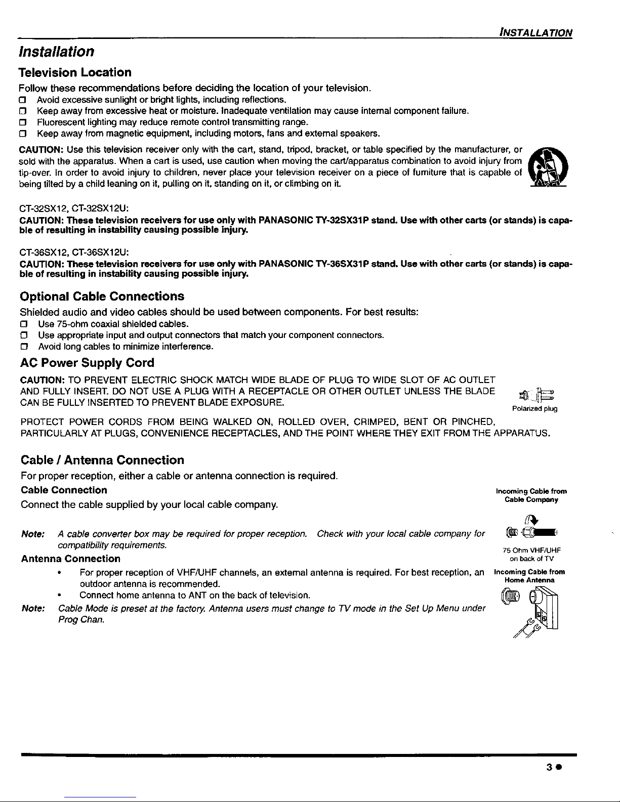
CAUTION: TO PREVENT ELECTRIC SHOCK MATCH WIDE BLADE OF PLUG TO WIDE SLOT OF AC OUTLET
AND FULLY INSERT. DO NOT USE A PLUG WITH A RECEPTACLE OR OTHER OUTLET UNLESS THE BLADE
CAN BE FULLY INSERTED TO PREVENT BLADE EXPOSURE.
Polanzed plug
PROTECT POWER CORDS FROM BEING WALKED ON, ROLLED OVER, CRIMPED, BENT OR PINCHED,
PARTICULARLY AT PLUGS, CONVENIENCE RECEPTACLES, AND THE POINT WHERE THEY EXIT FROM THE APPARATUS.
Cable / Antenna Connection
For proper reception, either a cable or antenna connection is required.
Cable Connection
Connect the cable supplied by your local cable company.
Note: A cable converter box may be required for proper reception. Check with your local cable company for
compatibility requirements.
Antenna Connection
For proper reception of VHF/URF channels, an external antenna is required. For best reception, an
outdoor antenna is recommended.
Connect home antenna to ANT on the back of television.
Note: Cable Mode is preset at the factor_ Antenna users must change to TV mode in the Set Up Menu under
Preg Chan.
Incoming Cable from
Cable Company
75 Ohm VHF/UHF
on back of TV
Incoming Cable from
Home Antenna
3e
FEATURE CHART
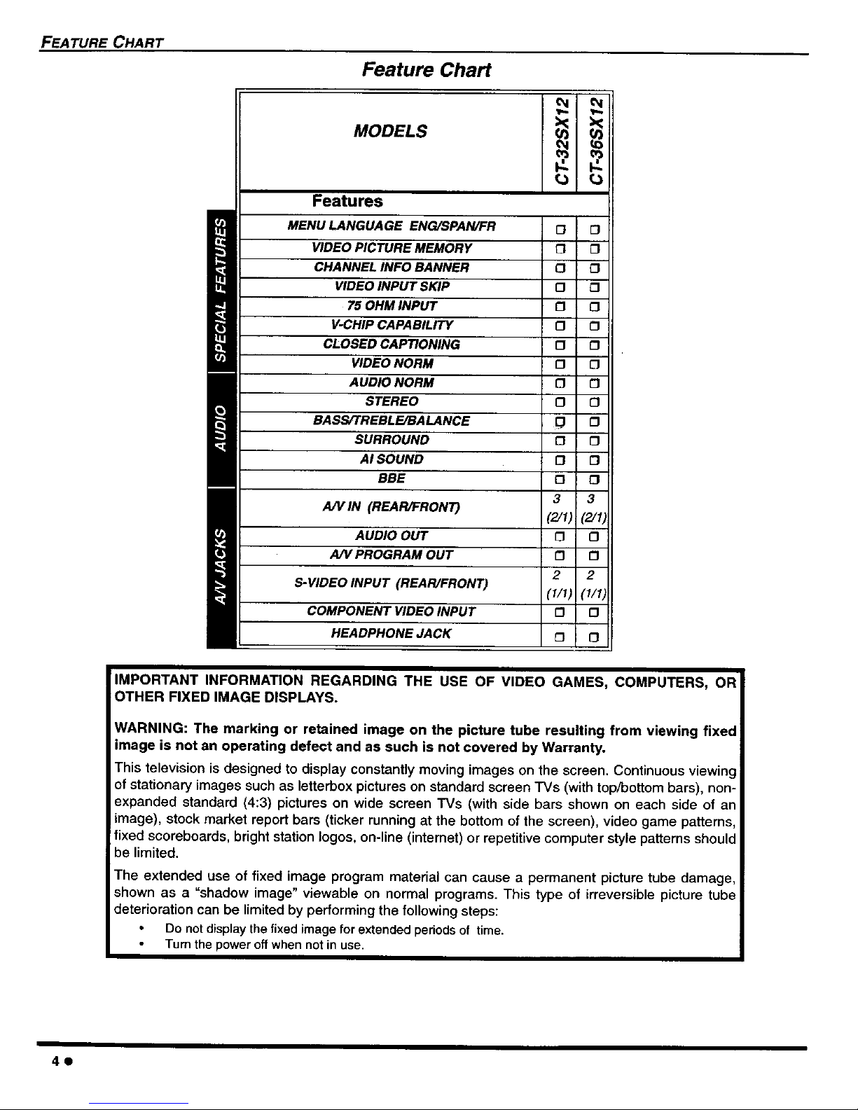
Feature Chart
MODELS
Features
i MENU LANGUAGE ENG/SPAN/FR 0 O
VIDEO PICTURE MEMORY [_ []
CHANNEL INFO BANNER [] £3
VIDEOINPUT SKIP []
75 OHM INPUT [] 0
V-CHIPCAPABILITY [] []
CLOSED CAPTIONING [] £3
VIDEO NORM [] []
AUDIO NORM [] []
STEREO [] []
BASS/TREBLE/BALANCE D []
SURROUND [] []
AI SOUND [] []
BBE 0 []
ALVIN (REAR/FRONT) 3 3
(2/1) (_/I;
AUDIO OUT [] []
AN PROGRAM OUT [] []
S-VIDEO INPUT (REAR/FRONT) 2 2
(I/I) (1/1_
COMPONENT VIDEO INPUT [] []
HEADPHONE JACK [] []
IMPORTANT INFORMATION REGARDING THE USE OF VIDEO GAMES, COMPUTERS, OR
OTHER FIXED IMAGE DISPLAYS.
WARNING: The marking or retained image on the picture tube resulting from viewing fixed
image is not an operating defect and as such is not covered by Warranty.
This television is designed to display constantly moving images on the screen. Continuous viewing
of stationary images such as letterbox pictures on standard screen TVs (with top/bottom bars), non-
expanded standard (4:3) pictures on wide screen TVs (with side bars shown on each side of an
image), stock market report bars (ticker running at the bottom of the screen), video game patterns,
fixed scoreboards, bright station Iogos, on-line (intemet) or repetitive computer style patterns should
be limited.
The extended use of fixed image program material can cause a permanent picture tube damage,
shown as a "shadow image" viewable on normal programs. This type of irreversible picture tube
deterioration can be limited by performing the following steps:
Do not display the fixed image for extended periods of time.
Turn the power off when not in use.
4e
AUTO SET UP MENU
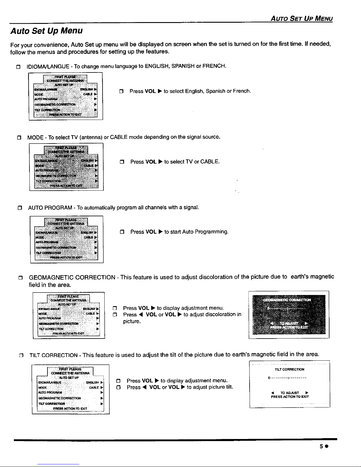
Auto Set Up Menu
For your convenience, Auto Set up menu will be displayed on screen when the set is turned on for the first time. if needed,
follow the menus and procedures for setting up the features.
£3 IDIOMA/LANGUE - To change menu language to ENGLISH, SPANISH or FRENCH.
O Press VOL • to select English, Spanish or French.
O MODE - To select TV (antenna) or CABLE mode depending on the signal source.
£3 Press VOL • to select TV or CABLE.
£3 AUTO PROGRAM - To automatically program all channels with a signal.
£3 Press VOL • to start Auto Programming.
(3 GEOMAGNETIC CORRECTION -This feature is used to adjust discoloration of the picture due to earth's magnetic
field in the area.
O Press VOL • to display adjustment menu.
£3 Press < VOL or VOL • to adjust discoloration in
picture.
TILT CORRECTION - This feature is used to adjust the tilt of the picture due to earth's magnetic field in the area.
; i IFIRS'lrP,,EAS_i
_.TCORRm ; •
_'ro SXIT
O Press VOL • to display adjustment menu.
£3 Press • VOL or VOL • to adjust picture tilt.
TILT CORRECTION
0......... I .........
• TO ADJUST •
PRESS ACTION TO EXIT
5e
OPTIONAL EQUIPMENT CONNECTIONS
Optional Equipment Connections
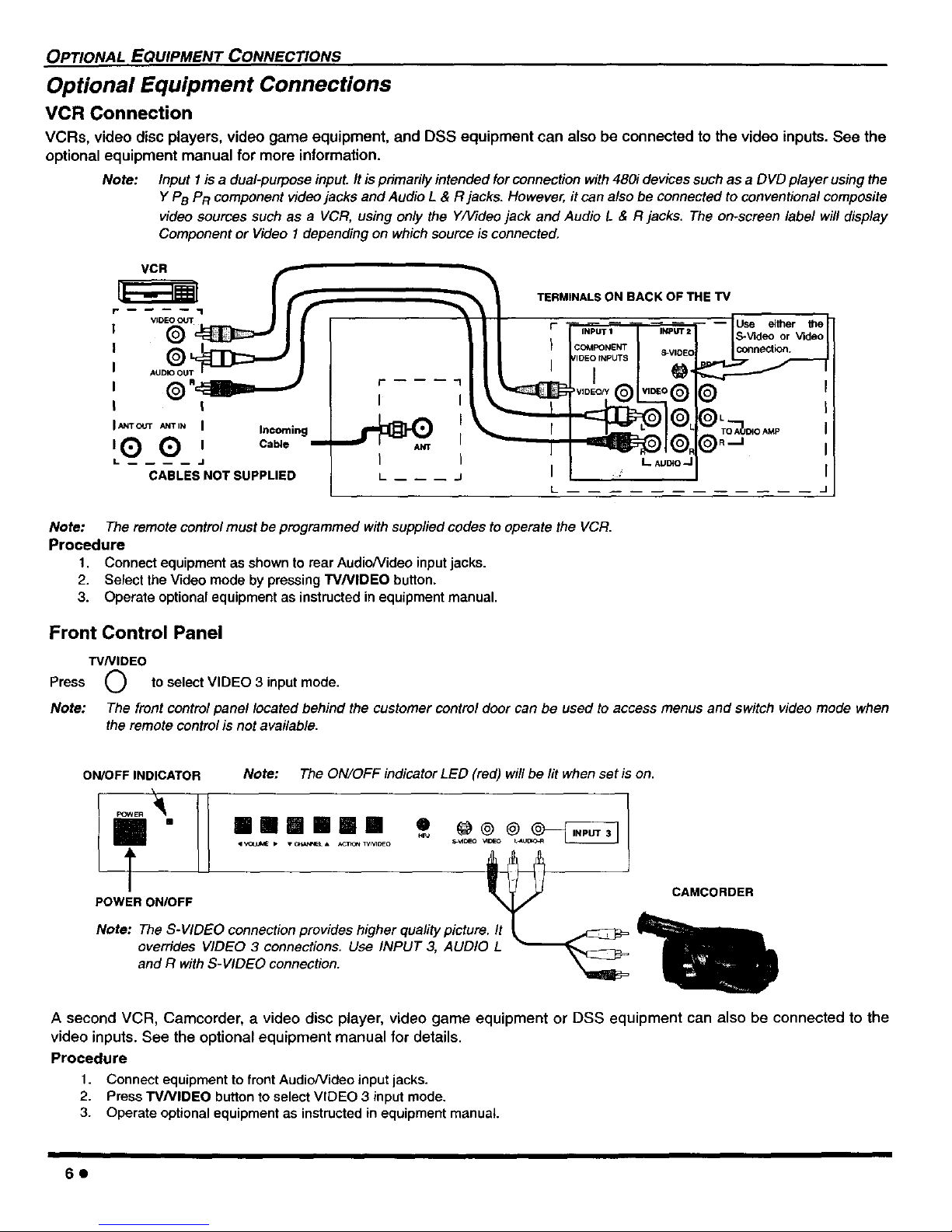
VCR Connection
VCRs, video disc players, video game equipment, and DSS equipment can also be connected to the video inputs. See the
optional equipment manual for more information.
Note: Input 1 is a dual-purpose input. It is primarily intended for connection with480i devices such as a DVD player using the
Y PB PR component video jacks and Audio L & R jacks. However, it can also be connected to conventional composite
video sources such as a VCR, using only the Y/Video jack and Audio L & R jacks, The on-screen label will display
Component or Video I depending on which source is connected,
! I I
,L_'_ f'_l i _e -- I
L J I I
CABLES NOT SUPPLIED L __ -- __ J I
TERMINALS ON BACK OF THE "IV
INPUT 1
CC_MPONENT
_'IDEO INPUTS
I
) VIDEO/Y _
INPt.rr 2
S-VIDEC
O'
VIDEO 0
L Auc4o,J
-- Use either the
S-Video,_orVideo
I L I
i To'_u,=o,_ I
O I
L .............
Note: The remote control must be programmed with supplied codes to operate the VCR.
Procedure
1, Connect equipment as shown to rear AudioNideo input jacks.
2. Select the Video mode by pressing TV/VIDEO button.
3. Operate optional equipment as instructed in equipment manual.
Front Control Panel
W/VIDEO
Press (_ to select VIDEO 3 input mode.
Note: The front control panel located behind the customer control door can be used to access menus and switch video mode when
the remote control is not available.
ON/OFF INDICATOR Note: The ON/OFF indicator LED (red) wiflbe lit when set is on.
I " II aurelian
Note: The S-VIDEO connection provides higher quality picture. It _
overrides VIDEO 3 connections. Use INPUT 3, AUDIO L _'_-_--FJ=
and R with S-VIDEO connection.
CAMCORDER
A second VCR, Camcorder, a video disc player, video game equipment or DSS equipment can also be connected to the
video inputs. See the optional equipment manual for details.
Procedure
1. Connect equipment to front AudioNideo input jacks.
2. Press W/VIDEO button to select VIDEO 3 input mode.
3. Operate optional equipment as instructed in equipment manual.
60
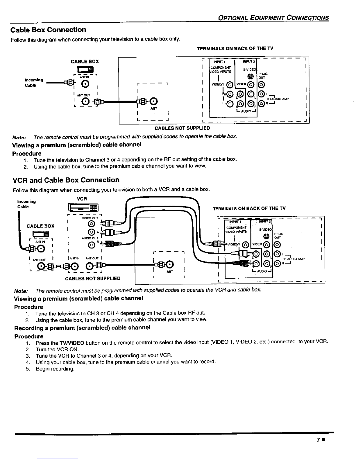
Cable Box Connection
Follow this diagram when connecting your television to a cable box only.
OP_ONAL EQUIPMENT CONNEC_ONS
TERMINALS ON RACK OF THE TV
CABLE BOX
ANT_N
Incoming _ ICable _) I
I ANT OUT I
I.
I I
I
I I
L -- -- i J
iNPtr_ 1 _2
S-VIDEO
nDEO INPUTS
I I
@ @
,
I
I L ^u_o_I I
L -J
CABLES NOT SUPPLIED
Note: The remote control must be programmed with supplied codes to operate the cable box.
Viewing a premium (scrambled) cable channel
Procedure
1. Tune the television to Channel 3 or 4 depending on the RF out setting of the cable box.
2. Using the cable box, tune to the premium cable channel you want to view.
VCR and Cable Box Connection
Follow this diagram when connecting your television to both a VCR and a cable box.
VCR
Incoming
;able
TERMINALS ON BACK OF THE TV
CABLES NOT SUPPLIED
I
I
J
L
pROG
OUT
I
J
Note: The remote control must be programmed with supplied codes to operate the VCR and cable box.
Viewing a premium (scrambled) cable channel
Procedure
1. Tune the television to CH 3 or CH 4 depending on the Cable box RF out.
2. Using the cable box, tune to the premium cable channel you want to view.
Recording a premium (scrambled) cable channel
Procedure
1. Press the W/VIDEO button on the remote control to select the video input (VIDEO 1, VIDEO 2, etc.) connected to your VCR.
2. TumtheVCR ON.
3. Tune the VCR to Channel 3 or 4, depending on your VCR.
4. Using your cable box, tune to the premium cable channel you want to record.
5. Begin recording.
7o

OPTIONAL EQUIPMENT CONNECTIONS
Program Out Connection (PROG OUT)
To use the television audio and video with optional equipment, connect the PROG OUT and TO AUDIO AMP connections on the back of
the television.
Notes:
When a component input video signal is connected to Video t (Y, PB, PR ) terminals, and the 73/main picture is Component, the Program
output video will be luminance signal (no color).
When S-Video input signal is used for TV main picture, the Program output video signal will be luminance signal (no color).
CONNECTIONS ON BACK OF TV
7
VIDEO INPUTS S" DE(
• J
,
CABLES NOT SUPPLIED
MONITOR VCR
Procedure
1. Connect optional equipment to PROG OUT and TO AUDIO AMP terminals.
2. PROG OUT terminal display isthe same as onscreen display.
3. See optional equipment manual for further instructions for recording and monitoring.
Amplifier Connection (To Audio Amp)
Connect to an external audio amplifier input for listening to a stereo system.
Note: TO AUDIO AMP terminals cannot be connected directly to external speakers.
Audio Adjustments
1. Select TV SPEAKERS ON from AUDIO menu.
2. Set amplifier volume to minimum.
3. Adjust TV volume to desired level.
4. Adjust amplifier volume to match the TV.
5. Select TV SPEAKERS OFF&VAO from AUDIO menu.
6. Volume, mute, bass, treble and balance are now controlled from the TV.
Note: In OFF&FAO the volume is controlled by the extema/ amplifier.
F
I
I
I
I
I
I
I
L
TERMINALS ON SACK OF TV
L AUDIO ,.J
External Amplifier
CABLES NOT SUPPLIED
80
OPTIONAL EQUIPMENT CONNECTIONS
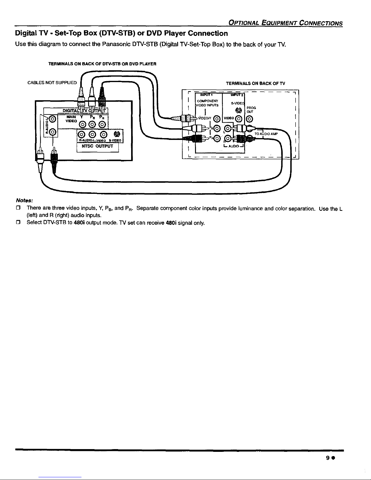
Digital TV - Set-Top Box (DTV-STB) or DVD Player Connection
Use this diagram to connect the Panasonic DTV-STB (Digital W-Set-Top Box) to the back of your "IV.
TERMINALS ON BACK OF DTV-S'rB OR DVD pLAYER
CABLES NOT SUPPLIED
NTSC OUTPUT
COMPONENT
TERMINALS ON BACK OF TV
pROG
OUT
Notes:
CI There are three video inputs, Y, Ps, and PR. Separate component color inputs provide luminance and color separation. Use the L
(left) and R (dght} audio inputs.
Select DTV-STB to 480i output mode. "IV set can receive 480i signal only.
9e
 Loading...