

Panasonic CT-32HX40B, CT-32HX40CB, CT-36HX40B, CT-36HX40CB Service Manual
ORDER NO. MTNC000626C1
B5
Service Manual
Color Television
Main Manual
(DX2P)
Panasonic
Models
Chassis
CT-32HX40B AP346
CT-32HX40CB AP346
CT-36HX40B AP347
CT-36HX40CB AP347
This Service manual is issued as a service guide for the models of the DX2P famil y listed above. Included in this
manual are a set of schematics, block diagrams, functional descriptions, alignment procedures, disassembly
procedures, and a complete parts list.
“WARNING! This Service Manual is desig ned for expe rienced repa ir technici ans only and is not de signed for u se by the general pub lic.
It does not contain warnings or cautions to advise non-technical individuals of potential dangers in attempting to service a product.
Products powered by electricity should be serviced or repai red only by exp erienced profe ssional techn icians. Any attemp t to
service or repair the product or products dealt with in this Service Manual by anyone else could result in serious injury or death.”
The service technician is required to read and follow the “Safety Precautions” and “Important Safety Notice” in this Main Manual.
®
Copyright 2000 by Matsushita Elec tric Corporati on of
America. All rights reserved. Unauthorized copying
and distribution is a violation of law.
Important Safety Notice
Special components are used in this television set which are important for safety. These parts are identified on the
schematic diagra m by the s ymbol and printed in BOLD TYPE on the replac ement part list. It is essential that
these critical parts are replaced with the manufacturer’s specified replacement part to prevent X-ray radiation,
shock, fire or other hazards. Do not modify the original design without the manufacturer’s permission.
Safety Precautions
General Guidelines
An Isolation Transformer should always be used
during the servicing of a r eceiver whose c hassis is not
isolated from AC power line. Use a transformer of
adequate power rating as this protects the technician
from accidents resulting in personal injury from
electrical shocks. It will also pr otect the Receiver from
being damaged by accidenta l shorting that may occur
during servicing.
When servicing, observe the original lead dress,
especially in the high voltage circuit. Replace all
damaged parts (also parts that show signs of
overheating.)
Always Replace Protective Devices, such as
fishpaper, isolation resistors and capacitors, and
shields after servicing the Receiver. Use only
manufacturer ’s recommended rating for fuses, cir cuits
breakers, etc.
High potentials are present when this Receiver is
operating. Operation of the Receiver without the rear
cover introduc es danger for el ectrical sho ck. Servicin g
should not be performed by anyone who is not
thoroughly familiar with the necessary precautions
when servicing high-voltage equipment.
Extreme care should be p ra ctic ed wh en Handling the
Picture Tube. Rough handling may cause it to implode
due to atmospheric pres sure. (14.7 lbs per sq. in.). D o
not nick or scratch the glass or subject it to any undu e
pressure. When handling, use safety goggles and
heavy gloves for protection. Discharge the picture
tube by shorting the anode to chassis ground (not to
the cabinet or to other mounting hardware). When
discharging con nect cold ground (i .e. da g gr oun d lea d)
to the anode with a well insulated wire or use a
grounding probe.
Avoid prolonged exposure at close range to unshielded
areas of the picture tube to prevent exposure to
X-ray radiation.
The Test Picture Tube used for servicing the chas sis
at the bench should incorporate safety glass and
magnetic shieldi ng. The safety glass pr ovide shielding
for the tube viewing area against X-ray radiation as
well as implosion. T he magnetic shield lim its the X-ray
radiation around the bell of the pict ure tube in addition
to the restricting magnetic effects. When using a
picture tube test jig for service, ensure that the jig is
capable of handling 50.0kV without causing
X-ray radiation.
Before returning a ser viced receiver to the owner,
the service technic ian must thoroughly test the unit to
ensure that is completely safe to operate. Do not use a
line isolation transformer when testing.
Leakage Current Cold Check
Unplug the AC cord and connect a jumper between the
two plug prongs.
Measure the re si stance betw e e n th e j um p ere d AC pl ug
and expose metallic parts such as screwheads,
antenna terminals, control shafts, etc. If the exposed
metallic part has a return path to the chassis, the
reading should be between 240kΩ and 5.2MΩ. If the
exposed metallic part does not have a return path to
the chassis, the reading should be infinite.
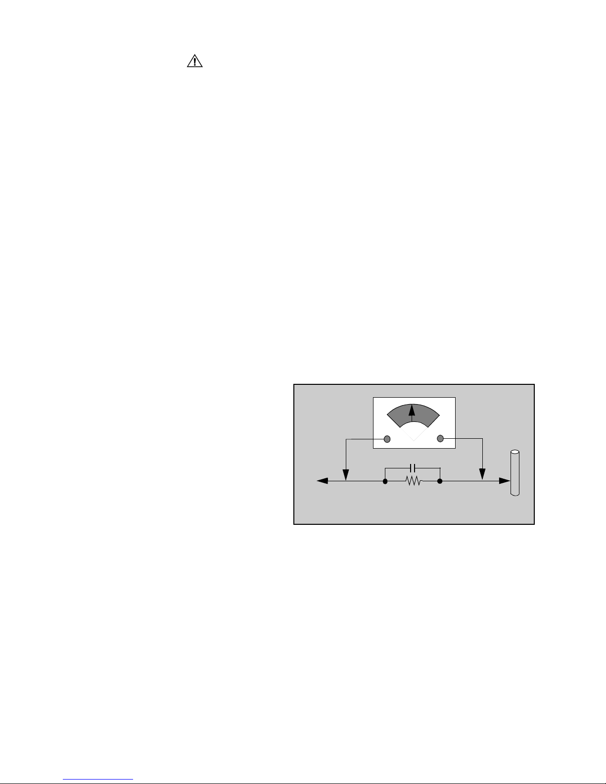
Leakage Current Hot Check (Fig. 1)
Plug the AC cord directly into the AC outlet. Do not use
an isolation transformer during the check.
Connect a 1.5kΩ 10 watt resistor in parallel with a
0.15µF capacitor between an exposed metallic part
and ground. Use earth ground, for example a
water pipe.
Using a DVM with a 1000 ohms/volt sensitivity or
higher, measure the AC potential across the resistor.
Repeat the procedure and measure the voltage
present with all other exposed metallic parts.
Verify that any potential does not exceed 0.75 volt
RMS. A leakage curr ent test er (suc h a S impson M odel
229, Sencore Model P R57 or equival ent) may be used
in the above procedure, in which case any current
measure must not exceed 1/2 milliamp. If any
measurement is out of the specified limits, there is a
possibility of a s hoc k haz ard and the Receiver m ust b e
repaired and rechecked before it is returned to the
customer.
AC VOLTMETER
COLD
WATER
PIPE
(GROUND)
0.15µF
TO INSTRUMENT’S
EXPOSED METAL
PARTS
1500Ω,10 W
Figure 1. Hot Check Circuit
X-ray Radiation
WARNING: The potential source of X-ray radiation in the
TV set is in th e High Vol t a ge section an d th e p ict ure tu be.
Note: It is important to use an accurate,
calibrated high voltage meter.
Set the brightness, picture, sharpness and color
controls to Minimum.
Measure the High Voltage. The high voltage s hould be
31.0kV ± 1.0kV. If the upper limit is out of tolerance,
immediate servic e and correction is requ ired to insure
safe operation and to prevent the possibility of
premature component failu re.
Horizontal Oscillator Disa ble Circuit Test
This test must be performed as a final check before the
Receiver is returned to the customer. See Horizontal
Oscillator Disable Circuit Procedure Check in
this manual.
- 2 -
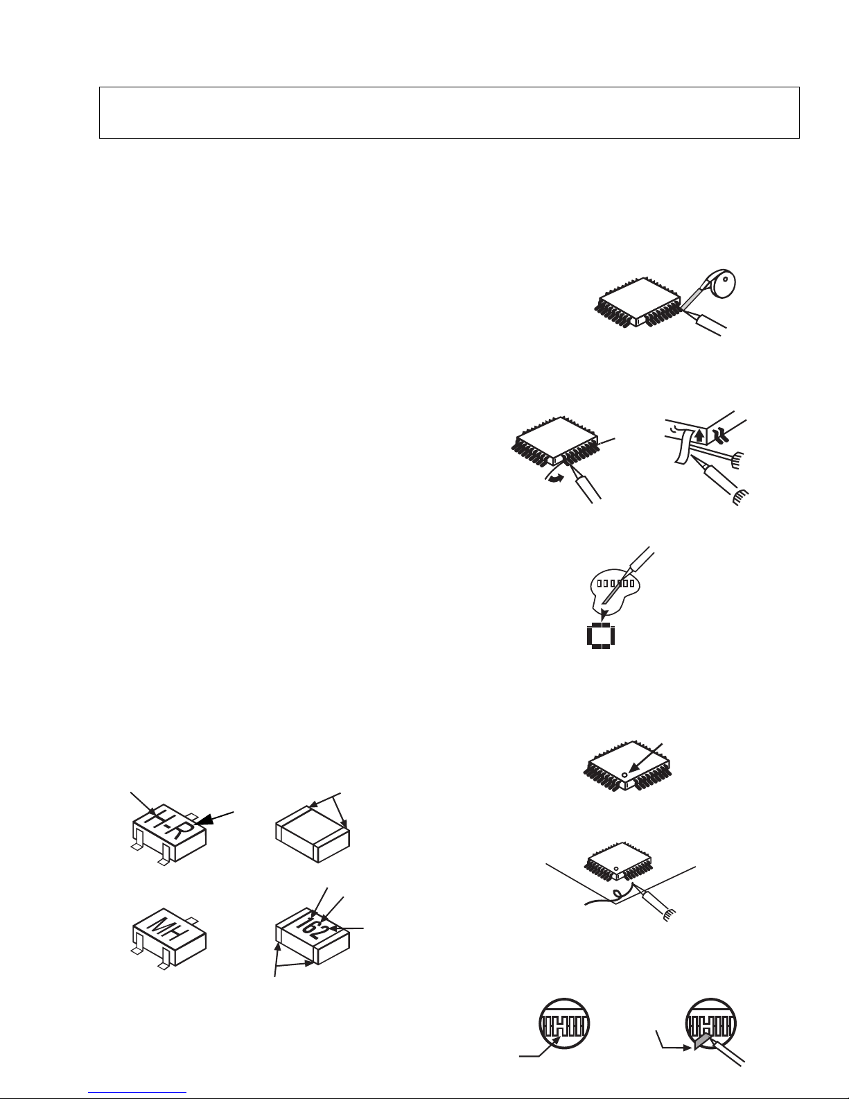
Service Notes
Note: These components are affixed with glue. Be careful not to break or damage any foil under
the component or at the pins of the ICs when removing. Usually applying heat to the
component for a short time while twisting with tweezers will break the component loose.
Leadless Chip Component
(surface mount)
Chip components must be replaced with identical chips
due to critical foil tr ack spacing. There are n o holes in
the board to mount standard transistors or diodes.
Some chips capacitor or resistor board solder pads
may have holes t hrough the board, however the hol e
diameter limits standard resistor replacement to 1/8
watt. Standard capacitor may also be limited for the
same reason. It is recommended that identical
components be used.
Chip resistor have a three digit numerical resistance
code - 1st and 2nd significant digits and a multiplier.
Example: 162 = 1 60 0 o r 1 .6 kΩ resistor, 0 = 0Ω (jumper).
Chip capacitors generally do not have the value
indicated on the capacitor. The color of th e componen t
indicates the general range of the capaci tance.
Chip transistors are identified by a two let ter code . T h e
first letter indicates the type and the second lette r, the
grade of transistor.
Chip diodes have a two lette r i den tif icati on c ode as per
the code chart an d are a dual diode pack with either
common anode or common cathode. Check the parts
list for correct diode number.
Component Removal
1. Use solder wick to remove s older from compo nent
end caps or terminal.
2. Without pulling up, carefully twist the component
with tweezers to break the adhesive.
3. Do not reuse removed leadless or chip
components since they are subject to stress
fracture during removal.
Chip Component Installation
1. Put a small amount of solder on the board
soldering pads.
2. Hold the chip component against the soldering
pads with tweezers or with a miniature alligator clip
and apply heat to the pad area with a 30 watt iron
until solder flows. Do not appl y heat for more than
3 seconds.
TYPE
b
e
ANODES
MH DIODE
Chip Components
GRADE
c
TRANSISTOR
COMMON
CATHODE
SOLDER
CAPS
1ST DIGIT
CAPACITOR
RESISTOR
SOLDER
CAPS
2ND DIGIT
MULTIPLIER
=1600 = 1.6k
How to Replace Flat-IC
- Required Tools -
• Soldering iron • De-solder braids
• Iron wire or small awl • Magnifier
1. Remove the solder from all of the pins of a Fla t-IC
by using a de-solder braid.
Flat-IC
2. Put the iron wire under the pins of the Flat-IC and
pull it in the direction indicated while heating the
pins using a soldering iron. A small awl can be
used instead of the iron wire.
Iron
Wire
Soldering
Pull
Iron
3. Remove the solder from all the pads of the Fla t-IC
by using a de-solder braid.
Flat IC
4. Position the new Flat-I C in place (app ly the pins of
the Flat-IC to the soldering pads where the pins
need to be soldered). Properly determine the
positions of the soldering pads and pins by
correctly aligning the polarity symbol.
5. Solder all pins to the soldering pads using a fine
tipped soldering iron.
Solder
6. Check with a magnifier for solder bridge between
the pins or for dry join t between pi ns and sold erin g
pads. To remove a solder bridge, use a de-s older
braid as shown in the figure below.
Solder
Bridge
- 3 -
Soldering
Iron
Soldering
Iron
De-Solder
Braid
123.....
De-Solder
Braid
Polarity Symbol
Soldering
Iron
Soldering
Iron
De-Solder
Braid
Awl
Important Safety Notice . . . . . . . . . . . . . . . . . . . 2
Safety Precautions . . . . . . . . . . . . . . . . 2
General Guidelines . . . . . . . . . . . . . . . . . 2
Leakage Current Cold Check . . . . . . . . . 2
Leakage Current Hot Check . . . . . . . . . . 2
X-ray Radiation . . . . . . . . . . . . . . . . . . . . 2
Horizontal Oscillator Disable
Circuit Test . . . . . . . . . . . . . . . . . . . . 2
Service Notes . . . . . . . . . . . . . . . . . . . . . . . . . . . 3
Leadless Chip Component
(surface mount) . . . . . . . . . . . . . . . . . . . . 3
Component Removal. . . . . . . . . . . . . . . . 3
Chip Component Installation . . . . . . . . . . 3
How to Replace Flat-IC . . . . . . . . . . . . . . 3
Horizontal Oscillator Disable Circuit . . . . 6
Receiver Feature Table . . . . . . . . . . . . . . . . . . . 7
Board Designation . . . . . . . . . . . . . . . . . . . . . . . 8
Location of Controls (Receiver) . . . . . . . . . . . . 9
Quick Reference Control Operation . . . . 9
Location of Controls (Remote) . . . . . . . . . . . . 10
Initial Center Static Convergence . . . . . 15
Purity Adjustment . . . . . . . . . . . . . . . . . 15
Final Convergence Procedure. . . . . . . . 15
Dynamic Corvergence Adjustment . . . . 15
DY(YHC, YV, XV) Adjustment . . . . . . . . 15
YV Adjustment (VR1 for
Horizontal dynamic convergence) . 15
YH Adjustment (VR2 for Vertical
dynamic convergence) . . . . . . . . . . 15
XV Adjustment(precise adjustment) . . 156
Permalloy Convergence Corrector
Strip (Part No. 0FMK014ZZ) . . . . . . 17
DAF Adjustment . . . . . . . . . . . . . . . . . . 17
Serviceman Mode (Electronic Controls) . . . . 19
Quick Entry to Serviceman Mode . . . . . 19
To toggle between Aging and
Serviceman modes . . . . . . . . . . . . . 19
Exiting the Serviceman Mode . . . . . . . . 19
To Check Purity . . . . . . . . . . . . . . . . . . . 19
Entering Servicem an Mode
(Back-Open Method). . . . . . . . . . . . 19
Service Adjustment Values . . . . . . . . . . . . . . . 20
Instructional Flow Chart for
Serviceman Mode . . . . . . . . . . . . . . 22
Service Adjustments
(Electronic Controls) . . . . . . . . . . . . . . . . . 24
Disassembly for Service . . . . . . . . . . . . . . . . . 11
Back Cover . . . . . . . . . . . . . . . . . . . . . . 11
A-Board . . . . . . . . . . . . . . . . . . . . . . . . . 11
L-Board . . . . . . . . . . . . . . . . . . . . . . . . . 11
H-Board . . . . . . . . . . . . . . . . . . . . . . . . . 11
AG-Board. . . . . . . . . . . . . . . . . . . . . . . . 11
DG-Board . . . . . . . . . . . . . . . . . . . . . . . 11
Q-Board. . . . . . . . . . . . . . . . . . . . . . . . . 11
P-Board . . . . . . . . . . . . . . . . . . . . . . . . . 11
G-Board. . . . . . . . . . . . . . . . . . . . . . . . . 11
Speakers . . . . . . . . . . . . . . . . . . . . . . . . 12
Disassembly for CRT Replacement . . . . . . . . 12
CRT Replacement. . . . . . . . . . . . . . . . . 12
Back Cover Removal . . . . . . . . . . . . . . . . . . . . 13
Chassis Service Adjustment Procedures . . . 14
140.0V B2+ Voltage Check . . . . . . . . . . 14
Source Voltage Chart . . . . . . . . . . . . . . 14
High Voltage Check. . . . . . . . . . . . . . . . 14
Purity and Convergence Procedure . . . . . . . . 15
When the CRT or the Yoke
is Replaced . . . . . . . . . . . . . . . . . . . 15
Vertical Raster Shift Adjustment . . . . . . 15
Sub-Brightness . . . . . . . . . . . . . . . . . . . 24
Sub-Contrast . . . . . . . . . . . . . . . . . . . . . 24
Color Output Adjustment . . . . . . . . . . . . 24
Color Temperature Adjustment
(B/W Tracking) . . . . . . . . . . . . . . . . 25
Complete Adjustment . . . . . . . . . . . . . . 25
Deflection Adjustments . . . . . . . . . . . . . 26
H Center Adjustment . . . . . . . . . . . . . . . 26
Vertical Linearity(V-C), V-Size
and V-Position Adjustment . . . . . . . 26
V-S, V-Size Adjustment . . . . . . . . . . . . . 26
Trapezoid Adjustment . . . . . . . . . . . . . . 26
Parallelogram Adjustment . . . . . . . . . . . 27
E-W PCC Balance Adjustment . . . . . . . 27
E-W PCC Adjustment . . . . . . . . . . . . . . 27
Corner PCC Adjustment . . . . . . . . . . . . 27
H-Size Adjustment. . . . . . . . . . . . . . . . . 27
MTS Circuit Adjustments . . . . . . . . . . . . 28
Input Level Adjustment . . . . . . . . . . . . . 28
Stereo Separation Adjustment
(SEPAH) . . . . . . . . . . . . . . . . . . . . . 28
Sub Picture YUV output adjustment . . . 29
Clock Adjustment (CLOCK). . . . . . . . . . 29
Service Adjustments
(Mechanical Controls) . . . . . . . . . . . . . . . . 30
Width Correction Adjustment. . . . . . . . . 30
Focus (part of T551) . . . . . . . . . . . . . . . 30
- 4 -

Audio Signal Path Block Diagram. . . . . 31
Video-Chroma Signal Path
Block Diagram . . . . . . . . . . . . . . . . 32
IIC Connection . . . . . . . . . . . . . . . . . . . 33
IC001 IN/OUT Pins and
Functions (MPU) . . . . . . . . . . . . . . 34
Identification of Components. . . . . . . . . . . . . 35
Parts List . . . . . . . . . . . . . . . . . . . . . . . . . . . . . 39
Foldouts Notes. . . . . . . . . . . . . . . . . . . . . . . . . 54
Connection Diagram . . . . . . . . . . . . . . . . . . . . 55
Connectors Description . . . . . . . . . . . . . . . . . 56
Schematics, Voltages & Waveforms
L-Board Schematic,
Layout & Voltages . . . . . . . . . . . . . 57
A-Board Schematic (Left Portion). . . . . 58
A-Board Schematic (Right Portion)
& Voltages . . . . . . . . . . . . . . . . . . . 59
A-Board Layout. . . . . . . . . . . . . . . . . . . 60
G-Board Schematic,
Layout & Voltages . . . . . . . . . . . . . 61
D-Board Schematic (Left Portion). . . . . 62
D-Board Schematic (Right Portion)
& Voltages . . . . . . . . . . . . . . . . . . . 63
D-Board Layout. . . . . . . . . . . . . . . . . . . 64
P-Board Schematic & Voltages. . . . . . . 65
Q-Board Schematic & Voltages . . . . . . 66
P & Q-Board Layouts . . . . . . . . . . . . . . 67
AG-Board Schematic & Voltages . . . . . 68
H-Board Schematic & Voltages . . . . . . 69
AG-Board Layout . . . . . . . . . . . . . . . . . 70
H-Board Layout. . . . . . . . . . . . . . . . . . . 71
Waveforms . . . . . . . . . . . . . . . . . . . . . . 72
Parts List Abbreviations Guide . . . . . . . 75
- 5 -
Service Notes (Continued)
IMPORTANT: To protect against possible damage to
the solid state devices due to arcing or static discharge,
make certain that all ground wires and CTR DAG wire
are securely connected.
CAUTION: The power supply circuit is above earth
ground and the chassis cannot be polarized. Use an
isolation transformer when servicing the Receiver to
avoid damage to the test equipmen t or to the chassis.
Connect the test equipment to the proper ground
(Hot ) or (Cold ) when servicing, or incorrect
voltages will be measured.
WARNING: This Receiver has been designe d to meet
or exceed applicable safety and X-ray radiation
protection as specified by government agencies and
independent testing laboratories.
To maintain original product safety design standards
relative to X-ray radiation and shock and fire hazard,
parts indicated with the s ymbol on the schematic
must be replaced with identi cal parts. Order parts from
the manufacturer’s parts center using the parts
numbers shown in t his service manual, o r provide the
chassis number and the part reference number.
For optimum perfo rmance and r eliabil ity, all other parts
should be replaced with components of
identical specification.
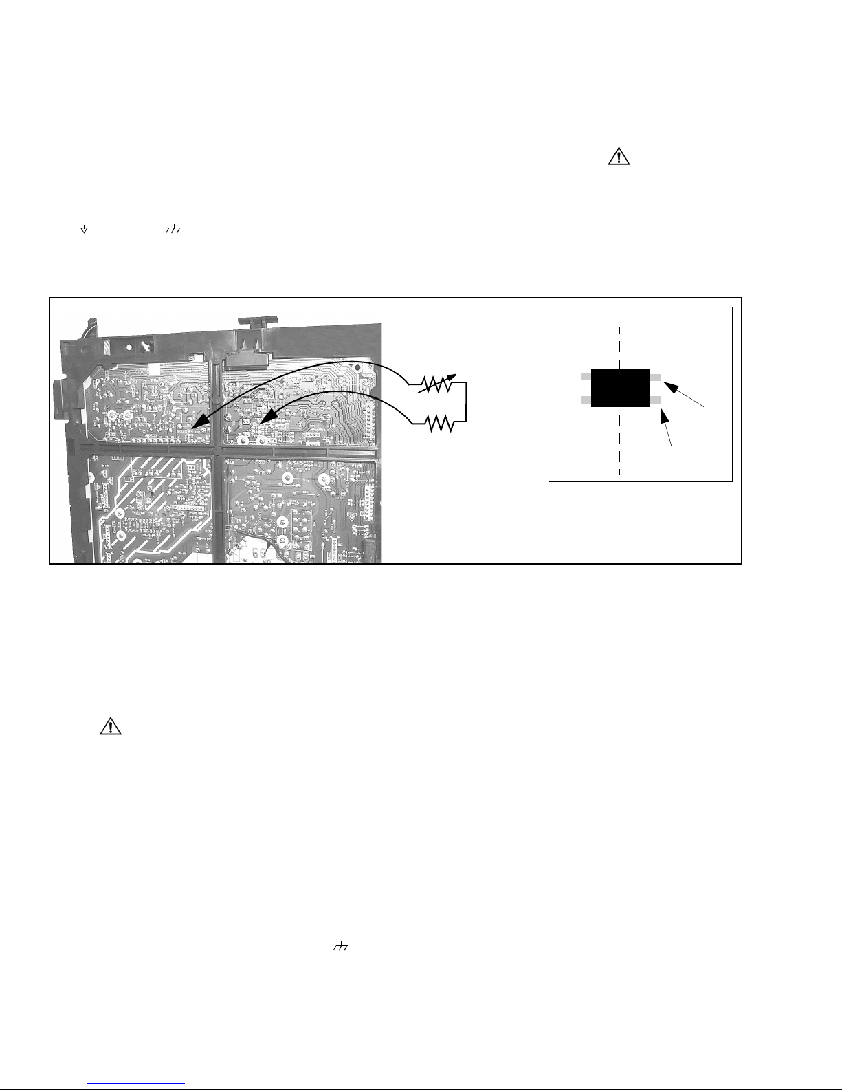
Alternative test points
Horizontal Oscillator Disable Circuit
This chassis employs a special circuit to protect
against excessive high voltage and beam current. If, for
any reason, the high voltage and beam cur rent exceed
a predetermined level this protective circuit activates
and detunes the horizontal oscillator that limits the high
voltage. The over-voltage protection circuit is not
adjustable. However, if components indicated by the
symbol on the schematic in either the horizontal
sweep system or the over-voltage protection circuit
itself are changed, the operation of the circuit should be
checked using the following procedure:
Equipment needed to check the disabled circuit:
1. High Voltage Meter (0- 50kV)
2. Variac or Isolation Transformer
3. 1k ohm VR
4. DC Ammeter
Preparation
1. Connect Receiver to AC 120 Volts. Do not turn ON.
2. Connect HIGH VOLTAGE meter to 2nd anode
(H.V. button).
negative lead.
3. Connect the ammeter serial from the flyback anode
lead to the picture tube anode socket.
4. Prepare HHS jig to be connected betwee n TPD50
and TPD51 as shown above.
Note: Use cold ground( ) for
TPD50
1kΩ
HOT
GROUND
COLD
GROUND
HHS Jig
TPD51
100Ω
IC811
(OPTO)
(Led Anode)
TPD51
(Led Cathode)
Figure 2. Power Supply Jig Detail
(D-Board)
Procedure
:
1. Open Connector A17.
2. Turn power ON and Apply a monoscope pattern.
3. Set current within 50-100µΑ
by changing the
picture and bright controls.
4. Turn power OFF.
5. Connect HHS jig between TPD50 and TPD51 as
shown above (VR should be turn fully clockwise).
6. Turn power on.
7. Using the variable resistor slowly increase the
current until th e hori zontal sy nc freq uen cy abr uptly
increases indicating that the horizontal frequency is
just beginning to pull out of sync. Maintain the
current within
50-100µΑ by chan ging the picture
and bright controls
8. Observe the High Voltage meter. HIGH VOLTAGE
should read less than 40.2kV.
9. Turn power OFF, Remove HHS jig, HV meter,
ammeter and connect A17 connector.
10. Turn Power ON. Reset Picture and Brightness
controls. Confirm B+ 144V±1.5V with 120V AC
applied.
Note: IF HIGH VOLTAGE IS NOT WITHIN
THE SPECIFIED LIMIT THE CAUSE
MUST BE DETERMINED BEFORE
THE RECEIVER IS RETURNED TO
THE OWNER.
TPD50
- 6 -
Receiver Feature Table
FEATURE\MODEL CT-32HX40B/CB CT-36HX40B/CB
Chassis DX2P
Tuning system 256K
# of channels 181
Menu language ENG/ESP/FR
Closed Caption X
V-Chip (USA/CANADA) X
Picture in Picture PIP 2T
2RF X
Remote Model # EUR511158
Picture tube M80LSW195X A90LSW195X
Flat/Superflat F (4:3)
Comb 3D Y/C
H. Edge Correction W/VEC
NEW Y NR X
VM X
Color Temp X
V/A norm (X=both) X
MTS/SAP/DBX X
Built-in audio power 15W/CH(10%)
# of speakers 2
Bass/Bl/Tre Control X
AI Sound X
Spatializer X
A/V in (rear/front) 4(3/1)
A/V Prog Out X
Component Input 2
Audio Out (FAO,VAO) F,V
S-VHS Input (rear/front) 2/1
Dolby Center Ch In X
EPJ/HPJ/MISC HPJ
Dimensions mm
(HxWxD) in
Weight (kg/lbs) 74.8/164.56 98.5/216.7
667.3x810x568
26.52x32.4x22.72
747x936x610.5
29.88x37.44x24.42
Power source (V/Hz) 120/60
Anode voltage 31.0kV (+1.0kV, -2.0kV)
Video input jack
Audio in put jack 500mV RMS 47kΩ
75Ω phono jack
1 V
p-p
Table 1. Receiver Features
- 7 -
Board Designation
Board 32” & 36” Models Description
A-Board TNPH0337 Main Chassis
L-Board TNPA1667 CRT Drive
P-Board TNP A166 6 Power Supply
H-Board TNPA1664 A/V Switch
G-Board TNPA1670
D-Board TNPH0338
Q-Board TNPA1665 Geometry, V-Drive
AG-Board TNPA1668 Chroma
DG-Board TNPA1669
Specifications are subject to change without notice or obligation.
Dimensions and weights are approximate.
Keyboard, Video-4 Input, Speaker
connector , Ge oma gnet ic
Deflection, Sweep, Power Supply,
H-Drive
Non-Serviceable
Comb Filter, Digital Processing,
PIP Processing
- 8 -
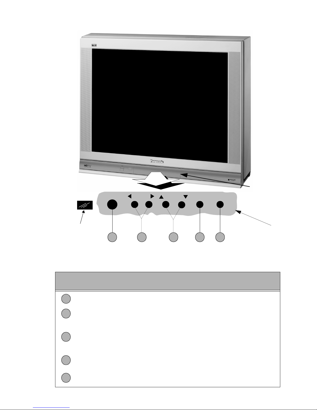
Location of Controls (Receiver)
Remote Control
Sensor
1
Power Button - Press to turn ON or OFF.
Volu me Button s - Press to adjust Sound Level, or to adjust Audio Menus, Video
2
Menus, and select operating features when menus are displayed
Channel Buttons - Press to select programmed chan nels. Press to highlight des ired
features when menus are dis played. Also use to s elect Cable Conver ter box c hannel s
3
after programming Remo te Control Infrared codes (the TV/AUX/C ABLE switch must
be set in CABLE position).
POWER
1 2 4 53
VOLUME
CHANNEL ACTION TV/VIDEO
Figure 3. Location of Controls Receiver
Quick Reference Control Operation
Quick Reference
Control Operation
Front A/V Jacks
Controls Inside
front doo r
Action Button - Press to display Main Menu and access On Screen feature and
4
Adjustment Menus.
TV/Video Button - Press to select TV or one of two Video Inputs, for the Main Pictur e
5
or the PIP frame (when PIP frame is displayed).
- 9 -

Location of Controls (Remote )
POWER Button
Press to turn ON and OFF.
MUTE Button
Press to mute sound.
A second press resumes sound.
Press also to access and delete
Closed Caption display.
VCR, DVD, LD/CD, AUX, TV, CBL,
DBS, RCVR
Component function buttons
VOL (volume) Buttons
Press to adjus t TV sound level.
Use with Channel buttons to
navigate in menus.
R-TUNE (Rapid Tune) Button.
Press to switch to the previous
channel.
ACTION Button
Press to display Main Menu and
access or exit On Screen features
and Adjustment Menus.
REW, PLAY, FF, TV/VCR, STOP,
PAUSE, REC, VCR CHANNEL
LIGHT
Press to light Remote control buttons
MULTI Button
Programmable button that can
operate up to seven (7) functions at
once
TV/VIDEO Button
Press to select TV or Video input.
CH (channel) Buttons
Press to select channels.
Use with volume buttons to
navigate in menus.
DBS EXIT, DBS GUIDE
DBS function buttons.
RECALL Button
Press to display Time, status
of Sleep Timer, Channel,
Video mode and Channel
Caption (Station Identifier).
OPEN/CLOSE, SLOW, STILL
DVD function buttons.
“0” - “9”
Component function buttons.
Figure 4. Location of Controls (Remote)
For more functions and information about this
Remote Control, refer to the Remote Guide listed
in Parts List of this manual
Press numeric keypad to select any
channel.
EUR511158
- 10 -
Disassembly for Service
Back Cover
Remove all the screws marked with an arrow( )
from the back of the Receiver. (See Fig. 8)
Note: Screw configuration, type, and number
of screws vary depending on the
model of the Receiver serviced and
the application; various models are
covered in this Manual. Use same
hardware when reassembling the
receiver.
• 4 screws at the top edge of the Receiver.
• 4 screw by the A/V jacks.
• 1 screw by the antenna jacks.
• 1 screw by the
• 1 screw at the lower part of TV.
• 1 screw at each lower corner of the Receiver.
• 1 screw by the retainer plate of the AC power cord.
• 1 screw by the AC Cord assembly.
Note: Extensions for board connectors may
A-Board - Main Chassis (See Fig. 49)
The H, AG and DG-Board ar e assembled on the M ain
chassis (A-Board). When servicing these boards,
extension cables may b e required. Cables kit can be
ordered from Matsushita Services Company, Part
No. TXAZS011SER. The A-Board assembly rest on a
chassis tray along with the D-Board.
Slide chassis tray out. Gently lift, tray and pull out.
Disconnect plug connectors; release wire ties and
holders as required for complete chassis removal.
A. A-Board is secured to the chassis tray with five
screws.
B. The D-Board is secured to the chassis tray with
five screws
C. The A-Board is mated to the D-Board by four
flexible connectors: A4, A5, A6 & A7 (D4, D5, D6 &
D7 on the D-Board, respectively). T o remove either
boards, unplug the connectors on the A-Board.
Note: Some tie-wraps that secure the wire
Dolby Center Ch Input.
be needed to take voltages on
H-Board, AG-Board, Q-Board and
P-Board, please see Parts List section
for part numbers in this Service
Manual.
dressings may need to be unfast ened
for chassis removal.
Insert wire then
pull upwards
Note: To realease the
GND cable from
A20 connector
insert a wire in
both cavities of
connector, then
pull the cable.
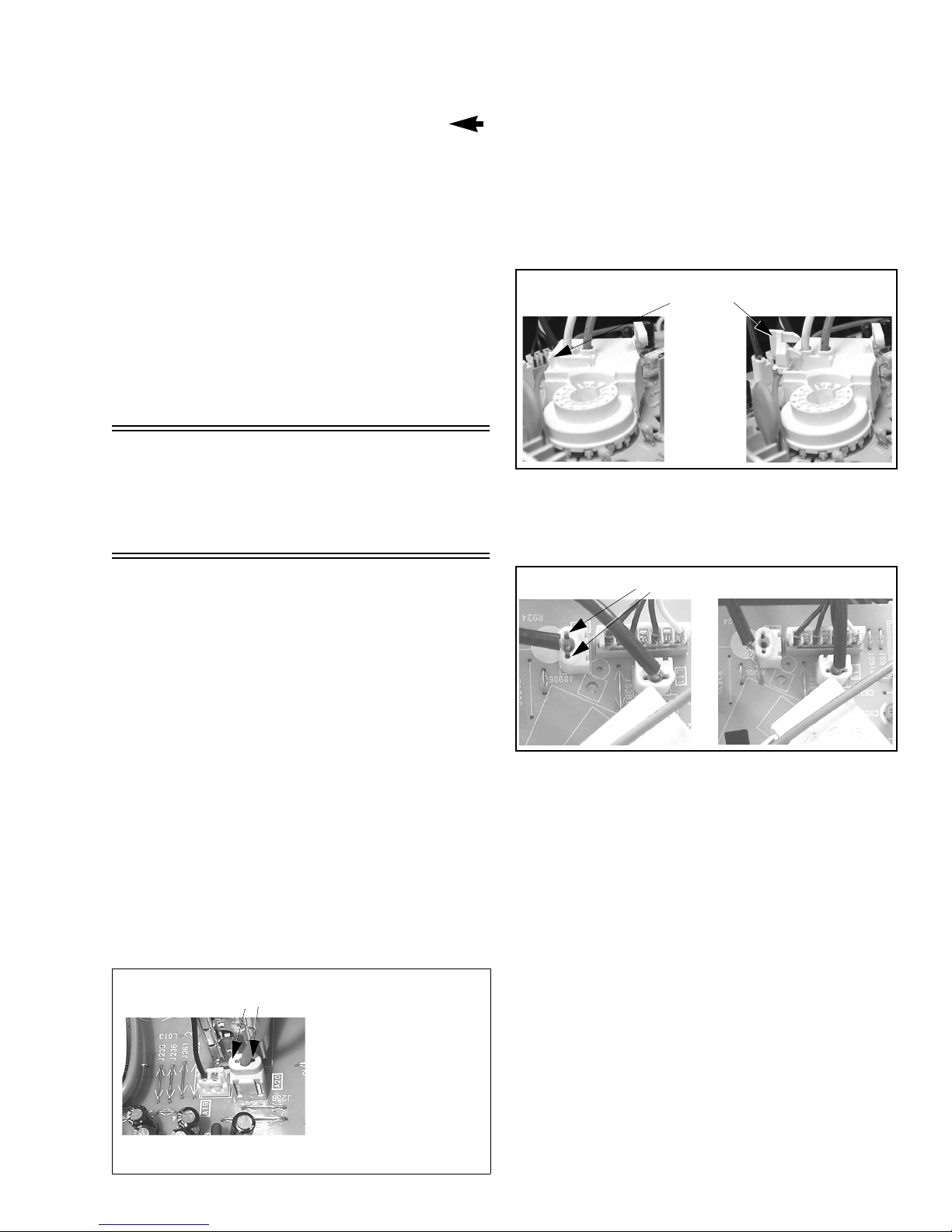
L-Board - CRT Output
Plugs into the socket on the CRT neck.
To remove thi s board, first unplug the board from
the CRT neck, then disconnect L1, L2 & L3
connectors, to disconnect the foc us F1(Red Cabl e)
& F2(White Cable) ca ble s, pull th e tab and rele ase
the cables, finally disconnect the screen cable from
the D-Board D16.(See Fig. 6).
To reinser t back the cabl es, remember the original
position of cables, F1(re d cable) goes to A on the
CRT socket and F2(white cable) go es to B on the
CRT socket.
Press tab
leftward to
release cables
Figure 5. F1 & F2 cables release
T o r elease screen GND cables from L-Board L11 & L12
connectors, insert a wire in both sides of connector and
pull upwards the cable, then re move the wire
(See Fig. 6)
Insert wire
Figure 6. L-Board Screen GND cables release
Pull cable upwards
Pull cables
upwards
H-Board - A/V Jacks, S-Video Connectors,
and S-Video Switch
Plugs onto A-Board at the A9 connector.
Note: Use a small flat head screwdriver to
release the connector locking tabs.
AG-Board
Plugs onto A-Board at the A25 & A26 connectors.
Note: Use a small flat head screwdriver to
release the connector locking tabs.
DG-Board
Plugs onto the A-Board at the A10 connector.
Note: This Board is Not-Serviceable.
When removing this board pull carefully.
Q-Board
Plugs onto the D-Board at the D8, D9 & D10
connectors.
P-Board
Plugs onto the rig ht side of the D- Board at D1, D 2
& D3 connectors; First remove the three screws
that holds the metal board, one from the flyback
- 11 -
and two from the chassis tray and then use a flat
head screwdriver to release the connector locking
tabs and pull upwards the board.
G-Board
Mated to A-Board by three flexi ble connecto rs. To
remove this board, first unplug the three flexible
connectors, then pull upwards the board while
unlock the tabs from the chassis tray.
Degauss
Coil
Bracket
Degauss
Coil
Speakers
Each speaker is secured to a plastic base with
4 screws, and each plastic base is secured to a
second base with two screws, a nd secured to the
cabinet with two screws.
Note: Be sure to reconnect the speaker
wires to the correct speaker lead (+) (-)
Disassembly for CRT
Replacement
1. Discharge the CRT as instructed in the Safety
Precautions (see page 2) and remove 2nd anode
button from the CRT.
2. Remove Speaker Modules (R & L)
3. Perform complete removal of Chassis, as
instructed in Disassembly for Service.
Note: When remounting the CRT, reus e th e
metal sheet located in the lower part of
the cabinet holding the CRT, hold with
screws to the cabinet. This metal sheet
is not supplied with the CRT
replacement.
CRT Replacement
1. Perform Disassembly for CRT Replacement
procedure.
2. Insure that the CRT H.V. Anode button is
discharged before handling the CRT. Read the
Safety Pr ecautions ( see page 2) on handling the
picture tube.
3. Remove the components from the CRT neck and
place the cabinet face down on a soft pad.
4. Note the original order for the CRT mounting
hardware as they are remove from the CRT
mounting brackets at each corner of the CRT.
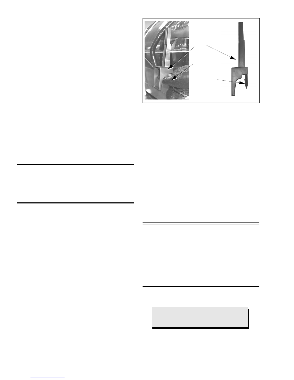
5. Remove the CRT with the dega ussing coil and the
dag ground braid attached.
Note: To remove the four brackets holding
the degauss coil from the corners of
the CRT, first remove the CRT from
the cabinet, then remove the Brackets
by pressing the tab on the bracket and
pull upwards. These Brackets are
included in the Degauss Coil Kit, for
part number, please see parts list
section (See Fig. 7).
Press tab
Then Pull
Upwards
Figure 7. Brackets removal
6. Note the original locations and mounting of the
degaussing coil and the dag ground assembly to
insure proper reinstallation on the replacement
CRT.
To remove and remount the degaussing coil:
The degaussing co il is held in place by clampe rs
fastened to the CRT corner ears. These clampers
must be installed onto th e replacement CRT prior
to mounting the degaussing coil.
To remove and remount the dag ground braid:
a.Unhook the coil sprin g from the bottom corners
of the CRT ears.
b.Release the braid loop from the upper corners of
the CRT ears.
7. Mount the dag ground braid on the replacement
CRT. Position the degaussing coil with new ties.
Dress coil as was on the original CRT.
8. Replace the components on CRT neck and
reinstall into cabinet. Verify that all ground wires
and circuit board plugs get connected.
Note: Reuse all the clampe rs and mounting
brackets from the degauss coil and
screen, and when remounting the
degauss coil assure that is not
touching the speakers, this can be
done by placing some tape
(See Fig. 7), this may cause mask
vibration. The mounting brackets and
clampers are not supplied with the
replacements.
Important Notice:
When ordering the CRT, please order CRT
and CRT KIT also. Please see parts list
section for part numbers
- 12 -

Back Cover Removal
4 SCREWS
AT THE TOP EDGE
1 SCREW
AT THE LOWER
CORNER
1 SCREW BY
THE
ANTENNA
JACKS
1 SHORT
SCREW
1 SCREWS
4 SCREWS
Figure 8. Back Cover Removal.
- 13 -
1 SCREW
AT THE LOWER
CORNER
1 SCREW
BY THE RET AINER PLA TE
OF THE AC CORD
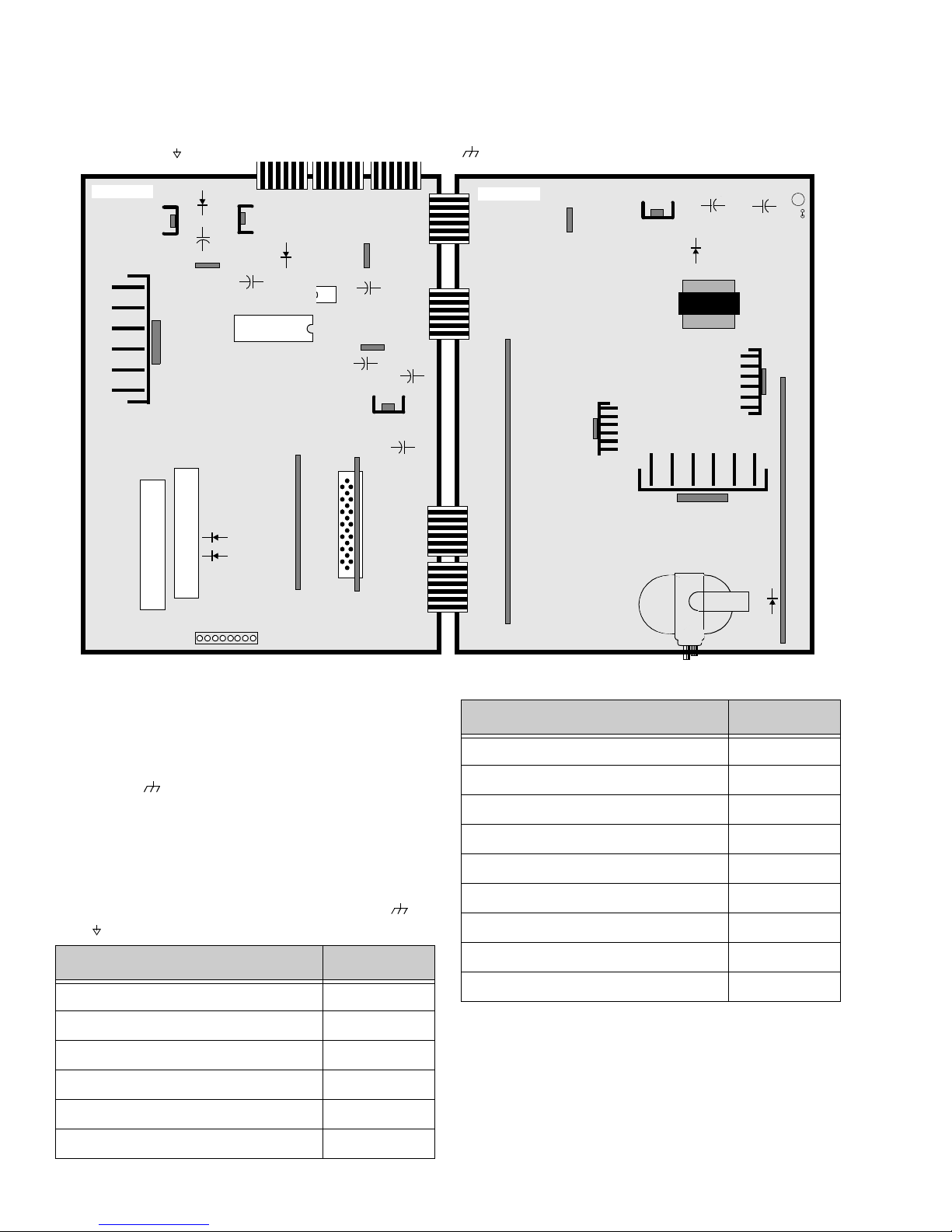
Chassis Service Adjustment Procedures
All service adjustments are factory preset and should not require adjustment unless controls and/or
associated components are replaced.
Note: Connect the (-) lead of the voltmeter to the appropriate ground. Use Q801’s heat sink when the HOT
ground symbol ( ) is used. Otherwise, use COLD ground ( ) — Tuner shield, IC2301’s heat sink (See Fig. 50)
A-BOARD
IC2301
D894
IC875
IC871
+
+
IC876
C892
T
T
U
U
N
N
E
E
R
R
D007
D008
TP
D899
-
IC001
AG-BOARD
18
IC002
+
+
C027
DG-BOARD
IC880
C874
IC003
-
+
IC872
+
C879
C878
-
-
D-BOARD
Q-BOARD
IC802
D825
D503
C840
-
D826
T801
Q551
+
Q801
P-BOARD
C838
-
L827
+
L824
D511
MOMENTARILY CONNECT A JUMPER FOR ENTERING SERVICE MODE (FA1 to FA2)
140.0V B2+ Voltage Check
1. Set the Bright and P icture to Minimum by using
the Picture Menu.
STBY 5.0V (IC002 PIN-8) A-Board TPA17 5.0 ± 0.2V
LOCATION VOLTAGE
2. Connect the DVM on TPP17 (D-Board) and cold
ground ( ).
3. Confirm that B2+ voltage is 144.0V ± 1.5V. This
BTL 30V (CATHODE D007)
+B2 (BY IC802 & Q854) D-Board TPP17 144.0V ± 1.5V
A-Board TPA18 32.0V ± 2.0V
voltage supplies B2+ to the Horizontal Output &
Flyback circuits.
Source Voltage Chart
120V AC line input. Se t the Bright and the Picture to
(
Minimum by using the Picture Menu . Use cold
Hot ( ) ground for the (-) lead of the DVM as needed.
LOCATION VOLTAGE
MAIN 12V (IC876 PIN-2)
MAIN 9V (CATHODE D894) A-BoardTPA7 9.0V ± 0.5V
MAIN 5V (IC872 PIN-1)
MAIN 3.3V (IC872 PIN-2)
A-Board TP A6 12.0 ± 0.5V
A-Board TPA8 5.0V ± 0.3V
A-Board TPA14 3.5V ± 0.2
) or
40V (CATHODE D826)
25V (BY D825)
15V (BY C840 & L826) D-Board TPP20 15.0V ± 1.5V
-15V (BY C838 & C838)
SOUND (BY L827 & L824)
220V (CATHODE D511 ) D-Board TPD7 220.0V ± 9.0V
High Voltage Check
1. Select an active TV channel and confirm that
horizont al is in sync.
2. Adjust Brightness and Picture using Picture Icon
D-Board TPP25 40.0V ± 3.0V
D-Board TPP19 26.8V ± 2.0V
D-Board TPP21 -15.1V ± 1.5V
D-BoardTPP22 32.5V ± 2.0V
menu so video just disappears.
GC 3.3V (IC880 PIN-2) A-Board TPA15 3.5V ± 0.2V
STBY 3.3V (IC003 PIN-4)
A-Board TPA16 3.3 ± 0.2V
3. Confirm B2+ 144 ± 1.5V is within limit.
4. Using a high voltage meter confirm that the High
Voltage is 31.0kV ± 1.0kV.
- 14 -
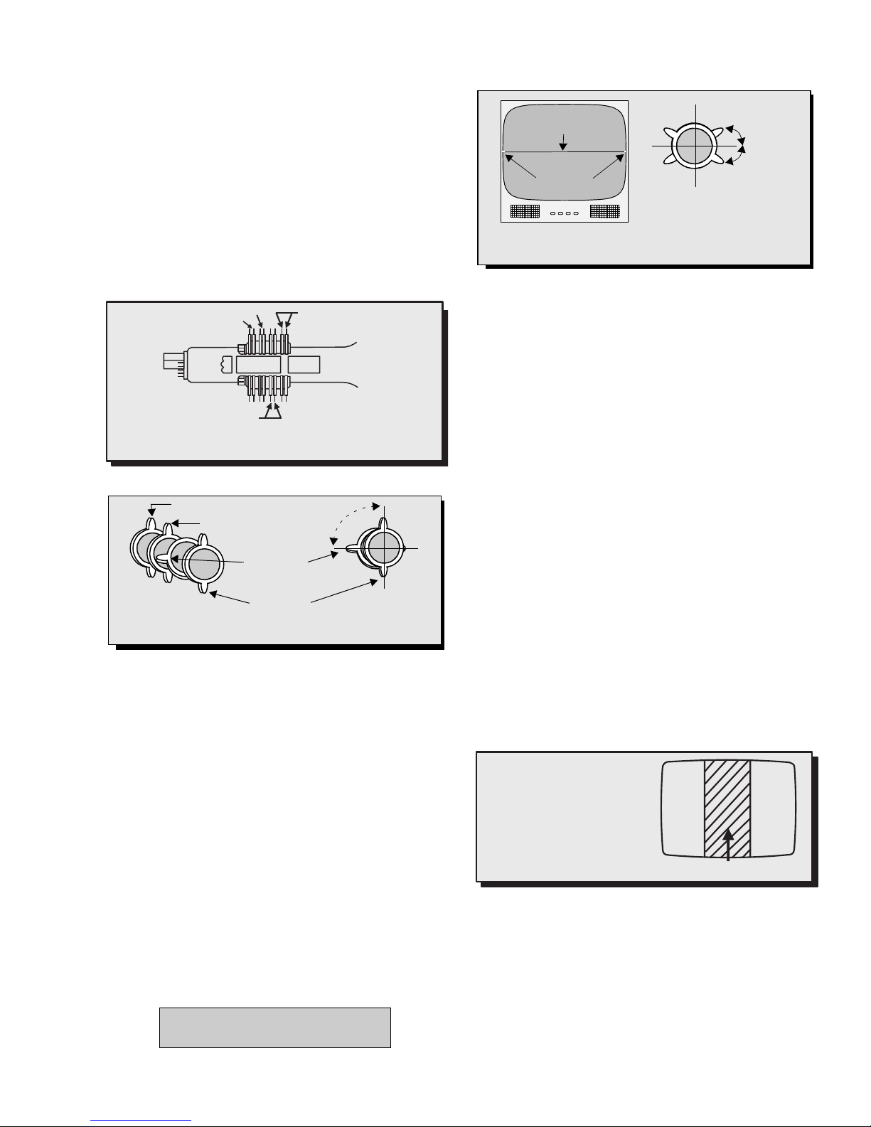
Purity and Convergence Procedure
Adjustment is necessary only if the CRT or the
deflection yoke is replaced or if the setting was
disturbed. The complete procedure consists of:
1. Vertical Raster Shift Adjustment.
2. Initial static convergence.
3. Setting the purity.
4. Final static convergence.
When the CRT or the Yoke is Replaced
Place the yoke on the CRT neck (do not tighten
the clamp).
Place the vertical raster shift tabs at 3 o’clock (90o from
the purity and convergence tabs (See Fig. 9 and
Fig. 10)
R&B Convergence Rings
R&B&G Convergence Rings
G3 G4
Vertical Raster Shift Ring
Figure 9. Description of Rings
R&B&G Convergence Rings
R&B Convergence Rings
Vertical Raster
Shift Rings
Purity Rings
Figure 10. initial positioning of Rings
Turn the Receiver ON. Operate the Receiver for 60
minutes using the first Purity Check field (white screen)
to stabilize the CRT.
Fully degauss the Receiver by using an external
degaussing coil.
Slide the deflection yok e back and forth on the neck of
the CRT until it produces a near white, uniform raster.
Vertical Raster Shift Adjustment
Apply a green pattern with a horizontal line, adjust the
Deflection Yoke so that has no tilt, then secure it.
Adjust center line of the pattern with the mechanical
center of the CRT, this center is determined by two
marks at the side edges of th e screen. To adjust the
line, once the vertical raster shift tabs are place at 3
o’clock to reduc e its magnetic field effect ( see Fig. 9 )
open the tabs the same angle from the cen t er, until the
center line of the pattern becomes a straight line,
centered with the marks of the CRT.
(see Fig. 10)
Important Notice:
Rings come along with Deflection
Yoke in one pie ce .
Purity Rings Centered
Over G3/G4 Gap
o
90
Center line
from pattern
Mechanical
Center Marks
Vertical Raster Shift tabs
Open the
same angle
from center
Figure 11. Vertical Raster Shift Adjustment
Initial Center Static Convergence
Connect a dot/cross hatch generator to the Receiver
and tune in a signal. Observe misconvergence at
center of the screen only.
Adjust the R&B pole magnets; b y separating tabs an d
rotating to converge blue with red.
Adjust the R&B and R&B&G pole magnets: by
separating tabs and rotating to converge blue an d red
(magenta) with green.
Note: Precise convergence at this point is
not important.
Purity Adjustment
When the Receiver is in the Serviceman Mode for
making electronic adjustments, press the Recall button
on the Remote Control to ente r Purity Ch eck. (See the
Service Adjustments Electronic Controls
procedure).
Operate the Receiver for 60 minutes using the first
Purity Check field (white screen) to stabilize the CRT.
Fully degauss the Receiver by using an external
degaussing coil.
Press the Recall button on the Remote Control again
until the Purity Check (green screen) appears.
Loosen the deflection yoke clamp screw an d move the
deflection yoke back as close to the purity magnet
as possible.
Adjust the Puri ty rings to set the vertical gree n raster
precisely at the center of the screen (see Fig. 12).
NOTES:
1. CRT warm up with white screen
(three guns activated) is needed
to stabilize the shadow mask
expansion.
2. Initial center static convergence
(roughly centers three gun
beams) is required in order to
perform purity adjustment.
Figure 12. Green Raster Adjustment
Slowly move the deflect ion yoke forward until th e best
overall green screen is displayed.
Tighten the deflection yoke clamp screw.
Press the Recall button on the Remote Control again
until the purity che ck b lue an d red s creens appe ar and
observe that good purity is obtained on each respective
field.
Press the Recall button on the Remote Control again
until Purity check (wh ite screen) appear s. Observe th e
screen for uniform white. If purity has not been
achieved, repeat the above procedure.
Green Raster
- 15 -
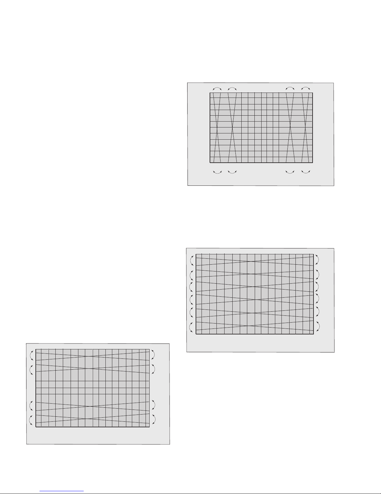
Final Convergence Procedure
G
B&R
G
B&R
G
B&R
G
B&R
Figure 13. VR1 Adjustment (YV)
Note: Vertical size and focus adjustments
must be completed prior to performing the
convergence adjustment. Connect a dot pattern
generator to the Receiver. The Brightness level
should not be higher than necessary to obtain a
clear pattern.
Converge the red and the blue dots at the center of the
screen by rotating the R&B pole Static Convergence
Magnets.
Align the converged red/bl ue dots with the green dots
at the center of t he scr een by r otatin g th e R &B &G p ol e
Static Convergence Magnets. Melt wax with soldering
iron to reseal the magnets.
Slightly tilt vertica lly and hori zontally ( do not ro tate) the
deflection yoke to obtain a good overall convergence.
If convergence is not reached at the edges, insert
permalloy in the DY corners to achieve proper
convergence (See “Permalloy Convergence Correc tor
Strip (Part No. 0FMK014ZZ)” on page 17.) Recheck for
purity and readjust if necessary.
After vertical adjustment of the yoke, insert wedge at 11
o’clock position, then make the horizontal
tilt adjustment.
Secure the deflection yoke by inserting four side
wedges.
Apply adhesive between tab (thin portion) of wedge
and CRT and place tape over the tab to s ecure to the
CRT.
Dynamic Corvergence Adjustment
Use this for a precisely over all convergence adjust at
the edges.
DY(Y
HC, YV, XV) Adjustment
Y
V Adjustment (VR1 for Horizontal dynamic
convergence)
1. Apply a crosshatch pattern.
2. Adjust contrast and brightness customer controls
to obtain a correct picture.
3. With a driver adjust VR1 (located in deflection yoke
board Fig. 19) to obtain a proper corvergence at
top and bottom of the screen (See Fig. 13)
Y
H Adjustment (VR2 for Vertical dynamic
convergence)
1. Apply a crosshatch pattern.
2. Adjust contrast and brightness customer controls
to obtain a correct picture.
3. With a driver Adjust VR2 (located in deflection yoke
board Fig. 19) to obtain a proper corvergence at
left and right side of the screen. (See Fig. 14)
B&R
B&R
B&R
G
G
B&R
G
G
Figure 14. VR2 Adjustment (YH)
XV Adjustment(precise adjustment)
1. Apply a crosshatch pattern.
2. Adjust contrast and brightness customer controls
to obtain a correct picture.
3. With a driver adjust the coil located in deflection
yoke board to obtain a proper convergence
horizontally.
B&R
G
B&R
G
B&R
G
B&R
G
Figure 15. XV Adjustment
Note: Apply a red pattern and confirm purity,
if purity is poor, repeat purity
adjustments.
- 16 -
Permalloy Convergence Corrector Strip
(Part No. 0FMK014ZZ)
This strip is used in some sets to match the yo ke and
CRT for optimum convergence. If th e yoke or CRT is
replaced, the strip may not be required.
First converge the set without the strip and observe
the corners.
If correction is needed:
1. Place strip between CRT and yoke, in quadrant
needing correction. Slowly move it around for
desired results.
2. Press adhesive tightly to the CRT and secure
with tape.
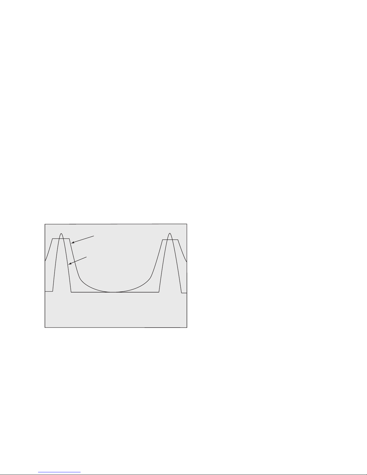
DAF Adjustment
Preparation:
1. Apply a crosshatch pattern.
2. Set user controls, bright to center and picture to
max.
Procedure:
1. Connect channel one of the oscilloscope with
100x1 probe to D1505A (DAF waveform).
2. Connect channel two of th e oscillo scope wi th 10x1
probe to D504K or R519 (FBP waveform).
3. If the peak position of the wav eforms are differen t,
in Serviceman Mode, adjust “HDAFC” DATA so
that become the same position. (See Fig. 16)
DAF
FBP
Figure 16. DAF Adjustment
- 17 -
As the yoke is tilted
RGB
Figure 17. Vertical Yoke Movement
vertically, the rasters
produced by the
outside guns rotate in
opposite directions.
RGB
As the yoke is tilted horizontally, one
raster gets larger while the other gets
smaller
Figure 18. Horizontal Yoke Movement
Raster produced from one of the
outside electron beams
Raster from the other side electron
beam
Static convergence magnets are set for
center convergence
2 Poles(VRS Adj)
4 Poles
6 Poles
Figure 19 . Convergence Magnets and Wedges Location
2 Poles(Purity)
For Adjustment
of DY (YHC/YV/XV)
Dynamic Convergence
IMPORTANT NOTE:
Always Exit the Serviceman
Mode Following Adjustments.
- 18 -
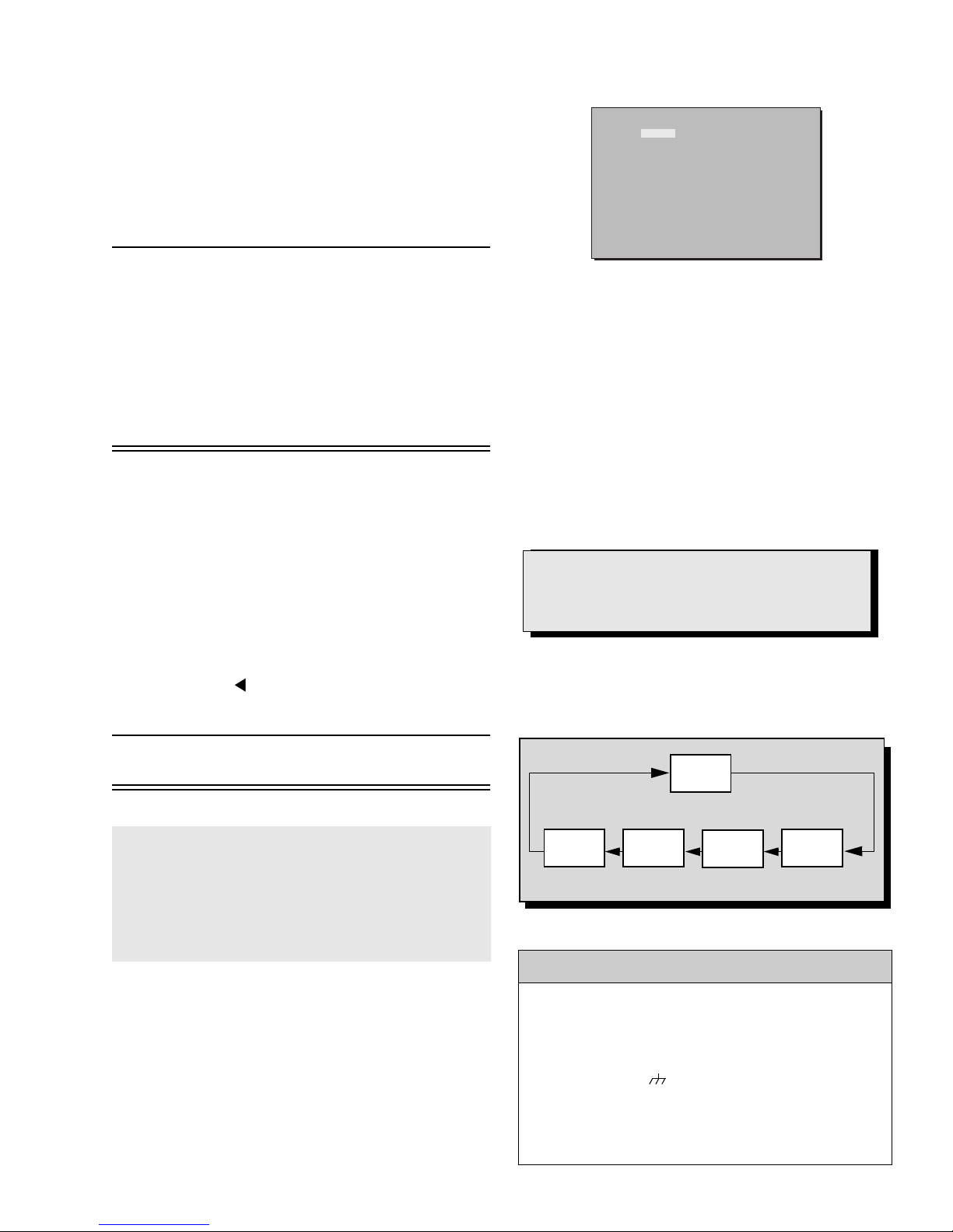
Serviceman Mode (Electronic Controls)
This Receiver has electronic technology using the I²C
Bus Concept. It performs as a control function and it
replaces many mechanical controls. Instead of
adjusting mechanical controls indivi dually, many of the
control functions are now performed by using “On
Screen Display M enu”. (T he Servic eman Adjustment
Mode.)
Note: It is suggested that the technician
reads all the way through and
understand the follow in g p ro cedur e for
Entering/Exiting the Serviceman
Adjustment Mode; then proceed with
the instructions working with the
Receiver. When becoming familiar
with the procedure , the Flow Chart for
Serviceman Mode may be used as a
quick guide.
Quick Entry to Serviceman Mode:
When minor adjustments need to be done to the
electronic controls, the method of Entering the
serviceman Mode w ithout removal of the ca binet back
is as follows using the Remote Control:
1. Select SET-UP icon and select CABLE mode.
2. Select TIMER icon and set SLEEP time for 30 Min.
3. Press “ACTION” twice to exit menus.
4. Tune to the Channel 124.
5. Adjust VOLUME to minimum (0).
6. Press VOL (decrease) on Receiver. Red
“CHK” appears in upper corner.
480I 480P
VDEF
4:3
MTSIN SEPAL
CLOCK
COLOR
B-Y_G
BRT
H LIN
PCCHG
TOPG
TRAP
V RAS
HDAFC
MODE
MTS
CLOCK
VIDEO
SUB Y DRV
HDEF
DAF
16:9
BRIGHT TINT
CUT G
R DR
UVDRV
H POS
1080I
DW
SEPAH
CUT R
B DR
PCCLG PCCHS
BTMG
PARA
VEAMP
VDAFG
H WID
TOPSL
SIDE
V-C V-S
CONT
CUT B
PCC
PCCLS
BTMSL
Figure 20. Serviceman Mode Menu Adjustments.
Note: Some adjustments are available only
in some modes (480 i, 480p, 1080i); it
is needed to apply the format.
Exiting the Serviceman Mode:
Press Action and Power on the Receiver
simultaneously for at least 2 seconds.
THE RECEIVER EXITS SERVICEMAN MODE.
The Receiver momentarily shuts off; then comes back
on tuned to channel 3 with a preset level of sound.
Any programmed c hannel s, ch annels capt ion da ta and
some others user defined settings will be erased.
IMPORTANT NOTE:
Always Exit the Serviceman Mode
Following Adjustments.
To Check Purity:
Press Recall on the Remote Control when in
Serviceman Mode (red “CHK” is displayed) to enter the
Purity Field Check Mode.
Note: After Receiver is set into SERVICEMAN
mode, set TIMER back to NO.
To toggle between Aging and
Serviceman modes:
While the “CHK” is di splayed on the left top corner
of the CRT, pressin g “ACTION” and “VOL” UP on
the TV simultaneously will toggle between the
modes. Red “CHK” for Serviceman and yellow
7. Press Power on the Remote Control to display
the Serviceman Adjustment Modes menu, select
adjustment by pressing the volume right/left
buttons and channel up/down buttons on the
remote and ACTION to enter the adjustment.
NORMAL
SCREEN
Press Recall again to select desired field.
BLUE
SCREEN
GRN.
SCREEN
RED
SCREEN
Figure 21. Purity Check Field Mode.
Helpful Hints
Entering Serviceman Mode (Open-Back
Method)
• While the Receiver is connected and operating in
Normal Mode, momentarily short test point FA1 to
Cold Ground ( ) (A-Board).
The Receiver enters the Aging Mode
Yellow letters “CHK” ap pea r i n t he up per left corner of
the screen.
(The Volume, Up/Down will adjust rapidly).
- 19 -
WHITE
SCREEN
.

For Adjustments:
1.Press Channel Up/Down and
Volume Right/Left on the
Remote Control to select one of
the available Ser vice Adjustments
(Fig. 20). Press ACTION to enter
the adjustment. Press ACTION
again to go back to the
adjustments menu (Fig. 20).
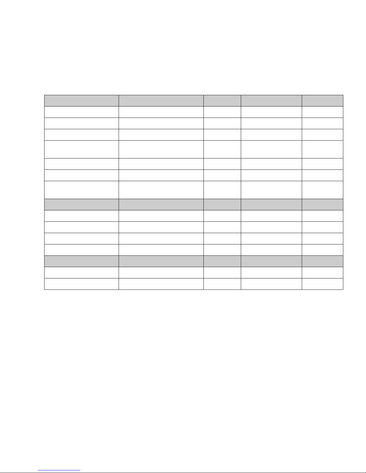
MTS Adjustments Description Mem Loc. Default Level New Level
MTSIN INPUT LEVEL AE 0E 09
SEPAL LOW FREC SEPARATION AE 0F 1F
SEPAH HI FREC SEPARATION AE 10 1F
CLOCK Adjustments Description Mem Loc. Default Level New Level
CLOCK SYNTHESIZER ADJUST. AE 12 128
VIDEO Adjustments Description Mem Loc. Default Level New Level
COLOR COLOR AA 8F 24
Note: Write Down the original
value set f or e ach a ddres s
before modifying anything.
It is easy to erroneously
adjust the wrong item.
2.Press Volume Right/Left on the
Remote Control to adjust the
level of the selected Service
Adjustment (Fig. 20).
TINT TINT AA 91 1F
BRIGHT SUB-BRIGHTNESS AA 93 60
CONT SUB-CONTRAST AA 95 22
B-Y_G COLOR ADJUST. (BLUE) AA AE 2F
CUT G GREEN CUT-OFF AA CC 02 D2
CUT R RED CUT-OFF AA C8 02 92
CUT B BLUE CUT-OFF AA D0 02 56
DOES NOT
BRT TEMPORARY BRIGHTNESS
R DR RED DRIVE AA 96 B1
B DR BLUE DRIVE AA 98 AD
H DEF Adjustments Description Mem Loc. Default Level New Level
H LIN HORIZONTAL LINEARITY AA 76 5F
H POS HORIZONTAL CENTERING A6 EA 37
H WID HORIZONTAL WIDTH A8 32 4F
PCC PINCUSHION CORRECTION A8 30 48
WRITE TO
EEPROM
60
PCCHG PINCUSHION TOP GAIN A8 56 02
PCCLG PINCUSHION BOTTOM GAIN A8 60 01
PCCHS
PCCLS
PINCUSHION TOP SLICE
PINCUSHION BOTTOM SLICE
LEVEL
LEVEL
A8 B6 00
A8 B1 01
- 20 -
For Adjustments:
1.Press Channel Up/Down and
Volume Right/Left on the
Remote Control to select one of
the available Ser vice Adjustments
(Fig. 20). Press ACTION to enter
the adjustment. Press ACTION
again to go back to the
adjustments menu (Fig. 20).
H DEF Adjustment Description Mem Loc. Default Level New Level
TOPG TOP CORNER GAIN A8 A2 13
BTMG BOTTOM CORNER GAIN A8 AC 11
TOPSL TOP CORNER SLICE LEVEL A8 46 01
Note: Write Down the original
value set (
Fig. 20
) for each
address before modifying
anything. It is easy to
erroneously adjust the
wrong item.
2.Press Volume Up/Down on the
Remote Control to adjust the
level of the selected Service
Adjustment (Fig. 20).
BTMSL
TRAP TRAPEZOID A8 2B 75
PARA PARALLELOGRAM A8 65 07
SIDE
VDEF Adjustments Description Mem Loc. Default Level New Level
VRAS VERTICAL CENTERING AA 72 27
VEAMP VERTICAL WIDTH A8 14 62
V-C VERTICAL LINEARITY_1 A8 7E 22
V-S VERTICAL LINEARITY_2 A8 74 1E
DAF Adjustments Description Mem Loc. Default Level New Level
HDAFC HORIZONTAL DAF A8 05 17
VDAFG VERTICAL DAF A8 C5 AA
BOTTOM CORNER SLICE
LEVEL
PINCUSHION BALANCE
ADJUST.
A8 3C 0B
A8 6A 00
- 21 -
WHITE
SCREEN
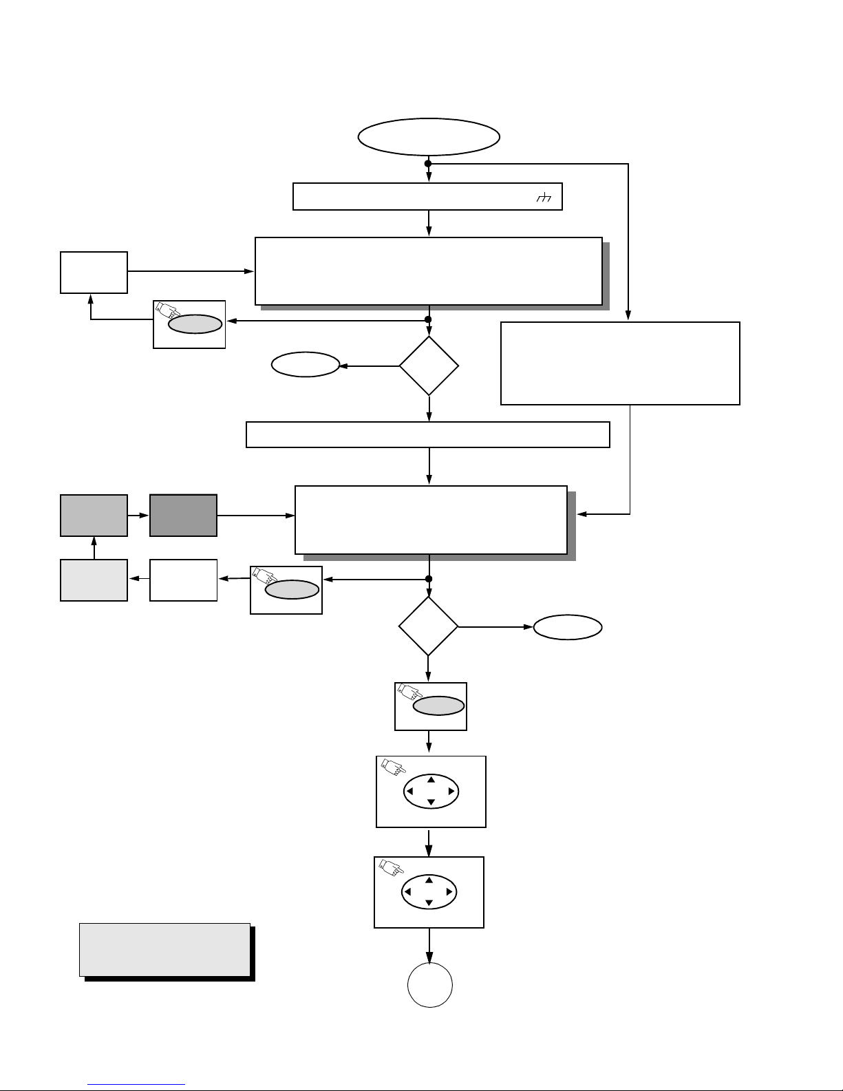
Instructional Flow Chart for Serviceman Mode
NORMAL MODE
Momentarily short FA1 to COLD GND ( ).
AGING MODE
• Yellow “CHK” appears in upper left corner of screen.
• Volume Up/Down operate rapidly.
• Customer Controls are set to nominal level.
GRN.
SCREEN
RED
SCREEN
RECALL
(ON REMOTE)
BLUE
SCREEN
WHITE
SCREEN
QUICK ENTRY TO SERVICEMAN MODE
• Select CABLE Mode.
•Set SLEEP time for 30 Min.
• Tune to Channel 124.
• Adjust Volume to minimum.
• Press VOL DOWN. On Receiver.
EXIT
N
Adj.
needed?
Y
Press Action + Volume Up Simultaneously (ON Receiver)
SERVICEMAN MODE
• “CHK” turns red.
• Volume Up/Down operate normally.
• Customer Controls are set to nominal level.
RECALL
(ON REMOTE)
Adj.
needed?
Y
POWER
(ON REMOTE)
N
EXIT
Press Action and Power on the Receiver
simultaneously for at least 2 seconds.
To view the adjustments menu press
power.
IMPORTANT NOTE:
Always Exit the Serviceman
Mode Following Adjustments.
Figure 22.Flow Chart for Serviceman Mode.
ACTION
(ON REMOTE)
ACTION
(ON REMOTE)
A
- 22 -
ACTION
Once in adjustments menu press
right/left, up/down to select
adjustment.
Press action to enter the adjustment.
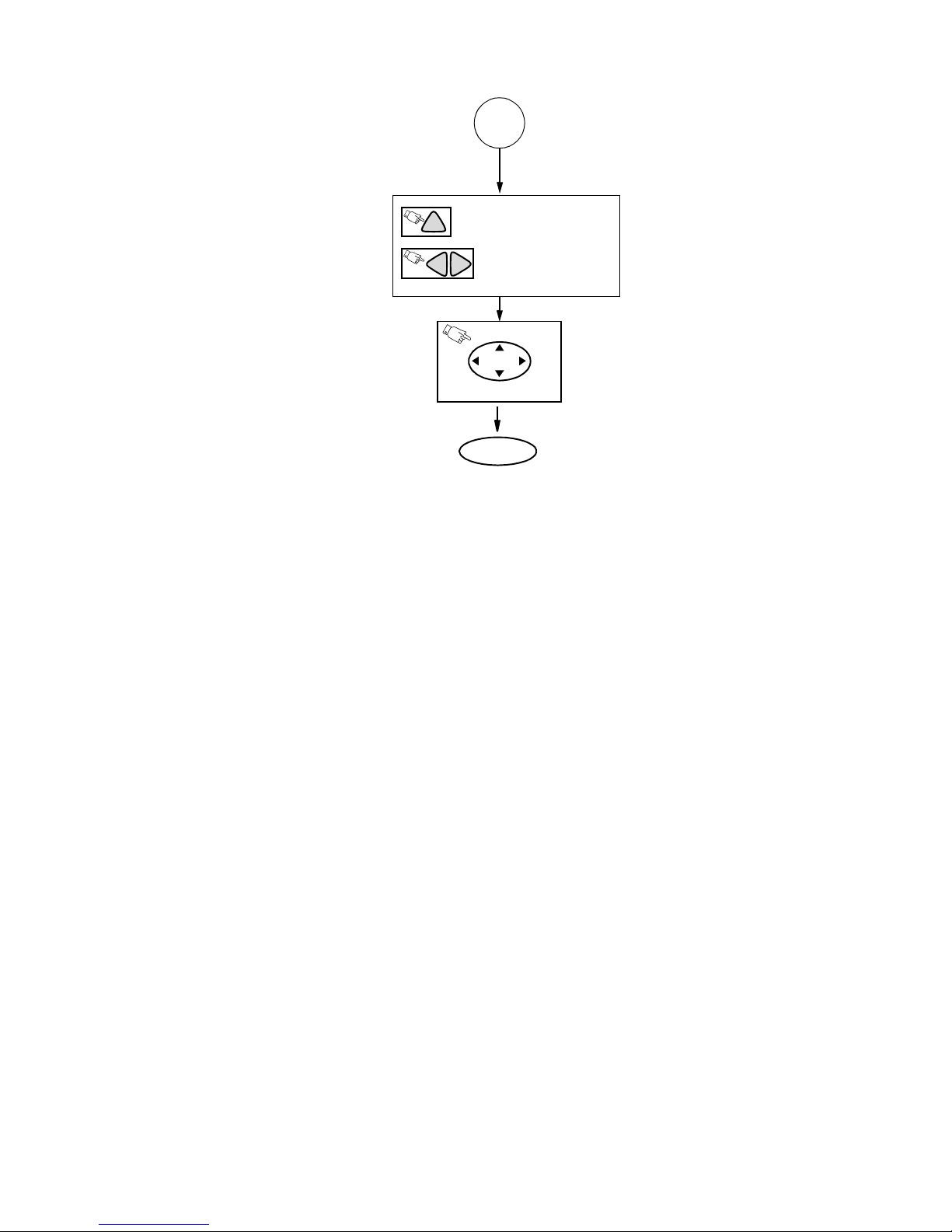
Instructional Flow Chart for Serviceman Mode - Continued
A
ON REMOTE CONTROL TO
CH
ADJUST
ON REMOTE TO
VOL
VOL
previous/next adjustment
ACTION
(ON REMOTE)
Press action to exit the adjustment.
EXIT
Press Action and Power on the Receiver
simultaneously for at least 2 seconds.
Figure 23. Flow Chart for Serviceman Mode (Continued).
- 23 -
 Loading...