

Page 1
ORDER NO. MTNC020203A1
B5
Service Manual
Color Television
d
e
i
S
m
i
p
l
i
f
Simplified Manual
(NA8MS)
Panasonic
Models
CT-24SX12F BP367
CT-24SX12UF BP367
CT-27SX12F AP390
CT-27SX12UF AP390
CT-27SX32F BP390
CT-27SX32UF BP390
This simplified service manual is issued to add listed models CT-27SX12F/UF and CT-27SX32F/UF to the main
service manual order No. MTNC010527C1 (CT-27SX31E) and CT-24SX12F/UF models to simplified service manual
order number MTNC010837A1 (CT-24SX11E). A set of unique schematics, unique settings and a complete parts list
are included in this manual.
Please file and use this simplified service manual together with main service manual, order No. MTNC010527C1
(CT-27SX31E) and simplified service manual order number MTNC010837A1 (CT-24SX11E).
“WARNING! This Service Manualisdesigned for experienced repair technicians only and is not designed for useby the general public.
It does not contain warnings or cautions to advise non-technical individuals of potential dangers in attempting to service a product.
Products powered by electricity should be serviced or repaired only by experienced professional technicians. Any attempt to
service or repair the product or products dealt with in this Service Manual by anyone else could result in seriousinjury or death.”
Chassis
The service technician is requiredtoreadand follow the “Safety Precautions”and“Important Safety Notice” in the Main Manual.
Copyright2002by Matsushita Electric Corporation of
America. All rights reserved. Unauthorized copying
®
and distribution is a violation of law.
Page 2
Important Safety Notice
Special components are used in this television set which are important for safety. These parts are identified on the
schematic diagram by the symbol and printed in BOLD TYPE on the replacement part list. It is essential that
these critical parts are replaced with the manufacturer’s specified replacement part to prevent X-ray radiation,
shock, fire or other hazards. Do not modify the original design without the manufacturer’s permission.
Safety Precautions
General Guidelines
An Isolation Transformer should always be used
during the servicing of a receiver whose chassis is not
isolated from AC power line. Use a transformer of
adequate power rating as this protects the technician
from accidents resulting in personal injury from
electrical shocks. It will also protect the Receiver from
being damaged by accidental shorting that may occur
during servicing.
When servicing, observe the original lead dress,
especially in the high voltage circuit. Replace all
damaged parts (also parts that show signs of
overheating.)
Always Replace Protective Devices,suchas
fishpaper, isolation resistors and capacitors, and
shields after servicing the Receiver. Use only
manufacturer’s recommended rating for fuses, circuits
breakers, etc.
High potentials are present when this Receiver is
operating. Operation of the Receiver without the rear
cover introduces danger for electrical shock. Servicing
should not be performed by anyone who is not
thoroughly familiar with the necessary precautions
when servicing high-voltage equipment.
Extreme care should be practiced when Handling the
Picture Tube. Rough handling may cause it to implode
due to atmospheric pressure. (14.7 lbs per sq. in.). Do
not nick or scratch the glass or subject it to any undue
pressure. When handling, use safety goggles and
heavy gloves for protection. Discharge the picture
tube by shorting the anode to chassis ground (not to
the cabinet or to other mounting hardware). When
discharging connect cold ground (i.e. dag ground lead)
to the anode with a well insulated wire or use a
grounding probe.
Avoid prolonged exposure at close range to unshielded
areas of the picture tube to prevent exposure to
X-ray radiation.
The Test Picture Tube used for servicing the chassis
at the bench should incorporate safety glass and
magnetic shielding. The safety glass provide shielding
for the tube viewing area against X-ray radiation as
well as implosion. The magnetic shield limits the X-ray
radiation around the bell of the picture tube in addition
to the restricting magnetic effects. When using a
picture tube test jig for service, ensure that the jig is
capable of handling 50kV without causing
X-ray radiation.
Before returning a serviced receiver to the owner,
the service technician must thoroughly test the unit to
ensure that is completely safe to operate. Do not use a
line isolation transformer when testing.
Leakage Current Cold Check
Unplug the AC cord and connect a jumper between the
two plug prongs.
Measure the resistance between the jumpered AC plug
and expose metallic parts such as screwheads,
antenna terminals, control shafts, etc. If the exposed
metallic part has a return p ath to the chassis, the
reading should be between 240kΩ and 5.2MΩ. If the
exposed metallic part does not have a return path to
the chassis, the reading should be infinite.
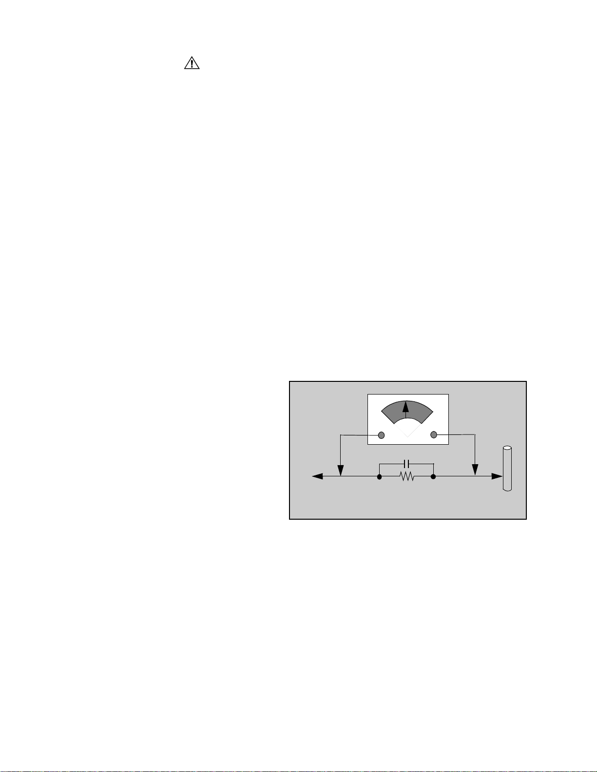
Leakage Current Hot Check (Fig. 1)
Plug the AC cord directly into the AC outlet. Do not use
an isolation transformer during the check.
Connect a 1.5kΩ 10 watt resistor in parallel with a
0.15µF capacitor between an exposed metallic part
and ground. Use earth ground, for example a
water pipe.
Using a DVM with a 1000 ohms/volt sensitivity or
higher, measure the AC potential across the resistor.
Repeat the procedure and measure the voltage
present with all other exposed metallic parts.
Verify that any potential does not exceed 0.75 volt
RMS. A leakage current tester (such a Simpson Model
229, Sencore Model PR57 or equivalent) may be used
in the above procedure, in which case any current
measure must not exceed 0.5 milliamp. If any
measurement is out of the specified limits, there is a
possibility of a shock hazard and the Receiver must be
repaired and rechecked before it is returned to the
customer.
AC VOLTMETER
COLD
WATER
PIPE
(GROUND)
0.15µF
TO INSTRUMENT’S
EXPOSED METAL
PARTS
1500Ω,10 W
Figure 1. Hot Check Circuit
X-ray Radiation
WARNING: The potential source of X-ray radiation in the
TV set is in the High Voltagesection and the picture tube.
Note: It is important to use an accurate, calibrated
high voltage meter.
Set the brightness, picture, sharpness and color
controls to Minimum. Measure the High Voltage. The
high voltage should be 30.55 ± 1.25kV. If the upper
limit is out of tolerance, immediate service and
correction is required to insure safe operation and to
prevent the possibility of premature component failure.
-2-
Page 3
About lead free solder (PbF)
component
Note: Lead is listed as (Pb) in the periodic table of elements.
In the information below, Pb will refer to Lead solder, and PbF will refer to Lead Free Solder.
The Lead Free Solder used in our manufacturing process and discussed below is (Sn+Ag+Cu).
That is Tin (Sn), Silver (Ag) and (Cu) although other types are available.
This model uses Pb Free solder in it’s manufacture due to environmental conservation issues. For
service and repair work, we’d suggest the use of Pb free solder as well, although Pb solder may be
used.
PCBs manufactured using lead free solder will have the PbF within a leaf Symbol stamped on the
back of PCB.
Caution
• Pb free solder has a higher melting point than standard solder. Typically the melting
point is 50 ~ 70 °F(30~40°C) higher. Please use a high temperature soldering iron
and set it to 700 ± 20 °F(370± 10 °C).
• Pb free solder will tend to splash when heated too high (about 1100 °For600°C).
If you must use Pb solder, please completely remove a ll of the Pb free solder on the
pins or solder area before applying Pb solder. If this is not practical, be sure to heat the
Pb free solder until it melts, before applying Pb solder.
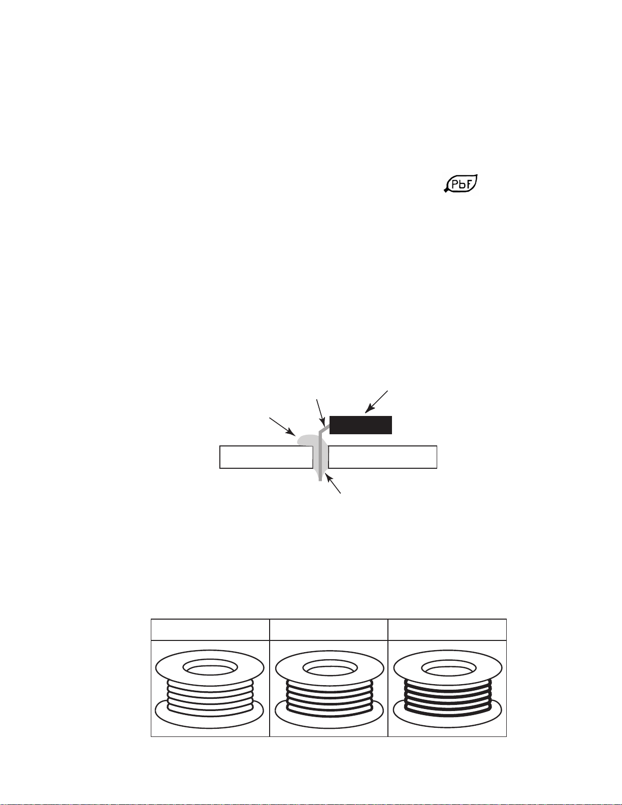
• After applying PbF solder to double layered boards, please check the component side
for excess solder which may flow onto the opposite side. (see figure below)
component
remove all of the
excess solder
pin
slice view
solder
Suggested Pb free solder
There are several kinds of Pb free solder available for purchase. This product uses Sn+Ag+Cu
(tin, silver, copper) solder. However, Sn+Cu (tin, copper), Sn+Zn+Bi (tin, zinc, bismuth) solder
canalsobeused.
0.3mm X 100g
0.6mm X 100g 1.0mm X 100g
-3-
Page 4
ImportantSafetyNotice...................2
SafetyPrecautions .................2
GeneralGuidelines................ 2
LeakageCurrentColdCheck .........2
X-rayRadiation....................2
About lead free solder . . . . . . . . . . . . ........3
ServiceNotes...........................5
Leadless Chip Component
(surfacemount).................5
ComponentRemoval................5
ChipComponentInstallation..........5
HowtoReplaceFlat-IC..............5
BoardDesignationTable..................6
ReceiverFeatureTable...................7
LocationofControls(Receiver)............7
Quick Reference Control Operation . . . . 7
QuickReference...................7
ControlOperation ..................7
Location of Controls (Remote)
EUR7613Z10,EUR7613Z30..........8
PartsList...............................9
Schematics, Voltages and waveforms
A-Board schematic
A-Board schematic
A-Board schematic
P-Board schematic
S-Boardschematic....................38
TNP2AH025CD ......22
TNP2AH025AB.......26
TNP2AH025BC ......30
....................34
-4-
Page 5
Service Notes
Note: These components are affixed with glue. Be careful not to break or damage any foil under t he
component or at the pins of the ICs when removing. Usually applying heat to the component for a
short time while twisting with tweezers will break the component loose.
Leadless Chip Component
(surface mount)
Chip components must be replaced with identical chips
due to critical foil track spacing. There are no holes in
the board to mount standard transistors or diodes.
Some chips capacitor or resistor board solder pads
may have holes through the board, however the hole
diameter limits standard resistor replacement to 1/8
watt. Standard capacitor may also be limited for the
same reason. It is recommended that identical
components be used.
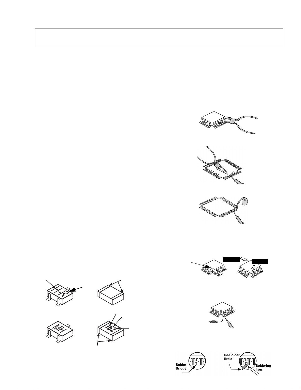
Chip resistor have a three digit numerical resistance
code - 1st and 2nd significant digits and a multiplier.
Example: 162 = 1600 or 1.6kΩ resistor, 0 = 0Ω (jumper).
Chip capacitors generally do not have the value
indicated on the capacitor. The color of the component
indicates the general range of the capacitance.
Chip transistors are identified by a two letter code. The
first letter indicates the type and the second letter, the
grade of transistor.
Chip diodes have a two letter identification code as per
the code chart and are a dual diode pack with either
common anode or common cathode. Check the parts
list for correct diode number.
Component Removal
1. Use solder wick to remove solder from component
end caps or terminal.
2. Without pulling up, carefully twist the component
with tweezers to break the adhesive.
3. Do not reuse removed leadless or chip
components since they are subject to stress
fracture during removal.
Chip Component Inst allation
1. Put a small amount of solder on the board
soldering pads.
2. Hold the chip component against the soldering
pads with tweezers or with a miniature alligator clip
and apply heat to the pad area with a 30 watt iron
until solder flows. Do not apply heat for more than
3 seconds.
TYPE
b
e
ANODES
MH DIODE
Chip Components
GRADE
c
TRANSISTOR
COMMON
CATHODE
SOLDER
CAPS
CAPACITOR
1ST DIGIT
RESISTOR
SOLDER
CAPS
2ND DIGIT
MULTIPLIER
=1600 = 1.6k
How to Replace Flat-IC
- Required Tools -
• Soldering iron • De-solder braids
• Needle nose pliers • Magnifier
• Wire cutters (sharp & small)
1. Cut the pins of a defective IC with wire cutters.
Remove IC from board. If IC is glued to the board,
heat the IC and release the IC. See Note above.
Flat IC
2. Using soldering iron and needle nose pliers
remove the IC pins from the board.
Soldering
Iron
3. Using de-soldering braid and soldering iron remove
solder from affected are on board (pads).
De-soldering
Braid
Soldering
Iron
4. Position the new Flat-IC in place (apply the pins of
the Flat-IC to the soldering pads where the pins
need to be soldered). Determine the positions of
the soldering pads and pins by correctly aligning
the polarity symbol. Solder pin #1 first, align the IC.
Polarity
symbol
Solder the pin opposite to pin #1. This will assist
positioning the IC.
5. Solder all pins to the soldering pads using a fine
tipped soldering iron.
Solder
6. Check with a magnifier for solder bridge between
the pins or for dry joint between pins and soldering
pads. To remove a solder bridge, use a de-solder
braid as shown in the figure below.
2nd solder
Soldering
Iron
1st solder
-5-
Page 6
Service Notes (Continued)
IMPORTANT: To protect against possible damage to
the solid state devices due to arcing or static discharge,
make certain that all ground wires and CTR DAG wire
are securely connected.
WARNING: This Receiver has been designed to meet
or exceed applicable safety and X-ray radiation
protection as specified by government agencies and
independent testing laboratories.
CAUTION: The power supply circuit is above earth
ground and the chassis cannot be polarized. Use an
isolation transformer when servicing the Receiver to
avoid damage to the test equipment or to the chassis.
Connect the test equipment to the proper ground ( ) or
( ) when servicing, or incorrect voltages will be
measured.
Board Table Description
BOARD
CT-24SX12F
CT-24SX12UF
CT-27SX12F
CT-27SX12UF
To maintain original product safety design standards
relative to X-ray radiation and shock and fire hazard,
parts indicated with the symbol on the schematic
must be replaced with identical parts. Order parts from
the manufacturer’s parts center using the parts
numbers shown in this service manual, or provide the
chassis number and the part reference number.
For optimum performance and reliability, all other parts
should be replaced with components of
identical specification.
CT-27SX32F
CT-27SX32UF
DESCRIPTION
A-Board TNP2AH025 CD* AB* BC* MAIN CHASSIS
C-Board TNP2AA068 AF* AD* AD* CRT BOARD
P-Board TNP2AA078 BAM* ADM* ADM* POWER SUPPLY
S-Board TNPA10190 ---* ---* AMM* SECOND TUNER
Y-Board TNPA1059 ---* ---* BC* PIP BOARD
* Note: When ordering a replacement board assembly,
append an “S” to the board number.
Example: To order the A-Board for CT-27SX32DF, the
replacement board is TNP2AH025BCS.
To order the A-Board for CT-27SX12SF, the
replacement board is TNP2AH025ABS.
-6-
Page 7
Receiver Feature Table
FEA TURE\MODEL CT-24SX12F/UF CT-27SX12F/UF CT-27SX32F/UF
Chassis NA8MS
No. of channels 181
Menu language ENG/SPAN/FR
Closed Caption X
V-Chip (USA/CANADA) X
Picture in Picture --- X
2RF --- X
75Ω input X
Remote Model No. EUR7613Z10 EUR7613Z10 EUR7613Z30
Picture tube A60LU Q085 X A68QCP893XU M68LUQ085X
Picture tube Supplier MMEC SAMSUNG MDDA
Comb Filter 3DIG
HEC/VEC VEC
VM VM
V/A norm (X=BOTH) X
CT-27SX12F/UF
and
CT-27SX32F/UF
use different
picture tubes.
Please confirm
the model
name before
placing orders.
Color Temp X
MTS/SAP/DBX X
BASS/BL/TRE Control X
AI Sound X
Surround X
SPATIALIZER/BBE BBE
Built-in audio power 7W X 2
No. of speakers 2
A/V in (rear/front) 3(2/1)
S-VHS Input (rear/front) 1/1
Component Input
(Y,Pb,Pr)
Audio Out
(FAO:F,VAO:V)
EPJ/HPJ/MISC HPJ
Dimensions mm
(WxDxH) in
Weight (kg/lbs) 35/77.16 44.5/98.1
Power source (V/Hz) 120/60
Anode voltage 30.55kV ± 1.25kV
Video input jack
Audio input jack 500mV RMS 47kΩ
626x596x733.5
27.1x19.8x23.8
1V
p-p
1
F, V
772x596x733.5
27.1x19.8x23.8
75Ω,phono jack
Specifications
are subject to
change
without notice
or obligation.
Dimensions
and weights
are
approximate.
Table 1. Receiver Features
-7-
Page 8
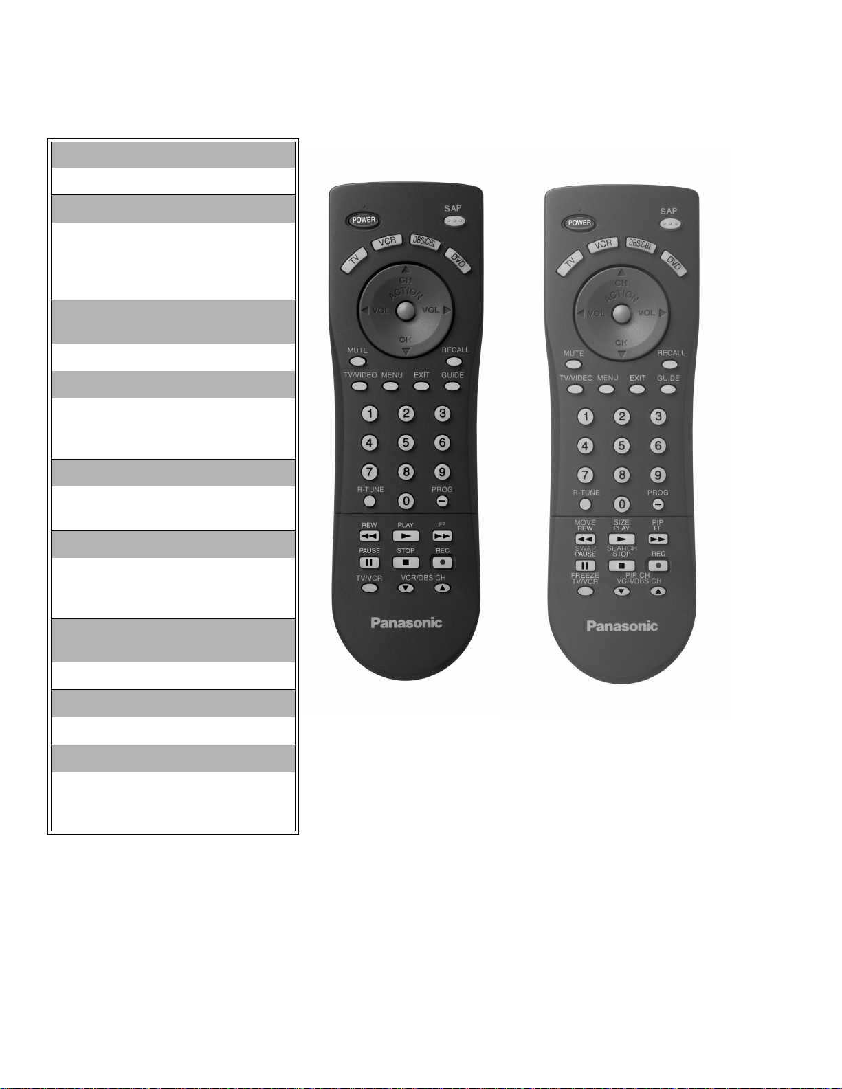
Location of Controls (Remote)
POWER Button
Press to turn ON and OFF.
MUTE Button
Press to mute sound.
A second press resumes sound.
Press also to access and delete
Closed Caption display.
VCR, DVD, LD/CD, AUX, TV, CBL,
DBS, RCVR
Component function buttons
VOL (volume) Buttons
Press to adjust TV sound level.
Use with Channel buttons to
navigate in menus.
R-TUNE (Rapid Tune) Button.
Press to switch to the previous
channel.
ACTION Button
Press to display Main Menu and
access or exit On Screen features
and Adjustment Menus.
REW,PLAY,FF,TV/VCR,STOP,
PAUSE, REC, VCR CHANNEL
Component function buttons.
TV/VIDEO Button
Press to select TV or Video input.
CH (channel) Buttons
Press to select channels.
Use with volume buttons to
navigate in menus.
Figure 2. Location of Controls (Remote).
EUR7613Z10
CT-24SX12F/UF
CT-27SX12F/UF
EUR7613Z30
CT-27SX32F/UF
-8-
Page 9
REPLACEMENT PARTS LIST
Models:CT-24SX12F/UF, CT-27SX12F/UF, CT-27SX32F/UF
Important Safety Notice: Components printed in BOLD TYPE have special characteristics important for safety. When replacing
any of these components use only manufacturer’s specified parts.
REF NO. PART NO. DESCRIPTION
CAPRISTORS
CRA801 TP00842-51 TAPING GAP TERMINAL
CRA802 TP00842-51 TAPING GAP TERMINAL
CAPACITORS
C001 ECA1CM470B CAP,E 47UF/16V
C002 TCJ2VF1H103Z CAP,C .01UF-Z-50V
C003 ECEA1HKA4R7B CAP,E 4.7UF-50V
C005 ECA1CM471B CAP,E 470UF-16V
C006 TCJ2VF1H103Z CAP,C .01UF-Z-50V
C008 TCJ2VF1H103Z CAP,C .01UF-Z-50V
C010 TCJ2VF1H103Z CAP,C .01UF-Z-50V
C013 ECA0JM101B CAP,E 100UF-6.3V
C014 TCJ2VC1H390J CAP,C 39PF-J-50V
C015 TCJ2VC1H120J CAP,C 12PF-J-50V
C017 TCJ2VC1H270J CAP,C 27PF-J-50V
C018 TCJ2VC1H270J CAP,C 27PF-J-50V
C020 ECA0JM331B CAP,E 330UF-6.3V
C021 TCJ2VF1H103Z CAP,C .01UF-Z-50V
C025 ECA1HM010B CAP,E 1UF-50V
C026 ECA1HM010B CAP,E 1UF-50V
C032 ECA1CM331B CAP,E 330UF-16V
C033 TCJ2VC1H680J CAP,C 68PF-J-50V
C034 TCJ2VC1H680J CAP,C 68PF-J-50V
C043 ECA1HM2R2B CAP,E 2.2UF-50V
C044 TCJ2VF1H103Z CAP,C .01UF-Z-50V
C047 ECA0JM102B CAP,E 1000UF-6.3V
C048 TCJ2VF1H103Z CAP,C .01UF-Z-50V
C052 TCJ2VC1H101J
C053 ECA1HM010B
C201 TCJ2VB1C104K CAP,C .1UF-K-16V
C224 TCJ2VB1C104K CAP,C .1UF-K-16V
C225 TCJ2VB1C104K CAP,C .1UF-K-16V
C226 TCJ2VB1C104K CAP,C .1UF-K-16V
C301 TCJ2VB1C104K CAP,C .1UF-K-16V
C302 TCJ2VB1C104K CAP,C .1UF-K-16V
C303 TCJ2VB1C104K CAP,C .1UF-K-16V
C307 ECA1HM0R1B CAP,E 0.1UF/50V
C309 TCJ2VC1H390J
C310 TCJ2VC1H390J CAP,C 39PF-J-50V
C314 EEANA1E1R0B
C315 EEANA1E1R0B CAP,E 1.0UF-25V
C320 TCJ2VF1H104Z CAP,C .1UF-Z-50V
C321 TCJ2VB1H103K CAP,C .01UF-K-50V
C322 TCJ2VB1H103K CAP,C .01UF-K-50V
C323 TCJ2VB1H103K CAP,C .01UF-K-50V
C324 TCJ2VF1H104Z CAP,C .1UF-Z-50V
C330 ECA1AM101B CAP,E 100UF-10V
C331 TCJ2VF1H103Z CAP,C .01UF-Z-50V
CAP,C 100PF-J-50V
CT-27SX12F/UF, CT-27SX32F/UF
CAP,E 1UF-50V
CT-27SX12F/UF, CT-27SX32F/UF
CAP,C 39PF-J-50V
CT-27SX32F/UF
CAP,E 1.0UF-25V
CT-27SX32F/UF
REF NO. PART NO. DESCRIPTION
C337 ECA1HM2R2B CAP,E 2.2UF-50V
C342 ECA1HM010B CAP,E 1UF-50V
C351 TACCV470T50V CAP,C 47PF/50V
C352 TACCV330T50V CAP,C 33PF/50V
C353 TACCV330T50V CAP,C 33PF/50V
C358 ECQB1H473JF3 CAP,P .047UF-J-50V
C359 ECQM4104KZB CAP,P .10UF-K-400V
C368 ECQV1H224JL3 CAP,P .22UF-J-50V
C370 ECKW3D102KBN CAP,C .001UF-K-2KVDC
C371 ECEA1HN010UB
C373 ECA2EHG100B CAP,E10UF-250V
C377 ECA1CM221B CAP,E 10UF-16V
C401 TCJ2VB1C104K CAP,C .1UF-K-16V
C402 TCJ2VB1H102K CAP,C 1000PF-K-50V
C403 ECA1HM010B CAP,E 1UF-50V
C404 ECA1HM010B CAP,E 1UF-50V
C405 ECSF1EE105VB CAP,E 1.0UF-25V
C407 ECA1HM220B CAP,E 22UF-50V
C409 TCJ2VC1H101J CAP,C 100PF-J-50V
C410 TCJ2VB1C104K CAP,C .1UF-K-16V
C415 TCJ2VF1H104Z CAP, C .1UF-Z-50V
C453 EEUNA1E220B CAP,E 22UF-25V
C454 ECA1HHG221B CAP,E 220UF-50V
C456 ECQB1104JF3 CAP,P .10UF-J-100V
C458 ECKR1H221KB5 CAP,C 220PF-K-50V
C459 ECQB1224KF3 CAP,P .22UF-K-100V
C460 ECA1VM221B CAP,E 220UF-35V
C461 ECA1VM470B CAP,E 47UF/35V
C462 ECA1VM221B CAP,E 220UF-35V
C463 ECQB1H103JF3 CAP,P .01UF-J-50V
C465 ECA1CM101B CAP,E 100UF/16V
C470 ECQB1H104JF3 CAP,P .10UF-J-50V
C471 ECQB1H104JF3 CAP,P .10UF-J-50V
C495 ECQB1H683JF3 CAP,P .068UF-J-50V
C504 ECQB1H222JF3 CAP, P 2200PF-J-50V
C505 TCJ2VC1H180J CAP, C 18PF-J-50V
C506 ECA1CM471B CAP,E 470UF-16V
C507 TCJ2VF1H103Z CAP,C .01UF-Z-50V
C511 ECKR2H271KB5 CAP,C 270PF-K-500W
C512 ECKR2H152KB5 CAP,C .0015UF-K-500V
C514 ECA1HMR22B CAP,E .22UF-50V
C519 TCJ2VF1H104Z CAP,C .1UF-Z-50V
C535 TCJ2VC1H120J CAP,C 12PF-J-50V
C548 ECWH16103JVB CAP,P .01UF-J-1.5KV
C549 ECQM4473JZW
C549 ECQM6333JZW
C550 ECA160V33UE CAP,E 33UF/160V
C551 ECKW3D102JBR
CAP,E 1UF/50V
CAP,P .047UF-J-400V
CAP,P .063UF-J-100V
CT-27SX12F/UF, CT-27SX32F/UF
CAP,C 1000PF-J-2KV
CT-27SX12F/UF, CT-27SX32F/UF
CT-27SX12F/UF
CT-27SX32F/UF
CT-24SX12F/UF
PARTS LIST
050-02
-9-
Parts List
Page 10

REPLACEMENT PARTS LIST
Models:CT-24SX12F/UF, CT-27SX12F/UF, CT-27SX32F/UF
Important Safety Notice: Components printed in BOLD TYPE have special characteristics important for safety. When replacing
any of these components use only manufacturer’s specified parts.
REF NO. PART NO. DESCRIPTION
C552 ECQM6332JZW
C552 ECQM6472JZW
C553 ECWF2105JBB
C553 ECWF2754JBB
C554 ECKW3D102JBR
C554 ECKW3D102KBR
C555 ECA160V33UE CAP,E 33UF/160V
C556 ECWH20102JVY
C556 ECWH20152JVY
C557 ECA1CM100B CAP,E 10UF-16V
C558 ECKW3D561JBR CAP,C 560PF-J-2KV
C559 ECKW3D681KBP CAP,C 680PF-K-2KV
C560 ECKR2H102KB5 CAP,C 1000PF-K-500V
C561 ECQB1H273JF3 CAP,P .027UF-J-50V
C562 ECKR2H471KB5 CAP,C 470PF-K-500W
C563 ECA1EM102E CAP,E 1000UF-25V
C564 ECKR2H471KB5 CAP,C 470PF-K-500W
C565 ECA1EM102E CAP,E 1000UF-25V
C566 ECKR2H471KB5 CAP,C 470PF-K-500W
C567 ECA1CM471B CAP,E 470UF-16V
C569 ECWF2274JBB
C569 ECWF2304JBB
C570 ECA2EM220E CAP,E 22UF-250V
C571 ECKR2H102KB5 CAP,C 1000PF-K-500V
C572 ECWF2334JBB CAP,P .33UF-J-200V
C573 ECQE2474KFW CAP,P .47UF-K-200V
C580 ECA1HM4R7B CAP,E 4.7UF-50V
C581 ECA1CM471B CAP,E 470UF-16V
C582 ECA1CM101B CAP,E 100UF/16V
C583 ECA1CM100B CAP,E 10UF-16V
C593 ECEA1HNR47UB CAP,E.47UF-50V
C595 ECA1HM100B CAP,E 10UF/50V
C601 TCJ2VF1H103Z CAP, C .01UF-Z-50V
C603 ECQB1H223JF3 CAP,P .022UF-J-50V
C616 TCJ2VB1C104K CAP,C .1UF-K-16V
PARTS LIST
C619 TCJ2VF1H103Z CAP, C .01UF-Z-50V
C628 TCJ2VC1H151J CAP,C 150PF-J-50V
C632 TCJ2VB1H103K CAP,C .01UF-K-50V
C641 ECA1CM100B CAP,E 10UF-16V
C701 TCJ2VF1H103Z CAP, C .01UF-Z-50V
C750 TCJ2VC1H181J CAP,C 180PF-J-50V
C751 ECQE1335KFB CAP,P 3.3UF -K-100V
C752 ECA1VM470B CAP,E 47UF/35V
CAP,P .63UF-J-100V
CT-24SX12F/UF, CT-27SX12UF
CAP,C 4700PF-K-600V
CT-27SX12F, CT-27SX32F/UF
CAP,M 1UF-J-200V
CT-27SX12F/UF, CT-27SX32F/UF
CAP,M .27UF-J-200V
CAP,C 1000PF-J-2KV
CT-27SX12F/UF, CT-27SX32F/UF
CAP,C 1000PF-K-2KV
CAP,P 1000PF-J-2KV
CAP,P 1500PF-J-2KV
CT-27SX12F/UF, CT-27SX32F/UF
CAP,M .27UF-J-200V
CT-27SX12F/UF, CT-27SX32F/UF
CAP,M .3UF-J-200V
CT-24SX12F/UF
CT-24SX12F/UF
CT-24SX12F/UF
CT-24SX12F/UF
REF NO. PART NO. DESCRIPTION
C753 ECQB1H222JF3 CAP,P 2200PF-J-50V
C754 TCJ2VB1H332K CAP,C .0033UF-K-50V
C755 TCJ2VB1H273K CAP,C .027UF-K-50V
C756 ECKR2H332KB5 CAP,C 3300PF-K-550V
C757 TCJ2VB1H223K
C757 TCJ2VB1H682K
C763 ECKR3A121KBP CAP,C 120PF-K-1KV
C801 ECKWAE472ZED CAP,C 4700PF-Z-500V
C802 ECKWAE472ZED CAP,C 4700PF-Z-500V
C803 ECKWAE472ZED CAP,C 4700PF-Z-500V
C804 ECKWAE472ZED CAP,C 4700PF-Z-500V
C805 EC0S2DA561BB CAP,E 560PF-200V
C806 ECQB1H104JF3 CAP,P .10UF-J-50V
C807 ECQB1H103JF3 CAP,P .01UF-J-50V
C809 ECKR3A222KBP CAP,C .0022UF-K-1KV
C812 ECQU2A224MVA CAP,P .22UF-M -250VAC
C813 ECQU2A153MVA CAP,P .015UF-M-250VAC
C814 ECQU2A153MVA CAP,P .015UF-M -250VAC
C815 ECQB1H104JF3 CAP,P .10UF-J-50V
C816 ECQB1H473JF3 CAP,P .047UF-J-50V
C817 ECQU2A224MVA CAP,P .22UF-M-250VAC
C818 ECQB1H103JF3 CAP,P .01UF-J-50V
C819 ECKCNB102MB CAP,C 1000PF-M-250V
C820 ECKCNB102MB CAP,C 1000PF-M-250V
C821 ECA1HM471E CAP,E 470UF-50V
C822 ECKR3A471KBP
C822 ECKR3A821KBP
C823 ECA1CHG101B CAP,E 100UF-16V
C824 ECKR3A152KBP
C824 ECKR3A821KBP
C825 EEUMG2C221S CAP,E 220UF-160V
C826 ECKR3A821KBP CAP,C 820PF-K-1KV
C827 ECA1CM102B CAP,E 1000UF/16V
C828 ECKR1H471KB5 CAP,C 470PF-K-50V
C831 ECKR3A221KBP CAP,C 220PF-K-1KV
C832 ECKR3A471KBP CAP,C 470PF-K-1KV
C833 ECA1HM4R7B CAP,E 4.7UF-50V
C835 ECA1EM101B CAP,E 100UF-25V
C901 TCJ2VF1H103Z CAP,C .01UF-Z-50V
C902 TCJ2VC1H561J CAP,C 560PF-J-50V
C904 ECKR1H103ZF5 CAP,C .01UF-Z-50V
C952 ECA1HM100B CAP,E 10UF/50V
C953 ECKR1H103ZF5 CAP,C .01UF-Z-50V
C958 ECA2CM470E CAP,E 47UF-160V
C959 ECKW2H103ZF7 CAP,C.01UF-Z-500V
C960 ECCR2H151J5 CAP,C150-500V
CAP,C .022UF-K-50V
CT-27SX12F, CT-27SX32F/UF
CAP,C 6800PF-K-50V
CT-24SX12F/UF, CT-27SX12UF
CAP,C 470PF-K-1KV
CT-24SX12F/UF
CAP,C 820PF-K-1KV
CT-27SX12F/UF, CT-27SX32F,/UF
CAP,C 1500PF-K- 1KVDC
CT-27SX12F/UF, CT-27SX32F/UF
CAP,C 820PF-K-1KV,
CT-24SX12F/UF
Parts List
-10-
050-02
Page 11

REPLACEMENT PARTS LIST
Models:CT-24SX12F/UF, CT-27SX12F/UF, CT-27SX32F/UF
Important Safety Notice: Components printed in BOLD TYPE have special characteristics important for safety. When replacing
any of these components use only manufacturer’s specified parts.
REF NO. PART NO. DESCRIPTION
C961 ECA2AM100B CAP,E 10UF-100V
C962 ECKW2H103ZF7 CAP,C.01UF-Z-500V
C963 ECCR1H151J5 CAP DISC 150-5-50V
C964 ECA1CHG101B CAP,E 100UF-16V
C966 ECA1CHG101B CAP,E 100UF-16V
C967 ECA1CM221B CAP,E 10UF-16V
C968 ECKR1H103ZF5 CAP,C .01UF-Z-50V
C969 ECKR1H103ZF5 CAP,C .01UF-Z-50V
C971 TACCW222T50V CAP,C 2200PF/50V
C1801 TCJ2VF 1H103Z
C1802 ECQV 1H154JL3
C1803 ECA1HMR22B CAP,E .22UF-50V
C1804 ECEA1HK AR22B CAP,E .22UF-50V
C1805 TCJ2VF 1H333Z
C1806 TCJ2VF 1H103Z
C1807 ECA1CM470B CAP,E 47UF/16V
C1808 TCJ2VF 1H103Z
C1809 ECA1CM470B CAP,E 47UF/16V,
C1810 TCJ2VF 1H104Z
C1811 TCJ2VF 1H103Z
C1812 TCJ2VF 1H103Z
C1813 TCJ2VF 1H103Z
C1814 ECA1CM470B CAP,E 47UF/16V
C1815 TCJ2VF 1H104Z
C1816 TCJ2VF 1H103Z
C1817 TCJ2VF 1H103Z
C1818 ECA1CM100B CAP,E 10UF-16V
C1819 TCJ2VF 1H104Z
C1820 ECA1CM470B CAP,E 47UF/16V
C1821 TCJ2VC1H150J
C1822 TCJ2VC1H120J
C1823 TCJ2VC1H680J
C1826 TCJ2VF 1H103Z
C1827 TCJ2VF 1H103Z
C1828 TCJ2VF 1H103Z
C1829 TCJ2VF 1H104Z CAP,C .1UF-Z-50V
CAP,C .01UF-Z-50V
CT-27SX32F/UF
CAP,P.15UF-J-50V
CT-27SX32F/UF
CT-27SX32F/UF
CT-27SX32F/UF
CAP,C .033UF-Z-50V
CT-27SX32F/UF
CAP,C .01UF-Z-50V
CT-27SX32F/UF
CT-27SX32F/UF
CAP,C .01UF-Z-50V
CT-27SX32F/UF
CT-27SX32F/UF
CAP,C .1UF-Z-50V
CT-27SX32F/UF
CAP,C .01UF-Z-50V
CT-27SX32F/UF
CAP,C .01UF-Z-50V
CT-27SX32F/UF
CAP,C .01UF-Z-50V
CT-27SX32F/UF
CT-27SX32F/UF
CAP,C .1UF-Z-50V
CT-27SX32F/UF
CAP,C .01UF-Z-50V
CT-27SX32F/UF
CAP,C .01UF-Z-50V
CT-27SX32F/UF
CT-27SX32F/UF
CAP,C .1UF-Z-50V
CT-27SX32F/UF
CT-27SX32F/UF
CAP,C 15PF-J-50V
CT-27SX32F/UF
CAP,C 12PF-J-50V
CT-27SX32F/UF
CAP,C 68PF-J-50V
CT-27SX32F/UF
CAP,C .01UF-Z-50V
CT-27SX32F/UF
CAP,C .01UF-Z-50V
CT-27SX32F/UF
CAP,C .01UF-Z-50V
CT-27SX32F/UF
CT-27SX32F/UF
REF NO. PART NO. DESCRIPTION
C1830 TCJ2VC1H560J CAP,C 56PF-J-50V,
C1831 TCJ2VF1H104Z
C1832 TCJ2VF1H104Z
C1833 TCJ2VF1H104Z
C1835 ECA1CM100B CAP,E 10UF-16V,
C1836 TCJ2VC1H680J
C1837 TCJ2VF1H104Z
C1839 TCJ2VC1H680J
C1840 TCJ2VC1H680J
C2105 ECA0JM101B
C2106 ECA1HMR47B CAP,E .47UF-50V
C2108 ECA1CM330B CAP,E 33UF-16V
C2109 TCJ2VF1H103Z
C2111 ECEA1HFSR22B CAP,E .22UF-50V,
C2114 TCJ2VF1H103Z
C2115 ECA1HM100B CAP,E 10UF/50V,
C2116 TCJ2VF1H103Z
C2118 TCJ2VC1H270J
C2119 TCJ2VF1H103Z
C2120 ECEA1HFSR47B CAP,E .47UF-50V,
C2121 TCJ2VF1H103Z
C2123 TCJ2VC1H270J
C2124 TCJ2VF1H103Z
C2125 ECA1CM100B CAP,E 10UF-16V
C2126 ECA1HMR22B CAP,E .22UF-50V
C2202 ECA1HM2R2B CAP,E 2.2UF-50V
C2203 ECA1HM4R7B CAP,E 4.7UF-50V
C2204 AP106K016CAE CAP,T 10UF/16V
C2205 ECA1HM010B CAP,E 1UF-50V
C2206 ECQB 1H223JF3 CAP,P .022UF-J-50V
C2207 AP335K016CAE CAP,T 3.3UF/16V
C2208 TCJ2VB1C104K CAP,C .1UF-K-16V
C2209 TCJ2VB1C104K CAP,C .1UF-K-16V
C2210 TCJ2VB1C104K CAP,C .1UF-K-16V
C2211 ECA1CM100B CAP,E 10UF-16V
C2212 ECQB 1H473JF3 CAP,P .047UF-J-50V
C2215 ECA0JM101B CAP,E 100UF-6.3V
C2218 ECA1HMR47B CAP,E .47UF-50V
C2220 TCJ2VC1H100D CAP,C 10PF-J-50V
CAP,C .1UF-Z-50V
CAP,C .1UF-Z-50V
CAP,C .1UF-Z-50V
CAP,C 68PF-J-50V
CAP,C .1UF-Z-50V
CAP,C 68PF-J-50V
CAP,C 68PF-J-50V
CAP,E 100UF-6.3V
CAP,C .01UF-Z-50V
CAP,C .01UF-Z-50V
CAP,C .01UF-Z-50V
CAP,C 27PF-J-50V
CAP,C .01UF-Z-50V
CAP,C .01UF-Z-50V
CAP,C 27PF-J-50V
CAP,C .01UF-Z-50V
CT-27SX32F/UF
CT-27SX32F/UF
CT-27SX32F/UF
CT-27SX32F/UF
CT-27SX32F/UF
CT-27SX32F/UF
CT-27SX32F/UF
CT-27SX32F/UF
CT-27SX32F/UF
CT-27SX32F/UF
CT-27SX32F/UF
CT-27SX32F/UF
CT-27SX32F/UF
CT-27SX32F/UF
CT-27SX32F/UF
CT-27SX32F/UF
CT-27SX32F/UF
CT-27SX32F/UF
CT-27SX32F/U
CT-27SX32F/UF
CT-27SX32F/UF
CT-27SX32F/UF
CT-27SX32F/UF
CT-27SX32F/UF
CT-27SX32F/UF
F
PARTS LIST
050-02
-11-
Parts List
Page 12

REPLACEMENT PARTS LIST
Models:CT-24SX12F/UF, CT-27SX12F/UF, CT-27SX32F/UF
Important Safety Notice: Components printed in BOLD TYPE have special characteristics important for safety. When replacing
any of these components use only manufacturer’s specified parts.
REF NO. PART NO. DESCRIPTION
C2302 ECA1HM010B CAP,E 1UF-50V
C2305 ECA1HM010B CAP,E 1UF-50V
C2307 ECA1EM102E CAP,E 1000UF-25V
C2308 ECA1HM101B CAP,E 100UF-50V
C2311 ECA1HM010B CAP,E 1UF-50V
C2312 ECA1EM102E CAP,E 1000UF-25V
C2313 ECA1VM102E CAP,E 1000UF-35V
C2314 ECA1CM101B CAP,E 100UF/16V
C2331 ECA1HM010B CAP,E 1UF-50V
C2332 ECA1HM010B CAP,E 1UF-50V
C2333 ECA1EM100B CAP,E 10UF-25V
C2334 ECA1EM100B CAP,E 10UF-25V
C2335 ECA1HM010B CAP,E 1UF-50V
C2336 ECA1HM010B CAP,E 1UF-50V
C2337 ECA1CM470B CAP,E 47UF/16V
C2431 ECA1HM010B CAP,E 1UF-50V
C2432 ECA1HM010B CAP,E 1UF-50V
C2433 TCJ2YC1H222J CAP,C .022UF-J-50V
C2437 TCJ2VB1H333K CAP,C .033UF-K-50V
C2438 TCJ2VB1H102K CAP,C 1000PF-K-50V
C2444 TCJ2VB1C104K CAP,C .1UF-K-16V
C2445 TCJ2VB1C104K CAP,C .1UF-K-16V
C2449 TCJ2VB1H333K CAP,C .033UF-K-50V
C2450 TCJ2VB1H102K CAP,C 1000PF-K-50V
C2451 ECEA1CN100UB CAP,E 10UF-16V
C2459 TCJ2VB1H333K CAP,C .033UF-K-50V
C2460 TCJ2VB1H333K CAP,C .033UF-K-50V
C2461 ECA1HM4R7B CAP,E 4.7UF-50V
C2462 ECA1HM4R7B CAP,E 4.7UF-50V
C2463 ECEA1CN100UB CAP,E 10UF-16V
C2464 TCJ2VB1H333K CAP,C .033UF-K-50V
C2465 TCJ2VB1H333K CAP,C .033UF-K-50V
C2468 ECA1AM101B CAP,E 100UF-10V
C2473 ECA1HM4R7B CAP,E 4.7UF-50V
C2474 ECA1AM101B CAP,E 100UF-10V
C2475 ECA1HM4R7B CAP,E 4.7UF-50V
C3001 TCJ2VF 1H103Z CAP,C .01UF-Z-50V
C3002 ECA1AM101B CAP,E 100UF-10V
C3003 ECA1CM100B CAP,E 10UF-16V
C3004 ECA1HM010B CAP,E 1UF-50V
C3006 ECA1HM010B CAP,E 1UF-50V
C3007 ECA1CM100B CAP,E 10UF-16V
C3008 ECA1CM100B CAP,E 10UF-16V
PARTS LIST
C3009 ECA1HM010B CAP,E 1UF-50V
C3010 TCJ2VF 1H103Z CAP,C .01UF-Z-50V
C3011 ECA1HM010B CAP,E 1UF-50V
C3012 ECA1CM100B CAP,E 10UF-16V
C3013 ECA1CM100B CAP,E 10UF-16V
C3014 ECA1HM010B CAP,E 1UF-50V
C3016 ECA1HM010B CAP,E 1UF-50V
C3017 ECEA1CK A100B CAP,E 10UF-16V,
Parts List
CT-27SX32F/UF
REF NO. PART NO. DESCRIPTION
C3018 ECA1CM100B CAP,E 10UF-16V
C3019 ECA1CM100B CAP,E 10UF-16V
C3020 ECA1HM010B CAP,E 1UF-50V
C3021 TCJ2VF1H103Z CAP,C .01UF-Z-50V
C3022 ECA1HM010B CAP,E 1UF-50V
C3023 ECA1CM100B CAP,E 10UF-16V
C3024 ECA1CM100B CAP,E 10UF-16V
C3024 ECQB 1H104JF3
C3025 TCJ2VF1H103Z CAP,C .01UF-Z-50V
C3026 TCJ2VC1H820J
C4301 ECA0JM331B
C4304 ECEA1CK A100B CAP,E 10UF-16V
C4307 ECEA1CKN 100B CAP,E 10UF-16V
C4313 TCJ2VB1H561K
C4314 ECA1HMR47B CAP,E .47UF-50V
C4315 TCJ2VB1H152K
C4316 ECA0JM331B
C4317 TCJ2VF1H103Z
C4319 TCJ2VC1H391J
C4320 TCJ2VB1H681K
C4801 ECA1HM4R7B
C4803 ECQV 1H334JL3
C4804 ECQV 1H334JL3
C4805 ECA1VM470B
C4806 ECA1HM4R7B
C4808 ECA1HM330B
C6501 ECA0JM101B CAP,E 100UF-6.3V
C6502 TCJ2VF1H103Z CAP,C .01UF-Z-50V
C6503 TCJ2VF1H104Z CAP,C .1UF-Z-50V
C6504 ECA1AM470B CAP,E 47UF-10V
C6505 TCJ2VF1H103Z CAP,C .01UF-Z-50V
C6506 TCJ2VF1H103Z CAP,C .01UF-Z-50V
C6507 ECA1HMR47B CAP,E .47UF-50V
C6508 TCJ2VF1H103Z CAP,C .01UF-Z-50V
C6509 ECA1CM470B CAP,E 47UF/16V
C6510 TCJ2VF1H104Z CAP,C .1UF-Z-50V
C6511 TCJ2VF1H104Z CAP,C .1UF-Z-50V
C6512 ECA1CM470B CAP,E 47UF/16V
C6513 TCJ2VF1H103Z CAP,C .01UF-Z-50V
C6514 TCJ2VF1H103Z CAP,C .01UF-Z-50V
CAP,P .10UF-J-50V
CT-27SX12F/UF, CT-27SX32F/UF
CAP,C 82PF-J-50V
CAP,E 330UF-6.3V
CAP,C 560PF-K-50V
CAP,C 1500PF-K-50V
CAP,E 330UF-6.3V
CAP,C .01UF-Z-50V
CAP,C 390PF-J-50V
CAP,C 680PF-K-50V
CAP,E 4.7UF-50V
CT-27SX12F/UF , CT-27SX32F/UF
CAP,P .33UF-J-50V
CT-27SX12F/UF , CT-27SX32F/UF
CAP,P .33UF-J-50V
CT-27SX12F/UF, CT-27SX32F/UF
CAP,E 47UF/35V
CT-27SX12F/UF , CT-27SX32F/UF
CAP,E 4.7UF-50V
CT-27SX12F/UF,
CAP,E 33UF-50V
CT-27SX12F/UF , CT-27SX32F/UF
-12-
CT-24SX12F/UF
CT-27SX32F/UF
CT-27SX32F/UF
CT-27SX32F/UF
CT-27SX32F/UF
CT-27SX32F/UF
CT-27SX32F/UF
CT-27SX32F/UF
CT-27SX32F/UF
CT-27SX32F/UF
CT-27SX32F/UF
CT-27SX32F/UF
CT-27SX32F/UF
050-02
Page 13

REPLACEMENT PARTS LIST
Models:CT-24SX12F/UF, CT-27SX12F/UF, CT-27SX32F/UF
Important Safety Notice: Components printed in BOLD TYPE have special characteristics important for safety. When replacing
any of these components use only manufacturer’s specified parts.
REF NO. PART NO. DESCRIPTION
C6515 TCJ2VF1H104Z CAP,C .1UF-Z-50V
C6516 ECA1CM470B CAP,E 47UF/16V
C6517 TCJ2VC1H181J CAP,C 180PF-J-50V
C6518 TCJ2VF 1H103Z CAP,C .01UF-Z-50V
C6519 TCJ2VF1H103Z CAP,C .01UF-Z-50V
C6520 ECA1CM470B CAP,E 47UF/16V
C6525 TCJ2VC1H120J CAP,C 12PF-J-50V
C6526 TCJ2VC1H270J CAP,C 27PF-J-50V
C6532 TCJ2VF1H103Z CAP,C .01UF-Z-50V
C6569 TCJ2VC1H180J CAP,C 18PF-J-50V
C6570 ECA1HM010B CAP,E 1UF-50V
C6572 ECEA1CN470UB CAP,E 47UF-16V
DIODES
D001 MA165TA5VT DIODE, SWITCHING
D002 MA165TA5VT DIODE, SWITCHING
D003 MA4056MTA DIODE
D006 MA4330HTA DIODE
D010 MA4100LTA DIODE
D014 MA165TA5VT DIODE, SWITCHING
D015 MA700ATA DIODE
D051 MA4056MTA DIODE
D052 MA165TA5VT
D240 MA165TA5VT DIODE, SWITCHING
D354 MA165TA5VT DIODE, SWITCHING
D355 MA165TA5VT DIODE, SWITCHING
D356 MA165TA5VT DIODE, SWITCHING
D360 ERA22-04V3 DIODE, SILICONE
D361 ERA22-04V3 DIODE, SILICONE
D362 ERA22-04V3 DIODE, SILICONE
D363 MA165TA5VT DIODE, SWITCHING
D375 MA165TA5VT DIODE, SWITCHING
D451 ERA15-02V3 DIODE
D455 MA165TA5VT DIODE, SWITCHING
D456 MA165TA5VT DIODE, SWITCHING
D457 MA165TA5VT DIODE, SWITCHING
D459 MA165TA5VT DIODE, SWITCHING
D551 ERD07-15E DIODE
D552 RU3NLFA1 DIODE
D553 MA4062LTVTA DIODE, ZENER
D554 MA4270MTA DIODE
D556 MA4360HTA DIODE, Z ENE R
D561 MA165TA5VT DIODE, SWITCHING
D562 D1NL40V70 DIODE
D563 TVSRU2NV1 DIODE, SILICONE
D564 TVSRU 2NV1 DIODE, SILICONE
D570 D1NL40V70 DIODE
D575 MA165TA5VT DIODE, SWITCHING
D580 D1NL40V70 DIODE
D753 AU01ZV0 DIODE
D754 MA165TA5VT DIODE, SWITCHING
DIODE, SWITCHING
CT-27SX12F/UF, CT-27SX32F/UF
REF NO. PART NO. DESCRIPTION
D801 GP15KL-042 DIODE
D802 GP15KL-042 DIODE
D803 GP15KL-042 DIODE
D804 GP15KL-042 DIODE
D806 TAP2AA0001 PTC 5-OHM
D807 D1NL20UV70 DIODE
D808 D1NL20UV70 DIODE
D809 MA4036MTA DIODE
D810 MA4150MTA DIODE
D811 MA4270MTA DIODE
D812 D1NL20UV70 DIODE
D813 TMPG10G3 DIODE
D814 TMPG10G3 DIODE
D822 RU3YX-MV1 DIODE, RECTIFIER
D823 S3L60P154004 DIODE
D824 D1NL20UV70 DIODE
D825 MA165TA5VT DIODE, SW ITCHING
D826 MA4180HTA DIODE
D837 MA4068MTA DIODE, ZENE R
D838 MA4150MTA DIODE
D839 MA165TA5VT DIODE, SW ITCHING
D840 D1NL20UV70 DIODE
D845 MA165TA5VT DIODE, SW ITCHING
D2101 MA3330MTX DIODE
D2302 MA165TA5VT DIODE, SWITCHING
D2303 MA165TA5VT DIODE, SWITCHING
D2318 MA165TA5VT DIODE, SWITCHING
D3007 MA4110MTA DIODE, ZENER
D3008 MA4110MTA DIODE, ZENER
D3018 ERDS2T J750T
D3023 MA4110MTA DIODE, ZENER
D3024 MA4110MTA DIODE, ZENER
D3025 MA4110MTA DIODE, ZENER
D3026 MA4110MTA DIODE, ZENER
D3027 MA4110MTA DIODE, ZENER
D3028 MA4110MTA DIODE, ZENER
D3029 MA4110MTA DIODE, ZENER
D3030 MA4110MTA DIODE, ZENER
D4301 MA3036HT X DIODE
RES,C 75-J-1/4W
CT-27SX32F/UF
CT-27SX12F/UF
CT-27SX32F/UF
CT-27SX32F/UF
FUSES
F801 XBA2A00101 FUSE 6.3A 125V
INTEGRED CIRCUITS
IC001 MN101C46FTG MPU
IC002 C3EAFC000011 EEPROM
IC003 PIC-37042SR REMOTE SENSOR
IC005 PQ1R33 STNDBY REG.
IC006 PST9128NR RESET
IC101 TA1310BN VCJ
IC351 TDA6103Q-N3 RGB OUT AMP.
IC451 LA78045 VERTICAL OUT
PARTS LIST
050-02
-13-
Parts List
Page 14

REPLACEMENT PARTS LIST
Models:CT-24SX12F/UF, CT-27SX12F/UF, CT-27SX32F/UF
Important Safety Notice: Components printed in BOLD TYPE have special characteristics important for safety. When replacing
any of these components use only manufacturer’s specified parts.
REF NO. PART NO. DESCRIPTION
IC551 AN78M09LB 9V REG.
IC552 AN7805LB 5V REG.
IC750 NJM4565L HORIZONTAL
IC801 PC123FY2 OPTHO COUPLER
IC802 PC123FY2 OPTHO COUPLER
IC820 UPC1093J-T ZENER REG.
IC1801 M65617SP INT CKT
IC2101 AN5170K MTS
IC2201 AN5849S-E1V AUDIO AMP.
IC2301 AN5277 VAO AMP.
IC2331 NJM4565L SOUND PROCESSOR
IC2451 BH3868CFS-E2 A/V SWITCH
IC3001 M52790SP A/V SWITCH
IC3002 MM1502XNRE PIP SWITCH
IC4801 PUB4301
IC4802 AN6564
IC6501 TC90A49P 3L COMB FILTER
GEOMAGNETIC CIRCUIT
CT-27SX12F/UF, CT-27SX32F/UF
GEOMAGNETIC CIRCUIT
CT-27SX12F/UF,
COILS
J41 EXCELDR35V FERRITE BEAD
J143 TLTABT2R2K
J146 EXCELSA35T FERRITE BEAD
J152 EXCELSA39V FERRITEBEAD
J159 TLTABT470K COIL, PEAKING 47UH
J329 EXCELSA39V FERRITEBEAD
J338 EXCELSA39V FERRITE BEAD
L002 ELESN180JA COIL, PEAKING 18UH
L003 TLTABT2R2K COIL, PEAKING 2.2UH
L004 TLTABT2R2K COIL, PEAKING 2.2UH
L005 ELESN330JA COIL, PEAKING 33UH
L006 EXCELSA35T FERRITE BEAD
L008 TLTABT101K COIL, PEAKING
L010 TLTABT2R2K COIL, PEAKING 2.2UH
L011 TLTABT2R2K COIL,PEAKING 2.2UH
L012 TLTABT2R2K COIL, PEAKING 2.2UH
L013 TLTABT2R2K COIL, PEAKING 2.2UH
L100 TLTABT2R2K
L157 TLTABT101K COIL, PEAKING
L301 TLTABT470K COIL, PEAKING 47UH
L302 ELESN120JA COIL, PEAKING 12UH
L319 TLTABT101K COIL, PEAKING
PARTS LIST
L519 ELESN101JA COIL, PEAKING 100UH
L551 ELH5L6118
L551 ELH5L6120 COIL
L553 EXCELSA39V FERRITE BEAD
L556 ELC18B801E COIL
L559 TLUADNB682K COIL
L601 TLUABTA560K CO IL, PEAKING 56UH
COIL, PEAKING 2.2UH
COIL, PEAKING 2.2UH
CT-27SX12F/UF, CT-27SX32F/UF
COIL
CT-27SX32F/UF
CT-27SX32F/UF
CT-27SX32F/UF
CT-27SX32F/UF
CT-27SX32F/UF
CT-27SX12F/UF
CT-27SX32F/UF
CT-24SX12F/UF
REF NO. PART NO. DESCRIPTION
L706 EXCELSA35T FERRITE BEAD
L751 ELC18B681E
L751 ELC18B801E COIL, C T-24SX12F CT-24SX12UF
L752 TALL13N103JB COIL
L801 ELF20N020A COIL, 2UH
L802 G0C681Z00001 COIL
L803 EXCELSA26T FERRITE BEAD
L805 TALL08T220KA TRANSFORMER, LINE FILTER
L807 EXCELSA39V FERRITE BEAD
L808 ELF20N020A COIL, 2UH
L809 EXCELSA39V FERRITE BEAD
L951 EXCELSA24T FERRITE BEAD
L953 EXCELSA24T FERRITE BEAD
L954 EXCELSA24T FERRITE BEAD
L955 EXCELSA24T FERRITE BEAD
L1801 ELESN1R5KA
L1803 ELESN2R2KA
L1804 ELESN150JA
L1806 ELESN1R0KA
L1807 ELESN1R0KA
L1808 EXCELDR25V FERRITE BEAD
L2103 ELESN150KA
L2106 ELESN560KA
L2109 EIV7EN053B COIL, VCO
L4301 ELESN3R9KA
L6503 ELESN330JA COIL, PEAKING 33UH
L6504 EXCELSA35V FERRITEBEAD
L6505 EXCELS A35V FERRITE BEAD
L6507 ELESN150JA COIL, PEAKING 15UH
L6509 EXCELS A35V FERRITE BEAD
COIL
COIL, PEAKING 1.5UH
COIL, PEAKING 2.2UH
COIL, PEAKING 15UH
COIL, PEAKING 1.0UH
COIL, PEAKING 1.0UH
COIL, PEAKING 15UH
COIL, PEAKING 56UH
COIL, PEAKING 3.9UH
CT-27SX12F/UF
CT-27SX32F/UF
CT-27SX32F/UF
CT-27SX32F/UF
CT-27SX32F/UF
CT-27SX32F/UF
CT-27SX32F/UF
CT-27SX32F/UF
CT-27SX32F/UF
CT-27SX32F/UF
CT-27SX32F/UF
CT-27SX32F/UF
TRANSISTORS
Q001 2SC1685QRSTA TRANSISTOR
Q002 2SC1685QRSTA TRANSISTOR
Q003 2SD601ARTX TRANSISTOR
Q004 2SC1685QRSTA TRANSISTOR
Q005 2SD601ARTX TRANSISTOR
Q006 2SD601ARTX
Q007 2SC1685QRSTA TRANSISTOR
Q201 2SD601ARTX TRANSISTOR
Q302 2SB709ARTX TRANSISTOR
Q303 2SD601ARTX TRANSISTOR
Q369 2SA1309ATA TRANSISTOR
Q402 2SD601ARTX TRANSISTOR
TRANSISTOR
CT-27SX12F/UF
CT-27SX32F/UF
CT-27SX32F/UF
Parts List
-14-
050-02
Page 15

REPLACEMENT PARTS LIST
Models:CT-24SX12F/UF, CT-27SX12F/UF, CT-27SX32F/UF
Important Safety Notice: Components printed in BOLD TYPE have special characteristics important for safety. When replacing
any of these components use only manufacturer’s specified parts.
REF NO. PART NO. DESCRIPTION
Q453 2SD601ARTX TRANSISTOR
Q480 2SA1309ATA TRANSISTOR
Q501 2SC3941HTA TRANSISTOR
Q515 2SD601ARTX TRANSISTOR
Q551 2SC5339LBMA1 TRANSISTOR
Q603 2SD601ARTX TRANSISTOR
Q611 2SB709ARTX TRANSISTOR
Q701 2SD601ARTX TRANSISTOR
Q751 2SK2146LB TRANSISTOR
Q754 2SD601ARTX TRANSISTOR
Q755 2SB709ARTX TRANSISTOR
Q801 B1DEGQ000013 TRANSISTOR
Q803 2SC1318STA TRANSISTOR
Q804 2SC1318STA TRANSISTOR
Q805 2SC1318STA TRANSISTOR
Q821 2SC3311ASTA TRANSISTOR
Q822 2SC3311ASTA TRANSISTOR
Q861 2SB1011QRL TRANSISTOR
Q862 2SC1473ATA TRANSISTOR
Q901 2SD601ARTX TRANSISTOR
Q951 2SC3311ATA TRANSISTOR
Q952 2SC3311ATA TRANSISTOR
Q953 2SC1741ASTP TRANSISTOR
Q954 2SB1030ATA TRANSISTOR
Q955 2SB1569AF51E TRANSISTOR
Q956 2SD2400AF51E TRANSISTOR
Q957 2SA1309ATA TRANSISTOR
Q958 2SC3311ATA TRANSISTOR
Q961 2SC3311ATA TRANSISTOR
Q962 2SC3311ATA TRANSISTOR
Q1801 2SD601ARTX TRANSISTOR
Q1802 2SD601ARTX TRANSISTOR
Q1803 2SD601ARTX TRANSISTOR
Q1804 2SB709ARTX TRANSISTOR
Q1805 2SB709ARTX TRANS IS TOR
Q2101 2SD601ARTX TRANSISTOR
Q2301 2SD601ARTX TRANSISTOR
Q2302 2SD601ARTX TRANSISTOR
Q2303 2SD601ARTX TRANSISTOR
Q2331 2SD601ARTX TRANSISTOR
Q2332 2SB709ARTX TRANS IS TOR
Q2333 2SD601ARTX TRANSISTOR
Q2334 2SD601ARTX TRANSISTOR
Q2335 2SB709ARTX TRANSISTOR
Q2336 2SD601ARTX TRANSISTOR
Q4309 2SB709ARTX TRANSISTOR
Q4310 2SD601ARTX TRANSISTOR
Q4311 2SB709ARTX TRANSISTOR
Q4312 2SD601ARTX TRANSISTOR
Q4313 2SD601ARTX TRANSISTOR
Q4315 2SC1384QR TRANSIS TOR
CT-24SX12F/UF
CT-27SX32F/UF
CT-27SX32F/UF
CT-27SX32F/UF
CT-27SX32F/UF
CT-27SX32F/UF
CT-27SX32F/UF
CT-27SX32F/UF
CT-27SX32F/UF
CT-27SX32F/UF
CT-27SX32F/UF
CT-27SX32F/UF
CT-27SX32F/UF
REF NO. PART NO. DESCRIPTION
Q6501 2SD601ARTX TRANSISTOR
Q6502 2SB709ARTX TRANSISTOR
Q6506 2SD601ARTX TRANSISTOR
Q6510 2SD601ARTX TRANSISTOR
Q6511 2SD601ARTX TRANSISTOR
Q6512 2SD601ARTX TRANSISTOR
Q6519 2SD601ARTX TRANSISTOR
RELAYS
RL801 TSEH0005 RELAY
RL802 TSEH0005 RELAY
RESISTORS
R001 ERJ6GEYJ103V RES,M 10K-J-1/10W
R002 ERJ6GEYJ182V RES,M 1.8K-J-1/10W
R004 ERDS1TJ122T RES,C 1.2K-J-1/2W
R005 ERDS2TJ470T RES,C 47-J-1/4W
R006 ERJ6ENF1372V RES,M 13.7K-F-1/10W
R007 ERJ6GEYJ103V RES,M 10K-J-1/10W
R009 ERJ6GEYJ221V RES,M 220-J-1/10W
R010 ERJ6GEYJ223V RES,M 22K-J-1/10W
R011 ERJ6GEYJ102V RES,M 1K-J-1/10W
R012 ERJ6GEYJ223V RES,M 22K-J-1/10W
R013 ERJ6ENF1002V RES,M 10K-F-1/10W
R014 ERJ6GEYJ392V RES,M 3.9K-J-1/10W
R015 ERJ6GEYJ472V RES,M 4.7K-J-1/10W
R016 ERJ6GEYJ472V RES,M 4.7K-J-1/10W
R017 ERJ6GEYJ472V RES,M 4.7K-J-1/10W
R020 ERJ6GEYJ682V RES,M 6.8K-J-1/10W
R021 ERJ6GEYJ101V RES,M 100-J-1/10W
R022 ERJ6GEYJ101V RES,M 100-J-1/10W
R023 ERJ6GEYJ102V RES,M 1K-J-1/10W
R024 ERJ6ENF2322V RES,M 23.2K-F-1/10W
R025 ERJ6GEYJ223V RES,M 22K-J-1/10W
R026 ERJ6GEYJ223V
R026 ERJ6GEYJ473V
R027 ERJ6GEYJ103V
R027 ERJ6GEYJ183V
R029 ERJ6GEYJ103V
R030 ERJ6GEYJ103V RES,M 10K-J-1/10W
R032 ERJ6ENF1002V RES,M 10K-F-1/10W
R033 ERJ6GEYJ272V RES,M 2.7K-J-1/10W
R034 ERJ6GEYJ222V RES,M 2.2K-J-1/10W
R035 ERJ6GEYJ362V RES,M 3.6K-J-1/10W
R036 ERJ6GEYJ562V RES,M 5.6K-J-1/10W
R037 ERJ6GEYJ103V RES,M 10K-J-1/10W
R038 ERJ6GEYJ223V RES,M 22K-J-1/10W
R039 ERJ6GEYJ102V RES,M 1K-J-1/10W
R040 ERJ6GEYJ472V RES,M 4.7K-J-1/10W
RES,M 2 2K-J-1/10W
CT-27SX32F/UF
RES,M 4 7K-J-1/10W
CT-27SX12F/UF
RES,M 1 0K-J-1/10W
CT-24SX12F/UF, CT-27SX12F/UF
RES,M 1 8K-J-1/10W
CT-27SX32F/UF
RES,M 1 0K-J-1/10W
CT-27SX32F/UF
PARTS LIST
050-02
-15-
Parts List
Page 16

REPLACEMENT PARTS LIST
Models:CT-24SX12F/UF, CT-27SX12F/UF, CT-27SX32F/UF
Important Safety Notice: Components printed in BOLD TYPE have special characteristics important for safety. When replacing
any of these components use only manufacturer’s specified parts.
REF NO. PART NO. DESCRIPTION
R041 ERJ6GEYJ472V RES,M 4.7K-J-1/10W
R042 ERJ6GEYJ102V RES,M 1K-J-1/10W
R043 ERJ6GEYJ223V
R044 ERJ6GEYJ273V RES,M 27K-J-1/10W
R045 ERJ6GEYJ223V RES,M 22K-J-1/10W
R046 ERJ6GEYJ333V RES,M 33K-J-1/10W
R047 ERJ6GEYJ562V RES,M 5.6K-J-1/10W
R048 ERJ6GEYJ333V RES,M 33K-J-1/10W
R049 ERJ6GEYJ101V RES ,M 100-J-1/10W
R051 ERJ6GEYJ103V
R052 ERJ6GEYJ102V
R053 ERJ6GEYJ103V
R054 ERJ6GEYJ123V
R057 ERDS2TJ472T RES,C 4.7K-J-1/4
R059 ERJ6GEYJ223V
R060 ERJ6GEYJ471V RES,M 470-J-1/ 10W
R061 ERJ6GEYJ471V RES ,M 470-J-1/10W
R062 ERDS2TJ101T RES,C 100-J-1/4W
R066 ERJ6GEYJ752V RES,M 7.5K-J-1/10W
R067 ERJ6GEYJ752V RES,M 7.5K-J-1/10W
R068 ERJ6GEYJ752V RES,M 7.5K-J-1/10W
R072 ERJ6GEYJ562V RES,M 5.6K-J-1/10W
R073 ERJ6GEYJ562V RES,M 5.6K-J-1/10W
R074 ERJ6GEYJ562V RES,M 5.6K-J-1/10W
R075 ERJ6GEYJ102V RES,M 1K-J-1/10W
R076 ERJ6GEYJ102V RES,M 1K-J-1/10W
R077 ERJ6GEYJ102V RES,M 1K-J-1/10W
R078 ERJ6GEYJ101V RES,M 100-J-1/ 10W
R079 ERJ6GEYJ101V RES ,M 100-J-1/10W
R122 ERJ6GEYJ102V RES,M 1K-J-1/10W
R123 ERJ6GEYJ562V RES,M 5.6K-J-1/10W
R201 ERJ6GEYJ331V RES,M 330-J-1/ 10W
R223 ERJ6GEYJ561V RES ,M 560-J-1/10W
R225 ERJ6GEYJ331V RES,M 330-J-1/ 10W
R226 ERJ6GEYJ331V RES ,M 330-J-1/10W
R245 ERJ6GEYJ224V RES,M 220K-J-1/10W
R246 ERJ6GEYJ102V RES,M 1K-J-1/10W
R301 ERJ6GEYJ101V RES,M 100-J-1/ 10W
PARTS LIST
R302 ERJ6GEYJ101V RES ,M 100-J-1/10W
R303 ERJ6GEYJ101V RES,M 100-J-1/ 10W
R305 ERJ6GEYJ103V
R306 ERJ6GEYJ103V RES,M 10K-J-1/10W
R309 ERJ6GEYJ102V RES,M 1K-J-1/10W
R310 ERJ6GEYJ332V RES,M 3.3K-J-1/10W
R328 ERJ6GEYJ105V RES,M 1M-J-1/10W
R329 ERJ6GEYJ304V RES,M 300K-J-1/10W
RES,M 22K-J-1/10W
RES,M 10K-J-1/10W
CT-27SX12F/UF,CT-27SX32F/UF
RES,M 1K-J-1/10W
CT-27SX12F/UF, CT-27SX32F/UF
RES,M 10K-J-1/10W
CT-27SX12F/UF , CT-27SX32F/UF
RES,M 12K-J-1/10W
CT-27SX12F/UF, CT-27SX32F/UF
RES,M 22K-J-1/10W
RES,M 10K-J-1/10W
CT-27SX32F/UF
CT-27SX32F/UF
CT-27SX32F/UF
CT-27SX32F/UF
REF NO. PART NO. DESCRIPTION
R341 ERJ6GEYJ474V RES,M 470K-J-1/10W
R351 ER0S2THF9100 RES,M 910 -F-1/4W
R352 ER0S2THF9100 RES,M 91 0-F- 1/4W
R353 ER0S2THF9100 RES,M 910 -F-1/4W
R354 ERDS2TJ621T RES,C 620-J-1/4W
R355 ERDS2TJ621T RES,C 620-J-1/4W
R356 ERDS2TJ621T RES,C 620-J-1/4W
R357 ERDS2TJ102T RES,C 1K-J-1/4W
R358 ERDS1TJ124T
R358 ERDS1TJ134T
R359 ERDS1TJ124T
R359 ERDS1TJ134T
R360 ERDS1TJ124T
R360 ERDS1TJ134T
R361 ER0S2THF8451 RES,M 8.45K -F- 1/4W
R362 ER0S2THF2001
R362 ER0S2THF2201
R363 ERC12GK102D RES,C 1K-K-1/2W
R364 ERC12GK102D RES,C 1K-K-1/2W
R365 ERC12GK102D RES,C 1K-K-1/2W
R369 ERDS2TJ393T RES,C 39K-J-1/4W
R371 ERDS2TJ102T RES,C 1K-J-1/4W
R372 ERDS2TJ102T RES,C 1K-J-1/4W
R374 ERQ12AJ121P RES,F 120-J-1/2W
R375 ERDS2TJ222T RES,C 2.2K-J-1/4W
R401 ERJ6GEYJ102V RES,M 1K-J-1/10W
R402 ERJ6GEYJ471V RES,M 470-J-1/10W
R403 ERJ6GEYJ622V RES,M 6. 2 K-J-1/10W
R404 ERJ6GEYJ101V RES,M 100-J-1/10W
R405 ERJ6GEYJ102V RES,M 1K-J-1/10W
R410 ERJ6ENF2492V RES,M 24.9K-F-1/10W
R412 ERJ6ENF1003V
R412 ERJ6ENF6202V
R450 ERJ6GEYJ821V RES,M 820-J-1/10W
R451 ERG2FJ221H RES,M 220-J-2W
R452 ERDS1FJ6R8T RES,C 6.8-J-1/2W
R453 ER0S2THF1202 RES,M 12K-F-1/4W
R454 ERDS2TJ102T RES,C 1K-J-1/4W
R454 ERDS2TJ182T
R455 ERDS2TJ222T
R455 ERDS2TJ512T
RES,C 120K-J-1/2W
CT-24SX12F/UF
RES,C 130K-J-1/2W
CT-27SX12F/UF, CT-27SX32F/UF
RES,C 120K-J-1/2W
CT-24SX12F/UF
RES,C 130K-J-1/2W
CT-27SX12F/UF , CT-27SX32F/UF
RES,C 120K-J-1/2W
CT-24SX12F/UF
RES,C 130K-J-1/2W
CT-27SX12F/UF CT-27SX32F/UF
RES,M 2K-F-1/4W
CT-27SX12F/UF , CT-27SX32F/UF
RES,M 2.2K-F-1/4W
CT-24SX12F/UF
RES,M 100K-F-1/10W
CT-24SX12F/UF
RES,M 6 2K-F-1/10W
CT-27SX12F/UF , CT-27SX32F/UF
CT-24SX12F/UF
RES,C 1.8K-J-1/4W
CT-27SX12F/UF, CT-27SX32F/UF
RES,C 2.2K-J-1/4W
CT-24SX12F/UF
RES,C 5.1K-J-1/4W
CT-27SX12F/UF, CT-27SX32F/UF
Parts List
-16-
050-02
Page 17

REPLACEMENT PARTS LIST
Models:CT-24SX12F/UF, CT-27SX12F/UF, CT-27SX32F/UF
Important Safety Notice: Components printed in BOLD TYPE have special characteristics important for safety. When replacing
any of these components use only manufacturer’s specified parts.
REF NO. PART NO. DESCRIPTION
R456 ERDS2TJ182T
R456 ERDS2TJ821T RES,C 820-J-1/4W
R457 ERDS2TJ112T
R457 ERDS2TJ361T
R458 ERJ6GEYJ562V RES,M 5.6K-J-1/10W
R459 ERX1SJ1R2P
R459 ERX1SJ1R5P RES,M 1 .5-J- 1W,
R460 ER0S2THF1002
R460 ER0S2THF1402
R461 ER0S2THF1501
R461 ER0S2THF2001 RES,M 2K-F-1/4W,
R465 ERJ6GEYJ104V RES,M 100K-J-1/10W
R468 ERJ6GEYJ104V RES,M 100K-J-1/10W
R469 ERJ6GEYJ101V RES ,M 100-J-1/10W
R470 ERJ6GEYJ562V RES,M 5.6K-J-1/10W
R471 ERJ6GEYJ224V RES,M 220K-J-1/10W
R472 ERJ6GEYJ123V RES,M 12K-J-1/10W
R476 ERJ6GEYJ272V RES,M 2.7K-J-1/10W
R480 ERDS2TJ392T RES,C 3.9K-J-1/4W
R481 ERDS1FJ1R0T RES,C 1.0-J-1/2W
R482 ERDS1FJ1R0T RES,C 1.0-J-1/2W
R485 ERJ6GEYJ152V RES,M 1.5K-J-1/10W
R486 ERJ6GEYJ473V RES,M 47K-J-1/10W
R487 ERJ6GEYJ822V RES,M 8.2K-J-1/10W
R489 ER0S2THF1202 RES,M 12K-F-1/4W
R490 ER0S2THF5101 RES,M 5.1K-F-1/4W
R491 ER0S2THF1052 RES,M 10.5K- F- 1 /4W
R504 ERJ6GEYJ333V RES,M 33K-J-1/10W
R505 ERDS1TJ561T RES,C 560-J-1/2W
R510 ERG2FJ332H RES,M 3.30K-J-2W
R512 ERG3FJ152H RES,M 1.5K-J-3W
R513 ERG3FJ152H RES,M 1.5K-J-3W
R515 ERJ6GEYJ102V RES,M 1K-J-1/10W
R516 ERJ6GEYJ102V RES,M 1K-J-1/10W
R517 ERJ6GEYJ103V RES,M 10K-J-1/10W
R524 ERG1FJS122D RES,M 1200-J-1W
R542 ERJ6GEYJ272V RES,M 2.7K-J-1/10W
R547 ERQ1CJPR82S
R547 ERQ1CKPR56S RES,F .56-K-1W,
R550 ERJ6GEYJ682V RES,M 6.8K-J-1/10W
R553 ERG3FJ470H RES,M 47-J-3W,
R553 ERG3FJ680H
R554 ERG3FJ680H
RES,C 1.8K-J-1/4W
CT-27SX12F/UF, CT-27SX32F/UF
, CT-24SX12F/UF
RES,C 1.1K-J-1/4W
CT-27SX12F/UF CT-27SX32F/UF
RES,C 360-J-1/4W
CT-24SX12F/UF
RES,M 1.2-J-1W
CT-27SX12F/UF
CT-27SX32F/UF
CT-24SX12F/UF
RES,M 10K-F-1/4W
CT-27SX12F/UF, CT-27SX32F/UF
RES,M 14K-F-1/4W
CT-24SX12F/UF
RES,M 1.5K-F-1/4W
CT-27SX12F/UF, CT-27SX32F/UF
CT-24SX12F/UF
RES,F .82-J-1W
CT-27SX12F/UF
CT-27SX32F/UF
CT-24SX12F/UF
CT-24SX12F/UF
RES,M 68-J-3W
CT-27SX12F/UF
CT-27SX32F,/UF
RES,M 68-J-3W
CT-27SX12F/UF
CT-27SX32F/UF
REF NO. PART NO. DESCRIPTION
R556 ERDS1FJ1R0T RES,C 1.0-J-1/2W
R557 ERF10ZK2R7 RES,W 2.7-K-10W
R559 ERG2FJ683H RES,M 12K-J-2W
R560 ERDS1FJ1R0T RES,C 1.0-J-1/2W
R561 ERDS2TJ103T RES,C 10K-J-1/4W
R562 ERDS2TJ272T
R562 ERDS2TJ332T
R565 ERDS1FJ1R0T RES,C 1.0-J-1/2W
R567 ERDS1FJ1R0T RES,C 1.0-J-1/2W
R567 ERX12SJR47P
R569 ERG3FJ473H RES,M 47K-J-3W,
R571 ERDS1FJ1R0T RES,C 1.0-J-1/2W
R574 ERG2FJ270H RES,M 27-J-2W
R576 ERQ12AJ101P RES,F 100-J-1/2W
R580 ERD25FJ4R7P RES,C 4. 7 -J-1/ 4 W
R581 ERJ6ENF1692V RES,M 16.9K-F-1/10W
R582 ERJ6ENF4992V RES,M 49.9K-F-1/10W
R590 ERDS2TJ473T
R590 ERDS2TJ563T RES,C 56K-J-1/4W,
R597 ER0S2THF2202 RES,M 22K-F-1/4W
R601 ERJ6GEYJ391V RES,M 390-J-1/10W
R606 ERJ6GEYJ222V RES,M 2.2K-J-1/10W
R613 ERJ6GEYJ471V RES,M 470-J-1/10W
R614 ERJ6GEYJ102V RES,M 1K-J-1/10W
R618 ERJ6GEYJ474V RES,M 470K-J-1/10W
R619 ERJ6GEYJ563V RES,M 56K-J-1/10W
R620 ERJ6GEYJ333V RES,M 33K-J-1/10W
R701 ERJ6GEYJ102V
R701 ERJ6GEYJ562V
R702 ERJ6GEYJ102V RES,M 1K-J-1/10W
R704 ERJ6GEYJ102V RES,M 1K-J-1/10W
R705 ERJ6GEYJ332V
R705 ERJ6GEYJ472V
R706 ERJ6GEYJ161V RES,M 160-J-1/10W
R707 ERJ6GEYJ561V RES,M 560-J-1/10W
R708 ERJ6GEYJ101V RES,M 100-J-1/10W
R709 ERJ6GEYJ103V RES,M 10K-J-1/10W
R710 ERJ6GEYJ103V
R710 ERJ6GEYJ562V
R711 ERJ6GEYJ103V RES,M 10K-J-1/10W
R712 ERJ6GEYJ222V RES,M 2.2K-J-1/10W
R713 ERJ6GEYJ822V RES,M 8.2K-J-1/10W
R714 ERDS1FJ102T RES,C 1K-J-1/2W
RES,C 2.7K-J-1/4W
CT-27SX12F/UF, CT-27SX32F/UF
RES,C 3.3K-J-1/4W
CT-24SX12F/UF
CT-24SX12F/UF
RES,M .47-J-1/2W
CT-27SX12F/UF, CT-27SX32F/UF
CT-27SX32F/UF
CT-27SX32F/UF
RES,C 47K-J-1/4W
CT-27SX12F/UF, CT-27SX32F/UF
CT-24SX12F/UF
RES,M 1K-J-1/10W
CT-24SX12F/UF
RES,M 5.6K-J-1/10W
CT-27SX12F/UF, CT-27SX32F/UF
RES,M 3.3K-J-1/10W
CT-27SX12F/UF, CT-27SX32F/UF
RES,M 4.7K-J-1/10W
CT-24SX12F/UF
RES,M 1 0K-J-1/10W
CT-24SX12F/UF
RES,M 5.6K-J-1/10W
CT-27SX12F/UF, CT-27SX32F/UF
PARTS LIST
050-02
-17-
Parts List
Page 18

REPLACEMENT PARTS LIST
Models:CT-24SX12F/UF, CT-27SX12F/UF, CT-27SX32F/UF
Important Safety Notice: Components printed in BOLD TYPE have special characteristics important for safety. When replacing
any of these components use only manufacturer’s specified parts.
REF NO. PART NO. DESCRIPTION
R716 ERJ6GEYJ101V RES,M 100-J-1/ 10W
R717 ERJ6GEYJ101V RES ,M 100-J-1/10W
R718 ERJ6GEYJ223V
R719 ERJ6GEYJ225V
R719 ERJ6GEYJ274V
R720 ERJ6GEYJ204V
R720 ERJ6GEYJ274V
R752 ERJ6GEYJ103V RES,M 10K-J-1/10W
R753 ERDS1FJ102T RES,C 1K-J-1/2W
R754 ERDS1TJ751T RES,C 750-J-1/2W
R756 ERG2FJ820H RES,M 82-J-2W
R757 ERJ6GEYJ103V
R758 ERJ6GEYJ331V
R801 ERF7ZK1R5 RES,W 1.5-K-7W
R804 ERDS2TJ182T RES,C 1.8K-J-1/4W
R805 ERG2FJ331H RES,M 330- J-2W
R806 ERDS2TJ473T RES,C 47K-J-1/4W
R807 ERD50FJ474P RES,C 470K-J-1/2W
R808 ERD50FJ474P RES,C 470K-J-1/2W
R809 ERDS2TJ561T RES,C 560-J-1/4W
R811 ER0S2THF2611 RES,M2.61K-F-1/4W
R812 ERDS2TJ331T RES,C 330-J-1/4W
R813 ERDS2TJ223T RES,C 22K-J-1/4W
R815 ERC12ZGM825D RES ,S 8.2MEG-M-1/2
R820 ERJ6GEYJ273V RES,M 27K-J-1/10W
R821 ERJ6GEYJ272V RES,M 2.7K-J-1/10W
R822 ERDS1FJ102T RES,C 1K-J-1/2W
R823 ERJ6GEYJ103V RES,M 10K-J-1/10W
R826 ERDS2TJ104T RES,C 100K-J-1/4W
R827 ERDS2TJ183T RES,C 18K-J-1/4W
R828 ERDS2TJ104T RES,C 100K-J-1/4W
R829 ERX12SJR47P RES,M .47-J-1/2W
R830 ERDS2TJ103T RES,C 10K-J-1/4W
R832 ERDS2TJ104T RES,C 100K-J-1/4W
R833 ERDS2TJ474T RES,C 470K-J-1/4W
R836 ERDS2TJ222T RES,C 2.2K-J-1/4W
R837 ERDS2TJ102T RES,C 1K-J-1/4W
PARTS LIST
R838 ER0S2THF2201 RES,M 2.2K-F-1/4W
R839 ER0S2THF1003 RES,M 100K-F-1/4W
R843 ERDS2TJ271T RES,C 270-J-1/4W
R844 ERDS2TJ222T RES,C 2.2K-J-1/4W
R845 ERDS2TJ334T RES,C 330K-J-1/4W
R849 ER0S2THF2002 RES,M 20K-F-1/4W
R850 ERQ12HJR56P RES,F .56-J-1/2W
R851 ERX12SJR47P RES,M .47-J-1/2W
R853 ERX12SZJR12P RES,M .12-J-1/2W
RES,M 22K-J-1/10W
RES,M 2 .2M-J-1/10W
,
CT-27SX12F/UF, CT-27SX32F/UF
RES,M 270K-J-1/10W
RES,M 200K-J-1/10W
CT-27SX12F/UF , CT-27SX32F/UF
RES,M 270K-J-1/10W
RES,M 10K-J-1/10W
RES,M 330-J-1/10W
CT-24SX12F/UF
CT-24SX12F/UF
,
CT-24SX12F/UF
CT-24SX12F/UF
CT-24SX12F/UF
REF NO. PART NO. DESCRIPTION
R854 ERX12SJR22P RES,M .22-J-1/2W
R855 ERDS2TJ473T RES,C 47K-J-1/4W
R856 ERQ3CJ3R9 RES,F 3.9-J-3W
R857 ERJ6GEYJ223V RES,M 22K-J-1/10W
R858 ERJ6GEYJ272V RES,M 2. 7 K-J-1/10W
R861 ERDS2TJ103T RES,C 10K-J-1/4W
R862 ERDS2TJ104T RES,C 100K-J-1/4W
R863 ERJ6GEYJ393V RES,M 39K-J-1/10W
R864 ERDS2TJ104T RES,C 100K-J-1/4W
R901 ERJ6GEYJ473V RES,M 47K-J-1/10W
R902 ERJ6GEYJ473V RES,M 47K-J-1/10W
R903 ERJ6GEYJ561V RES,M 560-J-1/10W
R904 ERJ6GEYJ152V RES,M 1. 5 K-J-1/10W
R905 ERJ6GEYJ391V RES,M 390-J-1/10W
R951 ERDS2TJ821T RES,C 820-J-1/4W
R952 ERDS2TJ153T RES,C 15K-J-1/4W
R953 ERDS2TJ332T RES,C 3.3K-J-1/4W
R954 ERDS2TJ431T RES,C 430-J-1/4W
R956 ERDS2TJ121T RES,C 120-J-1/4W
R958 ERDS2TJ391T RES,C 390-J-1/4W
R959 ERDS2TJ101T RES,C 100-J-1/4W
R960 ERQ14AJ100E RES,F 10-J-1/4W
R961 ERQ1CJP331S RES,F 330-J-1W
R962 ERDS2TJ330T RES,C 33-J-1/4W
R963 ERDS2TJ330T RES,C 33-J-1/4W
R964 ERDS2TJ471T RES,C 470-J-1/4W
R965 ERDS2TJ563T RES,C 56K-J-1/4W
R966 ERDS1FVJ471T RES ,C 470-J-1/4W
R967 ERDS2TJ563T RES,C 56K-J-1/4W
R968 ERDS2TJ471T RES,C 470-J-1/4W
R969 ERDS2TJ390T RES,C 39-J-1/2W
R970 ERDS2TJ2R2T RES,C 2.2-J-1/4W
R971 ERDS2TJ2R2T RES,C 2.2-J-1/4W
R972 ERDS2TJ390T RES,C 39-J-1/2W
R973 ERDS2TJ101T RES,C 100-J-1/4W
R974 ERDS2TJ333T RES,C 33K-J-1/4W
R975 ERDS2TJ101T RES,C 100-J-1/4W
R976 ERDS2TJ101T RES,C 100-J-1/4W
R977 ERDS2TJ561T RES,C 560-J-1/4W
R978 ERDS2TJ101T RES,C 100-J-1/4W
R987 ERDS2TJ472T RES,C 4.7K-J-1/4
R988 ERDS2TJ331T RES,C 330-J-1/4W
R989 ERDS2TJ682T RES,C 6.8K-J-1/4W
R990 ERDS2TJ471T RES,C 470-J-1/4W
R993 ERDS2TJ471T RES,C 470-J-1/4W
R1801 ERJ6GEYJ301V
R1802 ERJ6GEYJ104V
R1803 ERJ6GEYJ474V
RES,M 3 00-J-1/10W
CT-27SX32F/UF
RES,M 100K-J-1/10W
CT-27SX32F/UF
RES,M 470K-J-1/10W
CT-27SX32F/UF
Parts List
-18-
050-02
Page 19

REPLACEMENT PARTS LIST
Models:CT-24SX12F/UF, CT-27SX12F/UF, CT-27SX32F/UF
Important Safety Notice: Components printed in BOLD TYPE have special characteristics important for safety. When replacing
any of these components use only manufacturer’s specified parts.
REF NO. PART NO. DESCRIPTION
R1804 ERJ6GE YJ202V
R1805 ERJ6GE YJ102V
R1807 ERJ6GE YJ103V
R1808 ERJ6GE YJ103V
R1809 ERJ6GE YJ473V
R1810 ERJ6GE YJ103V
R1811 ERJ6GE YJ682V
R1812 ERJ6GE YJ153V
R1813 ERJ6GE YJ153V
R1814 ERJ6GE YJ271V
R1815 ERJ6GE YJ361V
R1818 ERJ6GE YJ101V
R1819 ERJ6GE YJ101V
R1822 ERJ6GE YJ682V
R1823 ERJ6GE YJ473V
R1825 ERJ6GE YJ471V
R1827 ERJ6GE YJ102V
R1828 ERJ6GE YJ471V
R1830 ERJ6GE YJ102V
R1856 ERJ6GE YJ153V
R2106 ERJ6GE YJ183V
R2109 ERJ6GE YJ683V
R2110 ERJ6GEYJ331V
R2111 ERJ6GEYJ152V
R2112 ERJ6GEYJ331V
R2113 ERJ6GEYJ102V
R2114 ERJ6GEYJ681V
R2116 ERJ6GEYJ102V
R2117 ERJ6GEYJ121V
RES,M 2K-J-1/10W
CT-27SX32F/UF
RES,M 1K-J-1/10W
CT-27SX32F/UF
RES,M 10K-J-1/10W
CT-27SX32F/UF
RES,M 10K-J-1/10W
CT-27SX32F/UF
RES,M 47K-J-1/10W
CT-27SX32F/UF
RES,M 10K-J-1/10W
CT-27SX32F/UF
RES,M 6 .8K-J-1/10W
CT-27SX32F/UF
RES,M 15K-J-1/10W
CT-27SX32F/UF
RES,M 15K-J-1/10W
CT-27SX32F/UF
RES,M 270-J-1/10W
CT-27SX32F/UF
RES,M 360-J-1/10W
CT-27SX32F/UF
RES,M 100-J-1/10W
CT-27SX32F/UF
RES,M 100-J-1/10W
CT-27SX32F/UF
RES,M 6 .8K-J-1/10W
CT-27SX32F/UF
RES,M 47K-J-1/10W
CT-27SX32F/UF
RES,M 470-J-1/10W
CT-27SX32F/UF
RES,M 1K-J-1/10W
CT-27SX32F/UF
RES,M 470-J-1/10W
CT-27SX32F/UF
RES,M 1K-J-1/10W
CT-27SX32F/UF
RES,M 15K-J-1/10W
CT-27SX32F/UF
RES,M 18K-J-1/10W
CT-27SX32F/UF
RES,M 68K-J-1/10W
CT-27SX32F/UF
RES,M 330-J-1/10W
CT-27SX32F/UF
RES,M 1 .5K-J-1/10W
CT-27SX32F/UF
RES,M 330-J-1/10W
CT-27SX32F/UF
RES,M 1K-J-1/10W
CT-27SX32F/UF
RES,M 680-J-1/10W
CT-27SX32F/UF
RES,M 1K-J-1/10W
CT-27SX32F/UF
RES,M 120-J-1/10W
CT-27SX32F/UF
REF NO. PART NO. DESCRIPTION
R2118 EVND8AA03B14 CONTROL 10K
R2119 ERJ6GEYJ392V
R2121 ERJ6GEYJ221V
R2122 ERJ6GEYJ473V
R2123 ERJ6GEYJ473V
R2124 ERJ6GEYJ332V
R2127 ERJ6GEYJ101V
R2203 ERJ6GEYJ751V RES,M 750-J-1/10W
R2206 ERJ6GEYJ102V RES,M 1K-J-1/10W
R2207 ERJ6GEYJ102V RES,M 1K-J-1/10W
R2221 ERJ6GEYJ273V RES,M 27K-J-1/10W
R2303 ERJ6GEYJ822V RES,M 8.2K-J-1/10W
R2304 ERJ6GEYJ822V RES,M 8.2K-J-1/10W
R2307 ERJ6GEYJ822V RES,M 8.2K-J-1/10W
R2309 ERJ6GEYJ223V RES,M 22K-J-1/10W
R2310 ERJ6GEYJ223V RES,M 22K-J-1/10W
R2311 ERJ6G EYJ271V RES,M 270-J-1/10W
R2312 ERJ6GEYJ153V RES,M 15K-J-1/10W
R2313 ERJ6GEYJ153V RES,M 15K-J-1/10W
R2316 ERJ6GEYJ103V RES,M 10K-J-1/10W
R2317 ERJ6GEYJ103V RES,M 10K-J-1/10W
R2318 ERDS1TJ332T RES,C 3.3K-J-1/2W
R2319 ERDS1TJ332T RES,C 3.3K-J-1/2W
R2321 ERDS2T J181T RES,C 180-J-1/4W
R2322 ERDS2T J181T RES,C 180-J-1/4W
R2323 ERJ6GEYJ223V RES,M 22K-J-1/10W
R2324 ERJ6GEYJ102V RES,M 1K-J-1/10W
R2325 ERJ6GEYJ102V RES,M 1K-J-1/10W
R2326 ERJ6GEYJ102V RES,M 1K-J-1/10W
R2332 ERJ6GEYJ105V RES,M 1M-J-1/10W
R2333 ERJ6GEYJ102V RES,M 1K-J-1/10W
R2334 ERJ6GEYJ103V RES,M 10K-J-1/10W
R2335 ERJ6GEYJ183V RES,M 18K-J-1/10W
R2336 ERJ6GEYJ392V RES,M 3.9K-J-1/10W
R2337 ERJ6GEYJ332V RES,M 3.3K-J-1/10W
R2338 ERJ6GEYJ332V RES,M 3.3K-J-1/10W
R2339 ERJ6GEYJ183V RES,M 18K-J-1/10W
R2340 ERJ6GEYJ392V RES,M 3.9K-J-1/10W
R2345 ERJ6GEYJ103V RES,M 10K-J-1/10W
R2346 ERJ6GEYJ102V RES,M 1K-J-1/10W
R2347 ERJ6GEYJ105V RES,M 1M-J-1/10W
R2349 ERJ6GEYJ472V RES,M 4.7K-J-1/10W
R2351 ERJ6GEYJ103V RES,M 10K-J-1/10W
R2352 ERJ6GEYJ562V RES,M 5.6K-J-1/10W
R2353 ERJ6GEYJ563V RES,M 56K-J-1/10W
R2354 ERJ6GEYJ103V RES,M 10K-J-1/10W
RES,M 3.9K-J-1/10W
RES,M 2 20-J-1/10W
RES,M 4 7K-J-1/10W
RES,M 4 7K-J-1/10W
RES,M 3.3K-J-1/10W
RES,M 1 00-J-1/10W
CT-27SX32F/UF
CT-27SX32F/UF
CT-27SX32F/UF
CT-27SX32F/UF
CT-27SX32F/UF
CT-27SX32F/UF
CT-27SX32F/UF
PARTS LIST
050-02
-19-
Parts List
Page 20

REPLACEMENT PARTS LIST
Models:CT-24SX12F/UF, CT-27SX12F/UF, CT-27SX32F/UF
Important Safety Notice: Components printed in BOLD TYPE have special characteristics important for safety. When replacing
any of these components use only manufacturer’s specified parts.
REF NO. PART NO. DESCRIPTION
R2356 ERJ6GE YJ103V RES,M 10K-J-1/10W
R2366 ERJ6GE YJ222V RES,M 2.2K-J-1/10W
R2367 ERJ6 GE YJ222V RES,M 2.2K-J-1/10W
R2431 ERJ6GE YJ105V RES,M 1M-J-1/10W
R2432 ERJ6GE YJ105V RES,M 1M-J-1/10W
R2433 ERJ6ENF 4701V RES,M 4.7K-F-1/10W
R2434 ERJ6GE YJ681V RES,M 680-J-1/10W
R2435 ERJ6ENF 3902V RES,M 39K-F-1/10W
R2436 ERJ6ENF6202V RES,M 62K-F-1/10W
R2437 ERJ6GE YJ681V RES,M 680-J-1/10W
R2438 ERJ6GE YJ271V RES,M 270-J-1/10W
R2439 ERJ6GE YJ271V RES,M 270-J-1/10W
R3001 ERJ6GE YJ101V RES,M 100-J-1/10W
R3003 ERJ6GE YJ102V RES,M 1K-J-1/10W
R3004 ERJ6GE YJ102V RES,M 1K-J-1/10W
R3005 ERJ6GE YJ471V
R3006 ERJ6ENF 75R0V
R3007 ERJ6ENF 75R0V RES,M 75.0-F-1/10W
R3008 ERJ6GE YJ750V RES,M 75-J-1/10W
R3009 ERJ6ENF 75R0V RES,M 75.0-F-1/10W
R3010 ERJ6ENF 75R0V RES,M 75.0-F-1/10W
R3011 ERJ6ENF 75R0V RES,M 75.0-F-1/10W
R3012 ERJ6ENF 75R0V RES,M 75.0-F-1/10W
R3013 ERJ6GE YJ330V RES,M 33-J-1/10W
R3014 ERJ6GE YJ330V RES,M 33-J-1/10W
R3015 ERJ6GE YJ102V RES,M 1K-J-1/10W
R3016 ERJ6GE YJ102V RES,M 1K-J-1/10W
R3018 ERJ6GE YJ102V RES,M 1K-J-1/10W
R3019 ERJ6GE YJ102V RES,M 1K-J-1/10W
R3021 ERJ6GE YJ471V
R3022 ERJ6GE YJ471V
R3024 ERJ6ENF 75R0V
R3025 ERJ6ENF 75R0V RES,M 75.0-F-1/10W
R3027 ERJ6ENF 75R0V
R3028 ERJ6ENF 75R0V
R4310 ERJ6GE YJ472V
PARTS LIST
R4311 ERJ6GEYJ472V
R4326 ERD25VJ221T RES,C 220-J-1/4
R4327 ERJ6GE YJ331V
R4328 ERJ6GE YJ560V
R4329 ERJ6GE YJ182V
RES,M 470-J-1/10W
CT-27SX12F/UF, CT-27SX32F/UF
RES,M 75. 0-F -1/ 10W
RES,M 470-J-1/10W
RES,M 470-J-1/10W
RES,M 75. 0-F -1/ 10W
RES,M 75. 0-F -1/ 10W
CT-27SX12F/UF , CT-27SX32F/UF
RES,M 75. 0-F -1/ 10W
CT-27SX12F/UF, CT-27SX32F/UF
RES,M 4 .7K-J-1/10W
RES,M 4 .7K-J-1/10W
RES,M 330-J-1/10W
RES,M 56-J-1/10W
RES,M 1 .8K-J-1/10W
CT-24SX12F/UF
CT-27SX32F/UF
CT-27SX32F/UF
CT-24SX12F/UF
CT-27SX32F/UF
CT-27SX32F/UF
CT-27SX32F/UF
CT-27SX32F/UF
CT-27SX32F/UF
CT-27SX32F/UF
REF NO. PART NO. DESCRIPTION
R4330 ERJ6GEYJ561V
R4331 ERJ6GEYJ391V
R4332 ERJ6GEYJ393V
R4333 ERJ6GEYJ304V
R4334 ERJ6GEYJ152V
R4336 ERJ6GEYJ680V
R4338 ERJ6GEYJ222V
R4339 ERJ6GEYJ102V
R4340 ERJ6GEYJ682V
R4341 ERJ6GEYJ222V
R4342 ERJ6GEYJ223V
R4344 ERJ6GEYJ682V
R4345 ERJ6GEYJ103V
R4801 ERDS2T J472T
R4803 ERX12SJ1R0P
R4804 ER0S2THF2201
R4805 ER0S2THF2201
R4806 ER0S2THF2201
R4807 ER0S2THF2201
R4808 ER0S2THF3003
R4809 ER0S2THF1002
R4810 ER0S2THF1502
R4811 ER0S2THF1002
R4812 ER0S2THF3301
R4815 ERDS1F J100T
R6501 ERJ6GEYJ273V RES,M 27K-J-1/10W
R6502 ERJ6GEYJ473V RES,M 47K-J-1/10W
R6503 ERJ6GEYJ102V RES,M 1K-J-1/10W
R6504 ERJ6GEYJ102V RES,M 1K-J-1/10W
R6505 ERJ6GEYJ102V RES,M 1K-J-1/10W
R6506 ERJ6GEYJ102V RES,M 1K-J-1/10W
R6509 ERJ6GEYJ471V RES,M 470-J-1/10W
RES,M 5 60-J-1/10W
CT-27SX32F/UF
RES,M 3 90-J-1/10W
CT-27SX32F/UF
RES,M 3 9K-J-1/10W
CT-27SX32F/UF
RES,M 300K-J-1/10W
CT-27SX32F/UF
RES,M 1 .5K-J-1/10W
CT-27SX32F/UF
RES,M 68-J-1/10W
CT-27SX32F/UF
RES,M 2 .2K-J-1/10W
CT-27SX32F/UF
RES,M 1K-J-1/10W
CT-27SX32F/UF
RES,M 6 .8K-J-1/10W
CT-27SX32F/UF
RES,M 2 .2K-J-1/10W
CT-27SX32F/UF
RES,M 2 2K-J-1/10W
CT-27SX32F/UF
RES,M 6 .8K-J-1/10W
CT-27SX32F/UF
RES,M 1 0K-J-1/10W
CT-27SX32F/UF
RES,C 4.7K-J-1/4
CT-27SX12F/UF
CT-27SX32F/UF
RES,M 1.0-J-1/2W
CT-27SX12F/UF
CT-27SX32F/UF
RES,M 2.2K-F-1/4W
CT-27SX12F/UF, CT-27SX32F/UF
RES,M 2.2K-F-1/4W
CT-27SX12F/UF , CT-27SX32F/UF
RES,M 2.2K-F-1/4W
CT-27SX12F/UF , CT-27SX32F/UF
RES,M 2.2K-F-1/4W
CT-27SX12F/UF , CT-27SX32F/UF
RES,M 300K-F-1/4W
CT-27SX12F/UF , CT-27SX32F/UF
RES,M 10K-F-1/4W
CT-27SX12F/UF
CT-27SX32F/UF
RES,M 15.0K-F-1/4W
CT-27SX12F/UF, CT-27SX32F/UF
RES,M 10K-F-1/4W
CT-27SX12F/UF
CT-27SX32F/UF
RES,M 3.3K-F-1/4W
CT-27SX12F/UF , CT-27SX32F/UF
RES,C 10-J-1/2W
CT-27SX12F/UF , CT-27SX32F/UF
Parts List
-20-
050-02
Page 21

REPLACEMENT PARTS LIST
Models:CT-24SX12F/UF, CT-27SX12F/UF, CT-27SX32F/UF
Important Safety Notice: Components printed in BOLD TYPE have special characteristics important for safety. When replacing
any of these components use only manufacturer’s specified parts.
REF NO. PART NO. DESCRIPTION
R6510 ERJ6GE YJ471V RES,M 470-J-1/10W
R6512 ERJ6GE YJ471V RES,M 470-J-1/10W
R6513 ERJ6GE YJ122V RES,M 1.2K-J-1/10W
R6514 ERJ6GE YJ123V RES,M 12K-J-1/10W
R6516 ERJ6GE YJ103V RES,M 10K-J-1/10W
R6517 ERJ6GE YJ471V RES,M 470-J-1/10W
R6520 ERJ6GE YJ102V RES,M 1K-J-1/10W
R6522 ERJ6GE YJ471V RES,M 470-J-1/10W
R6524 ERJ6GE YJ471V RES,M 470-J-1/10W
R6538 ERJ6GE YJ821V RES,M 820-J-1/10W
R6548 ERJ6GE YJ471V RES,M 470-J-1/10W
R6565 ERJ6GE YJ102V RES,M 1K-J-1/10W
R6566 ERJ6GE YJ681V RES,M 680-J-1/10W
R6567 ERJ6GE YJ102V RES,M 1K-J-1/10W
R6568 ERJ6GE YJ102V RES,M 1K-J-1/10W
SWITCHES
S001 EVQPC105K SWITCH
S002 EVQPC105K SWITCH
S003 EVQPC105K SWITCH
S004 EVQPC105K SWITCH
S005 EVQPC105K SWITCH
S006 EVQPC105K SWITCH
S007 EVQPC105K SWITCH
TRANSFORMERS
T501 ETH19Y70AY
T551 KFT4AA390F TRANSFORMER, FLYBACK
T801 ETS39AG375NC TRANSFORMER
TRANSFORMER, HORIZONTAL
DRIVER
CRYSTALS&FILTERS
X001 TSSA092 CRYSTAL OSCILLATOR
X501 TSS2AA001 CRYSTAL, 3.58MHZ
X601 TAFCSB503F30 CRYSTAL
X1801 TSSA092
X2102 EFCS4R5MW5BA
X2103 M1972M FILTER
CRYSTAL OSCILLATOR
CT-27SX32F, CT-27SX32UF
FILTER, BANDPASS
CT-27SX32F/UF
CT-27SX32F/UF
OTHERS
TNR001 ENGF6101G TUNER
TNR001 ENG36604GR
TNR002 ENV56D61G3S TUNER
M001 TSX2AA0111-1 A/C LINE CORD
M002 A60LUQ085X CRT 25”
M003 A68QCP893X U CRT 27"
NOTE:
CT-27SX12F/UFand CT-27SX32F/UF use different CRT.Please
confirm t he model name before placing orders.
M004 M68LUQ085X CRT 27”
M005 TJSC01200 CRT SOCKET
DY KDY4QHA31F
DY TLY2AA016
TUNER
YOKE, DEFLECTION
YOKE, DEFLECTION
CT-27SX32F/UF
CT-24SX12F/UF,
CT-27SX12F/UF
CT-27SX32F/UF
CT-24SX12F/UF
CT-27SX12F/UF
CT-27SX32F/UF
CT-24SX12F/F
CT-27SX12F/UF
REF NO. PART NO. DESCRIPTION
DY TLY2AA022
DEG T SP2AA014
DEG TSP2AA026
M006 TSP2AF005
M007 0FMK014ZZ
M008 TXF 3 A01ZERA
M009 TXF3A011DD ASSY., DAG GND
M010 TAS2AA0023 SPEAKER 8-OHM
M011 TBM2A30843 BADGE, PANASONIC
M012 TBX2AA0151G BUTTON, 7-KEY
M013 TEK6940 DOOR CATCH
M014 TKP2AA0613S DOOR
M015 TKX2AA0131 GUIDE, IR
M016 TMW 2 A97121 STRAIN RELIEF: AC LINE CORD
M017 TXFEA0041DBS SPEAKER BRACKETS
YOKE, DEFLECTION
COIL, DEGAUSSING 27"
CT-27SX32F/UF
CT-24SX12F/UF
COIL, DEGAUSSING
CT-27SX12F/UF CT-27SX32F/UF
COIL, GEOMAGNETIC
CT-27SX12F/UF, CT-27SX32F,/UF
CONVERGENCE CORRECTOR
STRIP
ASSY., DAG GND
CT-27SX12F/UF
CT-27SX32F/UF
CT-24SX12F/UF
CT-24SX12F/UF
CT-27SX32F/UF
CT-27SX32F/UF
ASSY, CABINET BACK,
CT-27SX12F/UF , CT-27SX32F/UF
M018 TXFKU22ESER
(Cabinet Back, Ruber Sheet, Overlay
Model N ameplate, Felt, Instruccion
Sheet, (3) Model Nameplate, Label XRay (Frn&Sp), Label BBE Patent, (2)
Label X-Ray)
ASSY, CABINET BACK,
CT-24SX12F/UF
(Cabinet Ba ck, Overlay Model
M019 TXFKU30ESER
Nameplate, (3) Model Nameplate, Felt,
Instruccion Sheet Label, Label X-Ray
(Frn&Sp), Label FC C, Label BBE
Patent, (2) Label X-Ray Warning)
ASSY, CABINET FRONT,
CT-27SX12F/UF, CT-27SX32F/UF
M020 TXFKY 05FS ER
(Cabinet Front, Ruber Sheet, Badge
Panasonic, Guide IR, Felt, Label SVC
Info Ref.)
ASSY, CABINET FRONT
CT-24SX12F/UF
M021 TXFKY 06FSER
(Cabinet Front , Ruber Sheet, Badge
Panasonic, Guide IR, Felt, Label SVC
Info. Ref.)
JK3001 TJB2AA0221 T ERMINAL, A/V 8P
JK3002 TJB2AA0171 TERMINAL, S-VHS
JK3003 TJB2AA0371 TERMINAL, FRONT A/V
JK3005 TJB2AA0211-1 TERMINAL, A/V 2P
ACCESORIES
M022 EUR7613Z10
M023 EUR7613Z30
M024 UR76EC0303A BATTERY COVER, REMOTE
M025 TQB2 AA0417
M026 TQB2 AA0419 MANUAL, OWNERS
REMOTECONTROL
CT-24SX12F/UF, CT-27SX12F/UF
XMTR, REMOTE CONTROL
CT-27SX32F/UF
MANUAL, OWNERS
CT-24SX12F/UF, CT-27SX12F,/UF
CT-27SX32F/UF
PARTS LIST
050-02
-21-
Parts List
Page 22

A-Board CT-24SX12F/UF
- 22 -
Page 23

- 23 -
A-Board CT-24SX12F/UF
Page 24

A-Board CT-24SX12F/UF
- 24 -
Page 25

- 25 -
A-Board CT-24SX12F/UF
Page 26

A-Board CT-27SX12F/UF
- 26 -
Page 27

- 27 -
A-Board CT-27SX12F/UF
Page 28

A-Board CT-27SX12F/UF
- 28 -
Page 29

- 29 -
A-Board CT-27SX12F/UF
Page 30

A-Board CT-27SX32F/UF
- 30 -
Page 31

- 31 -
A-Board CT-27SX32F/UF
Page 32

A-Board CT-27SX32F/UF
- 32 -
Page 33

- 33 -
A-Board CT-27SX32F/UF
Page 34

P-Board
- 34 -
Page 35

- 35 -
P-Board
Page 36

P-BOARD - TNP2AA078ADM
IC801
12....12.88
....11.81
1
.....4.45
2
.....4.02
3
.....9.10
4
.....4.02
5
.....0.03
1
.....-0.03
2
.....-0.02
3
.....-0.02
4
.....9.10
5
.....2.73
6
.....2.73
7
.....2.73
IC4801
10
IC4802
10
11
12
13
14
IC802
12.....7.89
.....7.88
6
.....5.15
7
.....9.10
8
.....5.16
9
.....0.03
.....4.62
8
.....4.02
9
.....4.54
.....4.54
....-0.02
.....2.29
.....2.29
.....5.16
IC820
A
....11.81
K
.... -0.03
R
.....2.44
B
C
E
B
C
E
Q001
0.05
13.47
-0.02
Q803
0.17
3.04
0.00
Q007
0.71
0.10
-0.03
Q804
-0.07
3.04
0.00
G
S
D
Q751F
7.04
GND
20.57
F=FET Transistor
Q821
0.59
-0.02
-0.03
Q805
0.04
3.02
0.00
Q822
-0.02
7.88
-0.03
P-Board
- 36 -
Page 37

NOTES:
- 37 -
P-Board
Page 38

S-Board
- 38 -
Page 39

- 39 -
S-Board
Page 40

1
.....1.63
2
.....1.91
3
.....2.46
4
.....1.66
5
.....2.38
6
.....2.52
S-BOARD - TNPA1090AMM
IC2101
7
.....2.52
8
.....0.00
9
.....2.51
10
.....1.20
11
.....2.56
12
.....2.44
B
C
E
13
14
15
16
17
18
Q2101
4.77
1.82
1.23
..... 3.43
..... 3.43
..... 2.75
..... 4.77
..... 1.82
..... 1.87
19
.....1.73
20
.....4.77
21
.....1.73
22
.....2.14
23
.....2.37
24
.....2.06
S-Board
- 40 -
Page 41

NOTES:
- 41 -
S-Board
Page 42

®
PrintedinUSA
K02022215PL0307
 Loading...