

Panasonic CT-20D10D Owner’s Manual
just slightly ahead of our time®
Your new TV Monitor/Receiver features a solid
state chassis that is designed to give you many
years of enjoyment, It was thoroughly tested and
tuned at the factory for best pedormance
Customer Record
The model and serial number of this product may
be found on the back of the unit You should note
the model and serial number in the space provided
and retain as a permanent record of your
purchase. This will aid in identification in the event
of theft or loss
Model
Number
Serial
Number
Care and Cleaning
Screen (Turn TV Off)
Use a mild soap Sotution or window
cleaner with a soft clean cloth. DO NOT
USE ABRASIVE CLEANERS.
Avoid excessive moisture and wipe dry.
Note: Do not spray any type of cleaning fluid
directly on the screen
Cabinet and Remote Control
Use a soft cloth dampened with water or
a mild detergent solution Do not use
benzene, thinner, or other petroleum
based cleaners.
Wipe dry with a soft, clean cloth Avoid
excessive moisture
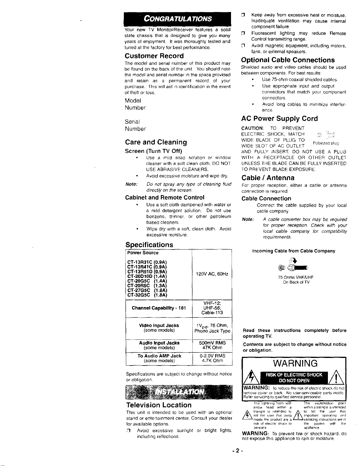
Specifications
Power Source
CT-13R31C (O.gA)
CT-13R41C (0.gA)
CT-13 R51D (0.gA)
CI"-2ODIOD (1.4A)
CT-20GSC (1.4A)
CT-20RSC (t,3A)
CT-27GSC (1,8A)
CT-32GSC (1,8A)
Channel Capability - 181 UHF-56;
120V AC. 60Hz
VHF-12;
Cable-113
[3 Keep away from excessive heat or moisture.
inadequate ventilation may cause internal
component failure.
[1 Fluorescent lighting may reduce Remote
Control transmitting range.
L'l Avoid magnetic equipment, including motors,
fans. or external speakers.
Optional Cable Connections
Shielded audio and video cables should be used
between components. For best results:
Use 75-ohm coaxial shielded cables
Use appropriate input and output
connectors that match your component
connectors.
Avoid long cables to minimize interfer-
ence
AC Power Supply Cord
CAUTION: TO PREVENT
ELECTRIC SHOCK, MATCH _:] "'_-"_
WIDE BLADE OF PLUG TO
WIDE SLOT OF AC OUTLET Polarizedprug
AND FULLY iNSERT. DO NOT USE A PLUG
WITH A RECEPTACLE OR OTHER OUTLET
UNLESS THE BLADE CAN BE FULLY INSERTED
TO PREVENT BLADE EXPOSURE
Cable / Antenna
For proper reception, either a cable or antenna
connection is required.
Cable Connection
Connect the cable supplied by your local
cable company
Note: A cable converter box may be required
for proper reception. Check with your
local cable company for compatibility
requirements.
Incoming Cable from Cable Company
75 Ohms VHF/UHF
On Back of TV
Video Input Jacks t Vp.p,75 Ohm,
(some models) Phono Jack Type
Audio Input Jacks 500mV RMS
(some models) 47K Ohm
To Audio AMP Jack 0-2.0V RMS
(some models) 4.7K Ohm
Specifications are subject to change without notice
or obligation
Television Location
This unit is intended to be used with an optional
stand or entertainment center. Consult your dealer
for available options
:'3 Avoid excesswe sunlight or bright lights,
including reflections.
Read these instructions completely before
operating TV.
Contents are subject to change without notice
or obligation.
WARNING
NARNING: TOreducethe risk of electricshockdo no1
emove coveror back NOuser-serviceableparts inside
%fer servicing toqualifiedsewice personnel
The lightning flash with The exclamation point
arrow head within a within a Iriangie is irltended
triangle =s intended to //_ to tel/ the user lhal
IeII the usel that parts important operating and
'_inside the product are a _se_icing inslructions are in
risk of electric Shock 1o tile papers will the
persons appliance
WARNING: To prevent fire or shock hazard, do
not expose this appliance to rain or moisture
-2-
Antenna Connection
For proper reception of VHF/UHF
channels, an external antenna is required.
For best reception an outdoor antenna
is recommended.
Antenna Mode must be set to TV,
Incoming Cable from Home Antenna
VHF/UHF Antenna
A VHF/UHP indoor antenna and transformer are
supplied with _. Attach to the TV and
adjust the antenna until the picture is clear. (See
Antenna Connection)
Helpful Hints: Cable Preset l
Cable Mode is preset at the factory Antenna users mustchange toAntennaMode in the SETUP Menu I
n
i,
o_
]
.J
Optional Equipment
Connections
Procedure
1 Connect equipment as shown, to front or
rear Audio/Video input jacks
Note: Front and rear Audio/Video
connections cannot be
operated at the same time.
2. Select the Video mode by pressing TV/
VIDEO button,
3. Operate optionar equipment as instructed
_nequipment manual
Note: VCRs, video dtsc players, vtdeo game
equipment, and DSS equipment can also
be connected to the antenna input
connection (See your equipment
manu_i)
Terminals on back of TV (some models)
L TO AUDIOt AMP
O • _ INPUT
R AUDIO- L VIDEO
(Cables notsupplied) .._ voeoOUT
,= = _,uolo ou_. *
To Audio Amplifier (AMP, some
models)
To listen to sound through your stereo syslem
connect it to the input (To Audio AMP) on your TV
Note: TO AUDIO AMP terminals cannot be
used directly for external speakers
Audio Adjustments
1 Press TV SPEAKERS ON button located
on back of set.
Note: If your TV does not have a TV
SPEAKERS ON/OFF button _
select TV SPEAKERS ON
from AUDIO menu
2 Set amplifier volume to minimum. •
3 Adjust TV volume to desired level.
4. Adjust amplifier volume to match the 1-V ._
5 Press TV SPEAKERS OFF button,
located on the ba_k of the set
Note: If your TV does not have a TV
SPEAKERS ON/OFF button,
select OFF& VAO from A UD!O
menu.
6 Volume and mute are new selected
using the TV controls.
VCR or VideoDisc
"o
m
£
0
_0
I-"
STEREO MODELS
Jack usedfor
118"earphone lug
(some rnode_s)
VIDEO L -AUDIO- R
',_ __ J
O O"
VIDEO L -AUDIO- R
dooo o)
t
Terminalsonback of VCR
Terminals on front of TV (some models)
VIDEO AUOIO
Jackused for
1/8" earphone lug
(some mode_s)
-3-
,I
 Loading...