

ORDER NO. MTNC000582A1
B1
Service Manual
Color Television
mplif
i
S
i
e
d
Simplified Manual
NA6LV
Panasonic
Models
CT-2005SB PP326
Chassis
This Simplified Service Manual is issued to add listed models to the Main Service Manual order No. MTNC000101C1.
A full set of schematics, disassembly procedures, and a complete parts list are included in this Simplified Manual.
Please file and use this Simplified Service Manual together with Main Service Manual, order No. MTNC000101C1.
“WARNING! This Service Man ual is desig ned for expe rienced repa ir technici ans only and is not designed f or use by t he general p ublic.
It does not contain warnings or cautions to advise non-technical individuals of potential dangers in attempting to service a product.
Products powered by electricity should be serviced or repaired only by experien ced profess ional techn icians. Any attempt to
service or repair the product or products dealt with in this Service Manual by anyone else could result in serious injury or death.”
The service technician is required to read and follow the “Safety Precautions” and “Important Safety Notice” in the Main Manual.
Copyright 2000 by Matsushita Electric Corporation of
America. All rights reserved. Unauthorized copying
®
and distribution is a violation of law.
Important Safety Notice
Special components are used in this television set which are important for safety. These parts are identified on the
schematic diag ram by the s ymbol and printed in BOLD TYPE o n the replac ement part l ist. It is es senti al that
these critical parts are replaced with the manufacturer’s specified replacement part to prevent X-ray radiation,
shock, fire or other hazards. Do not modify the original design without the manufacturer’s permission.
Safety Precautions
General Guidelines
An Isolation Transformer should always be used
during the servicing of a r eceiver whose c hassis is not
isolated from AC power line. Use a transformer of
adequate power rating as this protects the technician
from accidents resulting in personal injury from
electrical shocks. It will also protec t the Receiver from
being damaged by accidenta l shorting that may occur
during servicing.
When servicing, observe the original lead dress,
especially in the high voltage circuit. Replace all
damaged parts (also parts that show signs of
overheating.)
Always Replace Protective Devices, such as
fishpaper, isolation resistors and capacitors, and
shields after servicing the Receiver. Use only
manufacturer ’s recommended rating for fuses, c ircuits
breakers, etc.
High potentials are present when this Receiver is
operating. Operation of the Receiver without the rear
cover introduces danger for elect rical shock. S ervicing
should not be performed by anyone who is not
thoroughly familiar with the necessary precautions
when servicing high-voltage equipment.
Extreme care should be practiced when Handling the
Picture T ube. Rough handling may cause it to implode
due to atmospheric pres sure. (14.7 lbs per sq. in.). D o
not nick or scratch the glass or subject it to any undu e
pressure. When handling, use safety goggles and
heavy gloves for protection. Discharge the picture
tube by shorting the anode to chassis ground (not to
the cabinet or to other mounting hardware). When
discharging con nec t co ld ground (i.e. dag ground lead)
to the anode with a well insulated wire or use a
grounding probe.
Avoid prolonged exposure at close range to unshielded
areas of the picture tube to prevent exposure to
X-ray radiation.
The Test Picture Tube used for servicin g the chassis
at the bench should incorporate safety glass and
magnetic shieldi ng. The safety glass pro vide shielding
for the tube viewing area against X-ray radiation as
well as implosion. The magnetic sh ield limits the X-ray
radiation around the bell of the pict ure tube in addition
to the restricting magnetic effects. When using a
picture tube test jig for service, ensure that the jig is
capable of handling 33.96kV without causing
X-ray radiation.
Before returning a serviced rec eiver to the owner,
the service technic ian must thoroughly test the unit to
ensure that is completely safe to operate. Do not use a
line isolation transformer when testing.
Leakage Current Cold Check
Unplug the AC cord and connect a jumper between the
two plug prongs.
Measure the resistance between the jumpered AC plug
and expose metallic parts such as screwheads,
antenna terminals, control shafts, etc. If the exposed
metallic part has a return path to the chassis, the
reading should be between 240kΩ and 5.2MΩ. If the
exposed metallic part does not have a return path to
the chassis, the reading should be infinite.
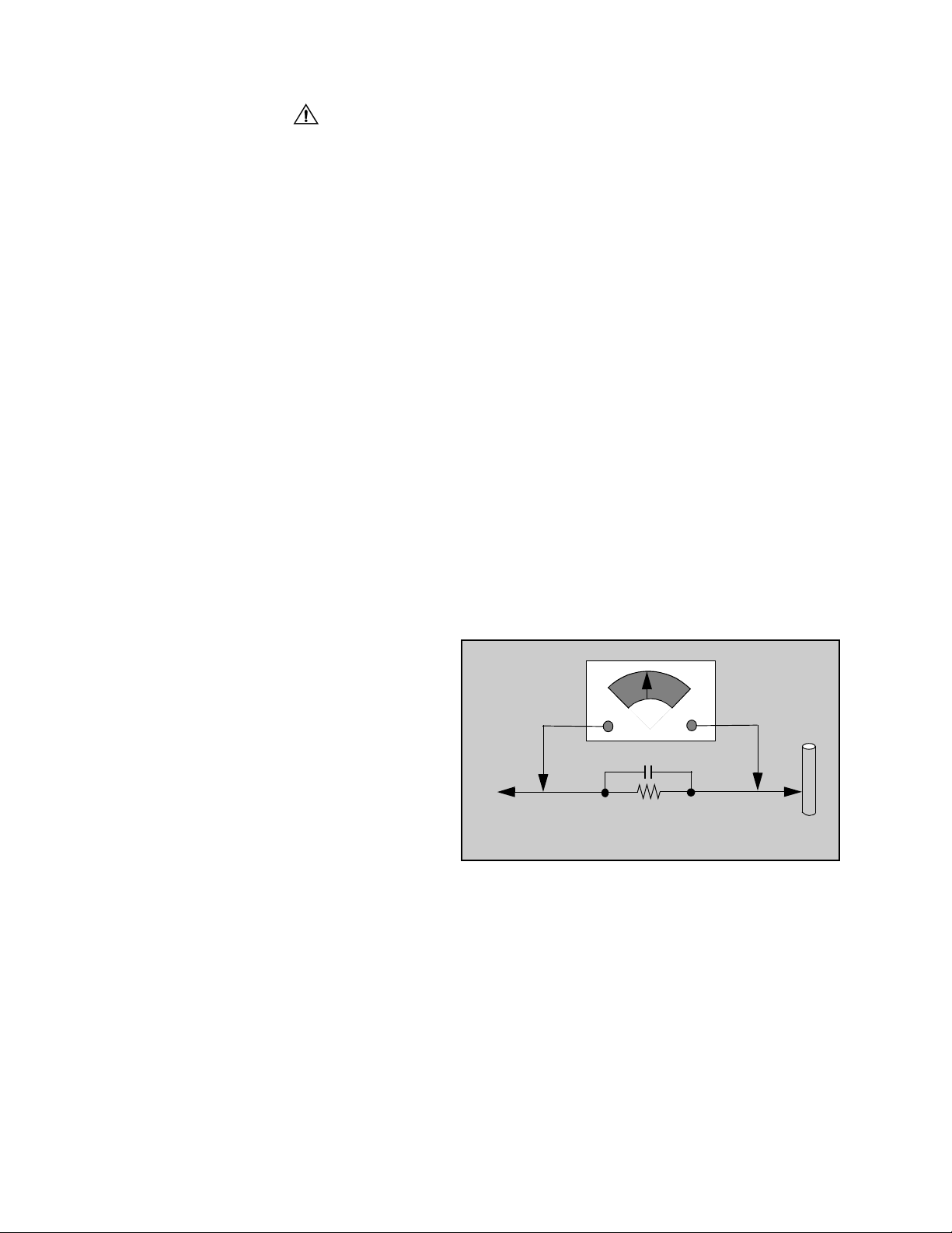
Leakage Current Hot Check (Fig. 1)
Plug the AC cord directly into the AC outlet. Do not use
an isolation transformer during the check.
Connect a 1.5kΩ 10 watt resistor in parallel with a
0.15µF capacitor between an exposed metallic part
and ground. Use earth ground, for example a
water pipe.
Using a DVM with a 1000 ohms/volt sensitivity or
higher, measure the AC potential across the resistor.
Repeat the procedure and measure the voltage
present with all other exposed metallic parts.
Verify that any potential does not exceed 0.75 volt
RMS. A leakage curr ent tes ter (suc h a S impson M odel
229, Sencore Model P R57 or equiv alent) may be used
in the above procedure, in which case any current
measure must not exceed 1/2 milliamp. If any
measurement is out of the specified limits, there is a
possibility of a s hock haz ar d and th e R ece iv er m us t b e
repaired and rechecked before it is returned to the
customer.
AC VOLTMETER
COLD
WATER
PIPE
(GROUND)
0.15µF
TO INSTRUMENT’S
EXPOSED METAL
PARTS
1500Ω,10 W
Figure 1. Hot Check Circuit
X-ray Radiation
WARNING: The potential source of X-ray radiation in the
TV set is in the H igh Voltage section and th e p ict ure tu be.
Note: It is important to use an accurate, calibrated
high voltage meter.
Set the brightness, picture, sharpness and color
controls to Minimum.
Measure the High Voltage. The high voltage shou ld be
27.7kV ± 1.25kV. If the upper limit is out of tolerance,
immediate servic e and correction is requ ired to insure
safe operation and to prevent the possibility of
premature component failu re.
Horizontal Oscillator Disa ble Circuit Test
This test must be performed as a final check before the
Receiver is returned to the customer. See Horizontal
Oscillator Disable Circuit Procedure Check in
this manual.
- 2 -
Important Safety Notice. . . . . . . . . . . . . . . . . . . 2
Safety Precautions . . . . . . . . . . . . . . . . . 2
Service Notes . . . . . . . . . . . . . . . . . . . . . . . . . . . 4
Horizontal Oscillator Disable Circuit . . . . 5
Receivers Feature Table . . . . . . . . . . . . . . . . . . 6
Location of Controls (Receiver)
Receiver Front Control Panel . . . . . . . . . 7
Location of Controls (Remote)
EUR501450. . . . . . . . . . . . . . . . . . . . . . . 8
Component Identification . . . . . . . . . . . . . . . . . 9
Parts List. . . . . . . . . . . . . . . . . . . . . . . . . . . . . . 11
- 3 -
Service Notes
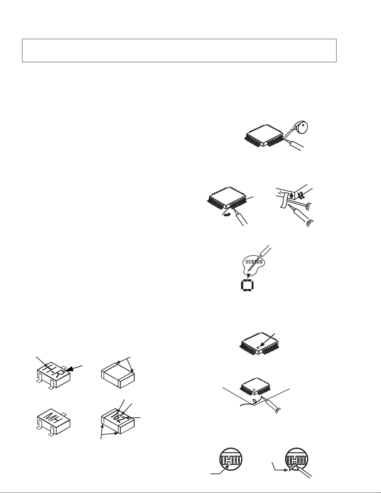
Chip Components
TRANSISTOR
CAPACITOR
RESISTOR
MH DIODE
SOLDER
CAPS
SOLDER
CAPS
1ST DIGIT
2ND DIGIT
MULTIPLIER
=1600 = 1.6k
GRADE
TYPE
COMMON
ANODES
CATHODE
Note: These components are affixed with glue. Be careful not to break or damage any foil under the
component or at the pins of the ICs when removing. Usually applying heat to the component for a
short time while twisting with tweezers will break the component loose.
Leadless Chip Component
(surface mount)
Chip components must be replaced with identical chips
due to critical foil tr ack spacing. There are no ho les in
the board to mount standard transistors or diodes.
Some chips capacitor or resistor board solder pads
may have holes thr ough the board, however the hole
diameter limits standard resistor replacement to 1/8
watt. Standard capacitor may also be limited for the
same reason. It is recommended that identical
components be used.
Chip resistor have a three digit numerical resistance
code - 1st and 2nd significant digits and a multiplier.
Example: 162 = 1600 or 1.6kΩ resistor, 0 = 0Ω (jumper).
Chip capacitors generally do not have the value
indicated on the capacitor. The color of the compo nent
indicates the general range of th e capacitance.
Chip transistors are id enti fied by a two letter code. The
first letter indicates the type and the second l etter, the
grade of transistor.
Chip diodes have a two lette r i den tif ic ati on code as per
the code chart an d are a dual diode pack with either
common anode or common cathode. Check the parts
list for correct diode number.
Component Removal
1. Use solder wick to remove s older fr om compo nent
end caps or terminal.
2. Without pulling up, carefully twist the component
with tweezers to break the adhesive.
3. Do not reuse removed leadless or chip
components since they are subject to stress
fracture during removal.
Chip Component Installation
1. Put a small amount of solder on the board
soldering pads.
2. Hold the chip component against the soldering
pads with tweezers or with a miniature alligator clip
and apply heat to the pad area with a 30 watt iron
until solder flows. Do not appl y heat for more than
3 sec onds.
How to Replace Flat-IC
- Required Tools -
• Soldering iron • De-solder braids
• Iron wire or small awl • Magni fier
1. Remove the solder from all of the pins of a Fla t-IC
by using a de-solder braid.
De-Solder
Flat-IC
2. Put the iron wire under the pins of the Flat-IC an d
pull it in the direction indicated while heating the
pins using a soldering iron. A small awl can be
used instead of the iron wire.
Iron
Wire
Pull
Soldering
Iron
Soldering
Iron
3. Remove the solder from all the pads of the Flat- IC
by using a de-solder braid.
Soldering
Iron
De-Solder
Braid
Flat IC
4. Position the new Flat-IC in pl ace (apply the pins of
the Flat-IC to the soldering pads where the pins
need to be soldered). Properly determine the
positions of the soldering pads and pins by
correctly aligning the polarity symbol.
Polarity Symbol
Braid
Awl
b
e
c
123.....
5. Solder all pins to the soldering pads using a fine
tipped soldering iron.
Solder
Soldering
Iron
6. Check with a magnifier fo r solder bridge between
the pins or for d r y jo int b e twe en pi ns a nd s old er in g
pads. To rem ove a solder bridge, use a de-solder
braid as shown in the figure below.
De-Solder
Braid
Solder
Bridge
Soldering
Iron
- 4 -

Service Notes (Continued)
IMPORTANT: To protect against possible damage to
the solid state devices due to arcing or static
discharge, make cer tain that all g round wir es and CTR
DAG wire are securely connected.
CAUTION: The power supply circuit is above earth
ground and the chassis cannot be polarized. Use an
isolation transformer when servicing the Receiver to
avoid damage to the test equipmen t or to the chassis.
Connect the test equipment to the proper ground ( ) or
( ) when servicing, or incorrect voltages will be
measured.
WARNING: This Receiver has been designed to mee t
or exceed applicable safety and X-ray radiation
protection as specified by government agencies and
independent testing laboratories.
To maintain original product safety design standards
relative to X-ray radiation and shock and fire hazard,
parts indicated with the s ymbol on the schematic
must be replaced with identical parts. Order parts from
the manufacturer’s parts center using the parts
numbers shown in t his service manual, or provide the
chassis number and the part reference number.
For optimum performanc e and reli ability, all other parts
should be replaced with components of
identical specification.
Procedure:
1. Tune in a station to verify that the horizontal is
in sync.
2. Obtain a Monoscope pattern or a signal generator
crosshatch pattern
3. Connect the voltmete r (-) lead to TP D2 and th e (+)
lead to TPD1 (junction of D555 anode, R556 &
R557). Set Bright level to (0 ) a nd Picture for a 1.8
volt reading on the voltmeter.
4. Turn the Receiver OFF. Connect a jumper across
IC803 pin 3 and pin 4. Apply +9V DC to cathode of
D001.
5. Reduce the AC supply voltage to approximately
45V. Connect the high voltage meter to the CRT
anode. (H.V. button).
Note: Use the Dag Ground (C10 on the CRT Board)
to connect the (-) lead of the meter.
6. Turn the Receiver ON. Slowly increase the AC
supply voltage and verify that the high voltages
does not exceed 34.0kV when horizontal just
begins to pull ou t of sync . If the hig h voltage is not
within the specified limit, the cause must be
determined and corrected before the Receiver is
returned to the costumer.
Horizontal Oscillator Disable Circuit
This chassis employs a special circuit to protect
against excessive high voltage and beam current. If, for
any reason, the high voltage and b eam c ur rent exceed
a predetermined level this protective circuit activates
and detunes the horizontal oscillator that limits the high
voltage. The over-voltage protection circuit is not
adjustable. However, if components indicated by the
symbol on the schematic in either the horizontal
sweep system or the over-voltage protection circuit
itself are changed, the operation of the circuit should
be checked using the following procedure:
Equipment needed to check the disabled circuit:
1. Voltmeter (0 - 200V scale)
2. High Voltage Meter (0- 50kV)
3. Variac or Isolati on Transformer
- 5 -
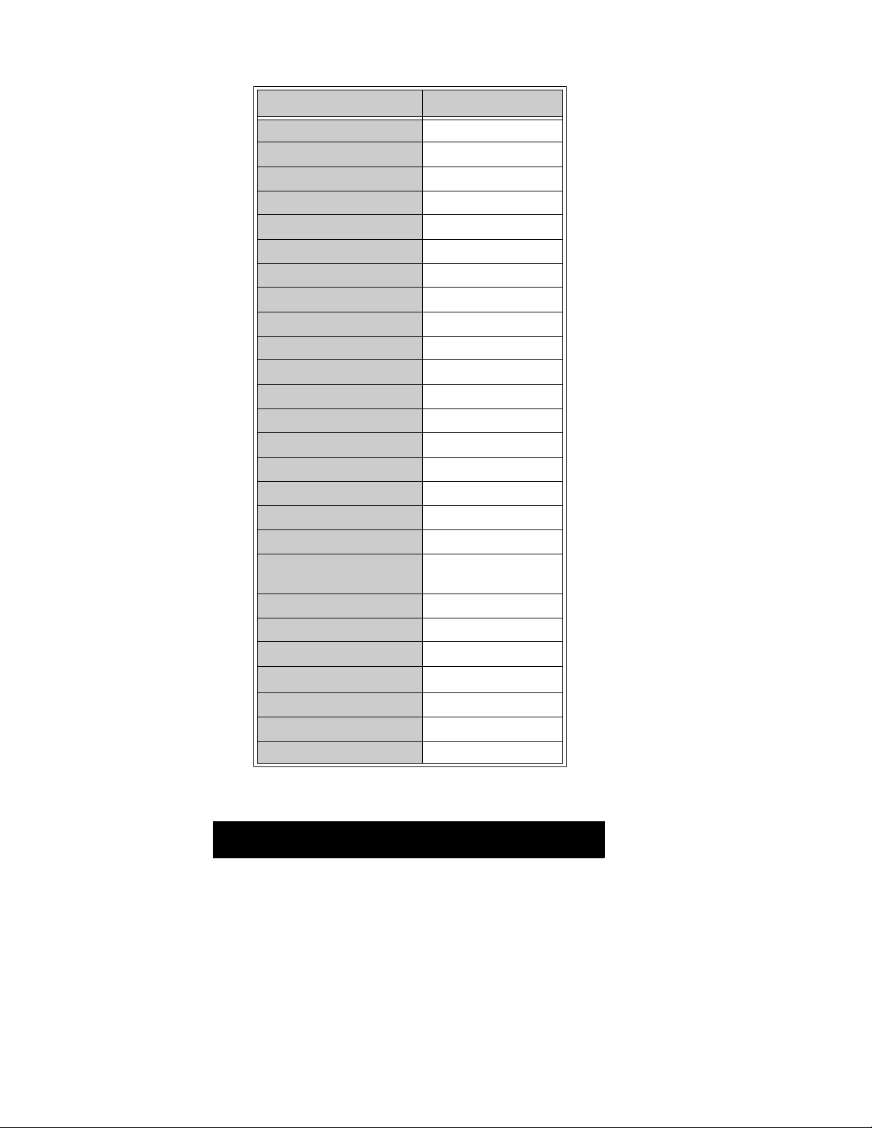
Receiver Feature Table
FEATURE\MODEL CT-2005SB
Chassis NA6LV
Tunning system 40K
# of channels 181
Menu language Eng/Span/Fr
Closed Caption X
V-Chip X
75 Ω input X
Remote Model # EUR501450
Picture tube A51KQN011X
Notch filter P
V/A norm (X=both) V
MTS/SAP/DBX X
AI Sound (DXL:*,SMPL:X) X
Built-in audio power 1.5Wx2 (10%)
# of speakers 2
Audio out(FAO:F,VAO:V) V
A/V in (rear/front) 1/1
HPJ/HPJ/MISC HPJ
Dimensions mm
(WxDxH) in
Weight (kg/lbs) 20.09/44.28
Power source (V/Hz) 120/60
Anode voltage 27.7kV ± 1.25kV
Video input jack
Audio input jack 500mV RMS 47kΩ
A-Board TNP2AH018 CB
C-Board TNP2AA062 AA
516x492x462
20.28x19.33x18.15
75Ω, phon o jack
1V
p-p
Table 1. Receiver Features
Specifications are subject to change without notice or obligation.
Dimensions and weights are approximate.
- 6 -
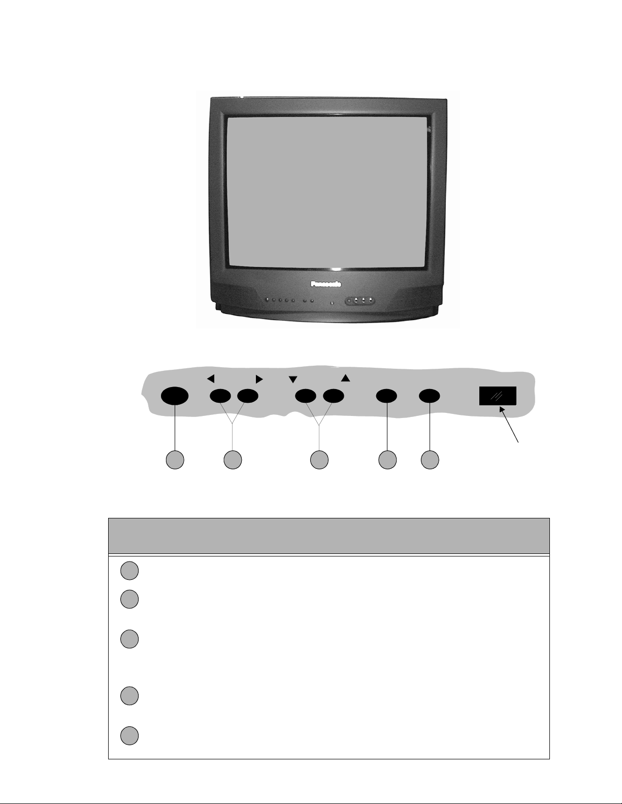
Location of Controls (Receiver)
Figure 2. Location of Controls (Typical receiver).
POWER VOLUME CHANNEL ACTION TV/VIDEO
1 2 4 53
Quick Reference Control Operation
Quick Reference
Control Operation
Power Button - Press to turn ON or OFF.
1
Volume Buttons - Press to adjust Sound Level, or to adjust Audio Menus, Video
2
Menus, and select operating features when menus are displayed
Channel Buttons - Press to sele ct programme d channels. Pre ss to highlight d esired
3
features when menus are dis play ed. Also us e to selec t Cable Conv erte r box chan nels
after programming Remo te Control Infra-red codes ( the TV/AUX/CABLE switc h must
be set in CABLE position).
Remote Control
Sensor
Action Button - Press to display Main Menu and access On Screen feature and
4
Adjustment Menus.
TV/Video Button - Press to select TV or one of two Video Inputs, for the Main Pict ure
5
or the PIP frame (when PIP frame is displayed).
- 7 -
 Loading...