

Panasonic CT-13R17B, CT-13R27W, CT-13R37S Service Manual

ORDER NO. MTNC020409C1
B1
Service Manual
Color Television
Main Manual
Panasonic
Models
CT-13R17B
CT-13R27W
CT-13R37S
This service manual is issued as a service guide for the models listed above.
Included in this manual are a set of schematic, block diagrams, functional descriptions, alignment procedures,
disassembly procedures and a complete parts list.
Chassis
TMB535
TMB535
TMB535
“WARNING! This Service Manual is designed for experienced repair technicians only and is not designed for use by the general public.
It does not contain warnings or cautions to advise non-technical individuals of potential dangers in attempting to service a product.
Products powered by electricity should be serviced or repaired only by experienced professional technicians. Any attempt to
service or repair the product or products dealt with in this Service Manual by anyone else could result in serious injury or death.”
The service technician is required to read and follow the “Safety Precautions” and “Important Safety Notice” in this Main Manual.
Copyright 2002 by Matsushita Electric Corporation of
America. All rights reserved. Unauthorized copying
and distribution is a violation of law.

CONTENTS
CONTENTS .................................................................................................................................................
Important Safety Notice ............................................................................................................................
Service Notes .............................................................................................................................................
GENERAL SPECIFICATIONS....................................................................................................................
DISASSEMBLY INSTRUCTIONS
1. REMOVAL OF ANODE CAP ............................................................................................................
2. NOTE FOR THE REMOVAL OF THE MAIN PCB............................................................................
SERVICE MODE LIST ................................................................................................................................
CONFIRMATION OF HOURS USED .........................................................................................................
WHEN REPLACING EEPROM (MEMORY) IC ..........................................................................................
ELECTRICAL ADJUSTMENTS
1. BEFORE MAKING ELECTRICAL ADJUSTMENTS .........................................................................
2. BASIC ADJUSTMENTS ....................................................................................................................
3. PURITY AND CONVERGENCE ADJUSTMENTS ...........................................................................
4. ELECTRICAL ADJUSTMENT PARTS LOCATION GUIDE (WIRING CONNECTION)...................
BLOCK DIAGRAM......................................................................................................................................
PRINTED CIRCUIT BOARDS
MAIN/CRT ..............................................................................................................................................
SCHEMATIC DIAGRAMS
MICON/TUNER ......................................................................................................................................
CHROMA................................................................................................................................................
TV POWER.............................................................................................................................................
DEFLECTION/CRT ................................................................................................................................
SOUND/AV .............................................................................................................................................
VOLTAGE LIST ..........................................................................................................................................
WAVEFORMS .............................................................................................................................................
MECHANICAL EXPLODED VIEW .............................................................................................................
MECHANICAL REPLACEMENT PARTS LIST .........................................................................................
ELECTRICAL REPLACEMENT PARTS LIST...........................................................................................
A1-1
A2-1
A2-2, A2-3
A3-1~A3-3
B-1
B-1
C-1
C-1
C-1
D-1
D-1, D-2
D-3
D-4
E-1, E-2
F-1~F-4
G-1, G-2
G-3, G-4
G-5, G-6
G-7, G-8
G-9, G-10
H-1
I-1, I-2
J-1
K1-1
K2-1~K2-3
A1-1
Important Safety Notice
Special components are used in this television set which are important for safety. These parts are identified on the
schematic diagram by the symbol and printed in BOLD TYPE on the replacement part list. It is essential that
these critical parts are replaced with the manufacturer's specified replacement part to prevent X-ray radiation, shock,
fire or other hazards. Do not modify the original design without the manufacturer's permission.
Safety Precautions
General Guidelines
An Isolation Transformer should always be used
during the servicing of a receiver whose chassis is not
isolated from AC power line. Use a transformer of
adequate power rating as this protects the technician
from accidents resulting in personal injury from electrical
shocks. It will also protect the Receiver from being
damaged by accidental shorting that may occur during
servicing.
When servicing, observe the original lead dress,
especially in the high voltage circuit. Replace all
damaged parts (also parts that show signs of
overheating.)
Always Replace Protective Devices, such as
fishpaper, isolation resistors and capacitors, and shields
after servicing the Receiver. Use only manufacturer's
recommended rating for fuses, circuits breakers, etc.
High potentials are present when this Receiver is
operating. Operation of the Receiver without the rear
cover introduces danger for electrical shock. Servicing
should not be performed by anyone who is not
thoroughly familiar with the necessary precautions when
servicing high-voltage equipment.
Extreme care should be practiced when Handling the
Picture Tube. Rough handling may cause it to implode
due to atmospheric pressure. (14.7 lbs per sq. in.). Do
not nick or scratch the glass or subject it to any undue
pressure. When handling, use safety goggles and heavy
gloves for protection. Discharge the picture tube by
shorting the anode to chassis ground (not to the cabinet
or to other mounting hardware). When discharging
connect cold ground (i.e. dag ground lead) to the anode
with a well insulated wire or use a grounding probe.
Avoid prolonged exposure at close range to unshielded
areas of the picture tube to prevent exposure to X-ray
radiation.
The Test Picture Tube used for servicing the chassis at
the bench should incorporate safety glass and magnetic
shielding. The safety glass provide shielding for the tube
viewing area against X-ray radiation as well as
implosion. The magnetic shield limits the X-ray radiation
around the bell of the picture tube in addition to the
restricting magnetic effects. When using a picture tube
test jig for service, ensure that the jig is capable of
handling 50kV without causing X-ray radiation.
Before returning a serviced receiver to the owner,
the service technician must thoroughly test the unit to
ensure that is completely safe to operate. Do not use a
line isolation transformer when testing.
Leakage Current Cold Check
Unplug the AC cord and connect a jumper between the
two plug prongs.
Measure the resistance between the jumpered AC plug
and expose metallic parts such as screwheads, antenna
terminals, control shafts, etc. If the exposed metallic
part has a return path to the chassis, the reading should
be between 240k and 5.2M . If the exposed metallic
part does not have a return path to the chassis, the
reading should be infinite.
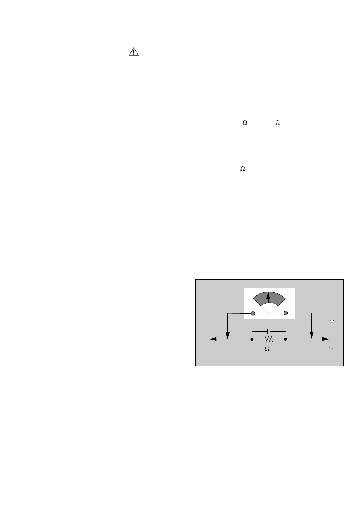
Leakage Current Hot Check (Fig. 1)
Plug the AC cord directly into the AC outlet. Do not use
an isolation transformer during the check.
Connect a 1.5k 10 watt resistor in parallel with a
0.15µF capacitor between an exposed metallic part and
ground. Use earth ground, for example a water pipe.
Using a DVM with a 1000 ohms/volt sensitivity or higher,
measure the AC potential across the resistor.
Repeat the procedure and measure the voltage present
with all other exposed metallic parts.
Verify that any potential does not exceed 0.75 volt RMS.
A leakage current tester (such a Simpson Model 229,
Sencore Model PR57 or equivalent) may be used in the
above procedure, in which case any current measure
must not exceed 0.5 milliamp. If any measurement is out
of the specified limits, there is a possibility of a shock
hazard and the Receiver must be repaired and
rechecked before it is returned to the customer.
AC VOLTMETER
COLD
WATER
PIPE
(GROUND)
0.15µF
TO INSTRUMENT’S
EXPOSED METAL
PARTS
1500 ,10 W
Figure 1.
Hot Check Circuit
X-ray Radiation
WARNING: The potential source of X-ray radiation in
the TV set is in the High Voltage section and the picture
Note:
Set the brightness and picture controls to Minimum.
Measure the High Voltage. The high voltage should be
24.5 ± 1.0kV. If the upper limit is out of tolerance,
immediate service and correction is required to insure
safe operation and to prevent the possibility of
premature component failure.
It is important to use an accurate, calibrated high
voltage meter.
A2-1
Service Notes
These components are affixed with glue. Be careful not to break or damage any foil under the
Note:
component or at the pins of the ICs when removing. Usually applying heat to the component for a
short time while twisting with tweezers will break the component loose.
Leadless Chip Component
(surface mount)
Chip components must be replaced with identical chips
due to critical foil track spacing. There are no holes in
the board to mount standard transistors or diodes. Some
chips capacitor or resistor board solder pads may have
holes through the board, however the hole diameter limits
standard resistor replacement to 1/8 watt. Standard
capacitor may also be limited for the same reason. It is
recommended that identical components be used.
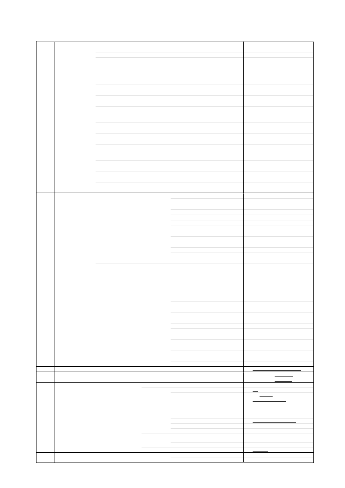
Chip resistor have a three digit numerical resistance code
- 1st and 2nd significant digits and a multiplier.
Example: 162 = 1600 or 1.6k resistor, 0 = 0 (jumper).
Chip capacitors generally do not have the value indicated
on the capacitor. The color of the component indicates the
general range of the capacitance.
Chip transistors are identified by a two letter code. The
first letter indicates the type and the second letter, the
grade of transistor.
Chip diodes have a two letter identification code as per the
code chart and are a dual diode pack with either common
anode or common cathode. Check the parts list for correct
diode number.
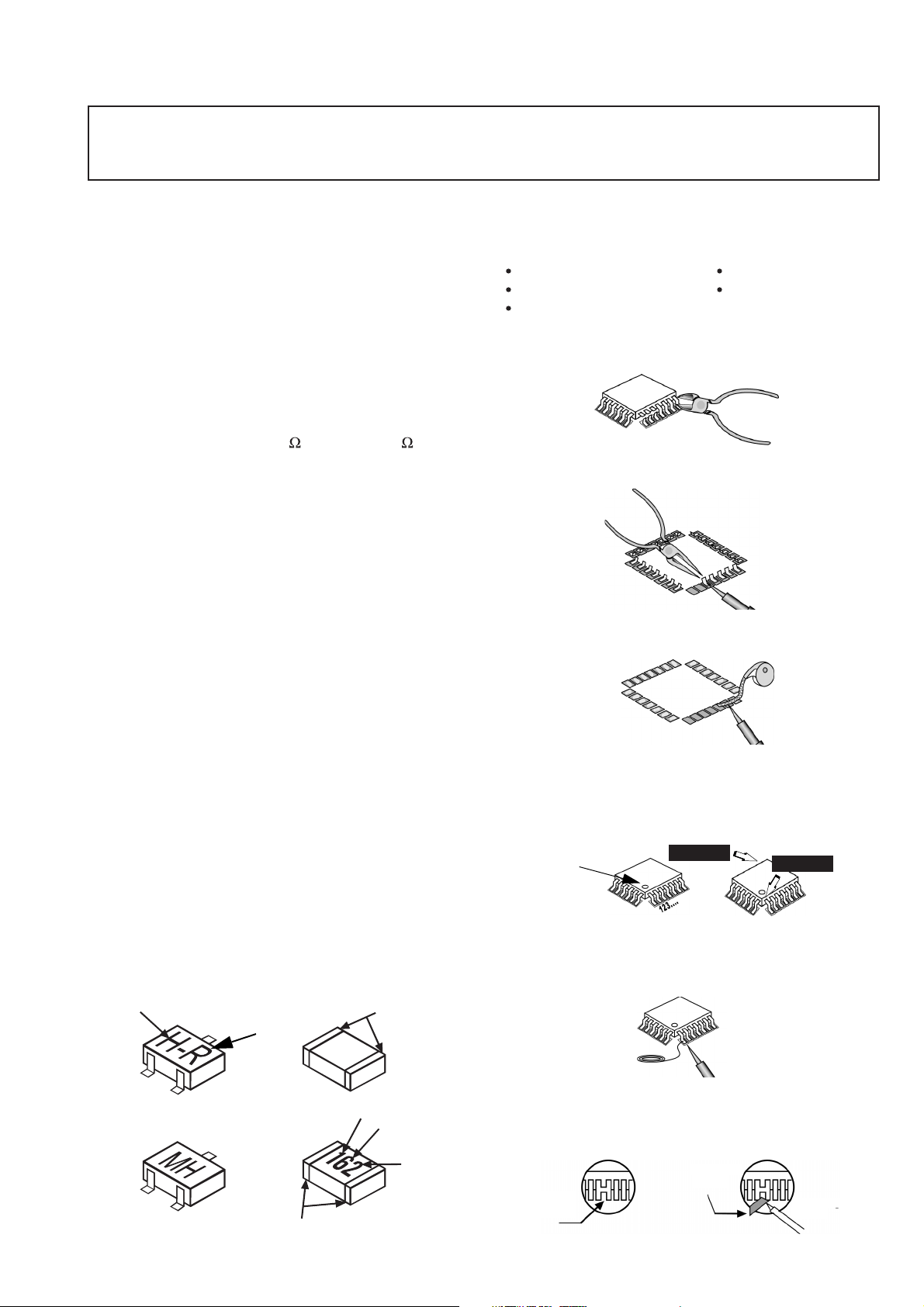
Component Removal
Use solder wick to remove solder from component end
1.
caps or terminal.
Without pulling up, carefully twist the component with
2.
tweezers to break the adhesive.
Do not reuse removed leadless or chip components
3.
since they are subject to stress fracture during
removal.
Chip Component Installation
1.2.Put a small amount of solder on the board soldering
pads.
Hold the chip component against the soldering pads
with tweezers or with a miniature alligator clip and
apply heat to the pad area with a 30 watt iron until
solder flows. Do not apply heat for more than 3
seconds.
Chip Components
TYPE
B
ANODES
E
TRANSISTOR
GRADE
C
COMMON
CATHODE
SOLDER
CAPS
CAPACITOR
1ST DIGIT
RESISTORMH DIODE
SOLDER
CAPS
2ND DIGIT
MULTIPLIER
=1600 = 1.6k
A2-2
How to Replace Flat-IC
- Required Tools -
Soldering iron De-solder braids
Needle nose pliers Magnifier
Wire cutters (sharp & small)
Cut the pins of a defective IC with wire cutters.
1.
Remove IC from board. If IC is glued to the board,
heat the IC and release the IC. See Note above.
Flat IC
Using soldering iron and needle nose pliers remove
2.
the IC pins from the board.
Soldering
Iron
Using de-soldering braid and soldering iron remove
3.
solder from affected are on board (pads).
De-soldering
Braid
Soldering
Iron
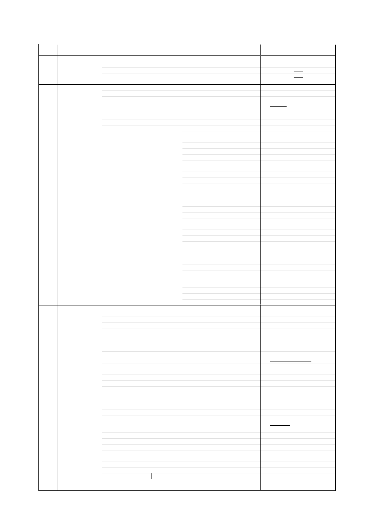
Position the new Flat-IC in place (apply the pins of
4.
the Flat-IC to the soldering pads where the pins
need to be soldered). Determine the positions of
the soldering pads and pins by correctly aligning
the polarity symbol. Solder pin #1 first, align the IC.
Polarity
symbol
Solder the pin opposite to pin #1. This will assist
positioning the IC.
5.
Solder all pins to the soldering pads using a fine
tipped soldering iron.
Solder
Check with a magnifier for solder bridge between
6.
the pins or for dry joint between pins and soldering
pads. To remove a solder bridge, use a de-solder
braid as shown in the figure below.
Solder
Bridge
2nd solder
De-Solder
Braid
1st solder
Soldering
Iron
Soldering
lron

Service Notes (Continued)
IMPORTANT: To protect against possible damage to the
solid state devices due to arcing or static discharge, make
certain that all ground wires and CTR DAG wire are
securely connected.
CAUTION: The power supply circuit is above earth
ground and the chassis cannot be polarized. Use an
isolation transformer when servicing the Receiver to avoid
damage to the test equipment or to the chassis. Connect
the test equipment to the proper ground ( ) or ( ) when
servicing, or incorrect voltages will be measured.
WARNING: This Receiver has been designed to meet
or exceed applicable safety and X-ray radiation
protection as specified by government agencies and
independent testing laboratories.
To maintain original product safety design standards
relative to X-ray radiation and shock and fire hazard,
parts indicated with the symbol on the schematic
must be replaced with identical parts. Order parts from
the manufacturer’s parts center using the parts
numbers shown in this service manual, or provide the
chassis number and the part reference number.
For optimum performance and reliability, all other parts
should be replaced with components of identical
specification.
A2-3

GENERAL SPECIFICATIONS
G-1 TV CRT CRT Size / Visual Size 13 inch / 335.4mmV
G-2 Tuning Broadcasting System US System M
G-3 Power Power Source AC 120V AC 60Hz
G-4 Regulation Safety UL
G-5 Temperature Operation 0oC ~ +40oC
G-6 Operating Humidity Less then 80% RH
G-7 On Screen Menu Yes
System CRT Type Normal
Color System NTSC
Speaker 1Speaker
Sound Output MAX
NTSC3.58+4.43 /PAL60Hz No
System Tuner and System 1Tuner
Receive CH Destination Ohers
Intermediate Picture(FP) 45.75MHz
Frequency Sound(FS) 41.25MHz
Preset CH
Stereo/Dual TV Sound
Tuner Sound Muting Yes
Power Consumption at AC
Protector Power Fuse Yes
Display Menu Type Picture(Matsusita Type)
Picture Yes
Audio No
SET UP Yes
Timer Yes
Lock Yes
Exit Yes
Control Level Yes
Stereo,Audio Output,SAP No
Video(Aux) Yes
Color Stream No
Channel(TV/Cable) Yes
CH Label No
Sound Mute Yes
V-chip Rating Yes
Deflection
Magnetic Field BV/BH +0.45G/0.18G
Position Bottom
Size
Impedance 8 ohm
10%(Typical)
Tuning System F-Synth
Input Impedance VHF/UHF 75 ohm
CH Coverage A - I, J - W, W+1 - W+84
FP-FS 4.50MHz
DC -
Stand by (at AC)
Per Year
Radiation FCC
X-Radiation DHHS
Storage -20oC ~ +60oC
Contrast(Picture) Yes
Brightness Yes
Color Yes
Tint Yes
Sharpness Yes
Normal Yes
Bass No
Treble No
Balance No
BBE On/Off No
Stable Sound On/Off No
Language Yes
Mode Yes
Auto Program Yes
Manual Program Yes
CC Yes
CH Label No
Favorite CH No
Color Stream DVD/DTV No
Sound Yes
Brightness Yes
Contrast(Picture) Yes
Color Yes
Tint (NTSC Only) Yes
Sharpness Yes
Tuning No
Bass No
Treble No
Balance No
Back Light No
90 degree
1.5X2.5 Inch
1.0 W
0.8 W
2 - 69, 4A, A-5 - A-1,
No
No
54 W at AC 120 V 60 Hz
3 W at AC 120 V 60 Hz
-- kWh/Year
A3-1
GENERAL SPECIFICATIONS
G-8 OSD Language English French Spanish
G-9 Clock and Sleep Timer Max Time 120 Min
Timer Step
On/Off Timer Program(On Tim / Off Tim)
Wake Up Timer
Timer Back-up (at Power Off Mode) more than -- Min Sec
G-10 Remote Unit
Control Glow in Dark Remocon No
Format KASEIKYO
Custom Code
Power Source Voltage(D.C) 3V
Total Keys 20 Keys
Keys Power Yes
G-11 Features Auto Degauss Yes
Auto Shut Off Yes
Canal+ No
CATV Yes
Anti-theft No
Rental No
Memory(Last CH) Yes
Memory(Last Volume) Yes
V-Chip Yes
BBE No
Auto Search No
CH Allocation No
SAP No
Just Clock Function No
CH Label No
VM Circuit No
Full OSD No
Premiere No
Comb Filter No
Auto CH Memory Yes
Hotel Lock No
Closed Caption Yes
Stable Sound No
FBT Leak Test Protect Yes
CH Lock No
Video Lock No
Game Timer No
Power On Memory Yes
Energy Star Yes(Buyer's Responsibility)
Favorite CH No
OSD Language Setting English
10 Min
No
No
RC-FF
08-00 h
UM size x pcs UM-3(AA) x 2 pcs
1 Yes
2 Yes
3 Yes
4 Yes
5 Yes
6 Yes
7 Yes
8 Yes
9 Yes
0 Yes
100 No
CH Up(UP) Yes
CH Down(DOWN) Yes
Volume Up(Right) Yes
Volume Down(Left) Yes
TV/Caption/Text No
CH1/CH2 No
TV/Video(TV/AV) Yes
CH RTN/CH ENT(Quick View) Yes
Sleep No
RE Call(Call) Yes
Reset No
Menu No
Enter No
Mute Yes
Action Yes
Exit No
MTS(Audio Select) No
Set + No
Set - No
Type USA,ORION Type
Lines
A3-2
GENERAL SPECIFICATIONS
(
)
(
)
C
dges / 6 Surfaces
G-12 Accessories Owner's Manual Language English/Spanish
Remote Control Unit Yes
Rod Antenna Yes
Loop Antenna
U/V Mixer
DC Car Cord (Center+)
Guarantee Card
Warning Sheet
Circuit Diagram
Antenna Change Plug
Service Facility List
Important Safety Instruction Yes
Dew/AHC Caution Sheet
AC Plug Adapter
Quick Set-up Sheet
Battery Yes
AC Cord
AV Cord (2Pin-1Pin)
Registration Card (NDL Card)
ESP Card
PTB Sheet
300 ohm to 75 ohm Antenna Adapter
G-13 Interface Switch Front Power Yes
Rear AC/DC No
Indicator Power No
Terminals Front Video Input
Rear Video Input(Rear1)
G-14 Set Size Approx. W x D x H (mm)
G-15 Weight Net (Approx.)
G-16 Carton Master Carton
Gift Box Yes
Drop Test
Container Stuffing
G-17 Cabinet Material Cabinet Front PS 94V0 DECABROM
W/ Warranty Yes
Poles 1Poles
Terminal
--
E
No
No
No
No
No
No
No
No
No
No
No
No
No
No
No
No
No
No
No
No
No
No
No
No
No
20.9 lbs
24.4lbs
No
Sets
/--
No
Sets/40' container
Terminal -
UM size x pcs UM3(AA) x 2
OEM Brand Yes
System Select No
Main Power SW No
Sub Power No
CH Up(UP) Yes
CH Down(DOWN) Yes
Volume Up(Right) Yes
Volume Down(Left) Yes
ACTION=Volume Up+Volume Down Yes
TV/CATV Selector No
Degauss No
Main Power SW No
Stand-by No
On Timer No
Audio Input
Other Terminal
Video Input(Rear2)
Audio Input(Rear1)
Audio Input(Rear2)
Video Output
Audio Output
Euro Scart
Color Stream
Diversity No
Ext Speaker No
DC Jack 12V(Center +) No
VHF/UHF Antenna Input
AC Outlet No
Gross (Approx.) 11.0kg
Content
Material
Dimensions W x D x H(mm)
Description of Origin
Material Double/White
Dimensions W x D x H(mm)
Design As per Buyer's
Description of Origin Yes
Height (cm) 62
Cabinet Rear PS 94V0 DECABROM
RCA
RCA x 1
Ear Phone
F Type
359.4 x 354 x 337
9.5 kg
----
-- x -- x --
440 x 408 x 396
Natural Dropping At 1
725
A3-3
orner / 3
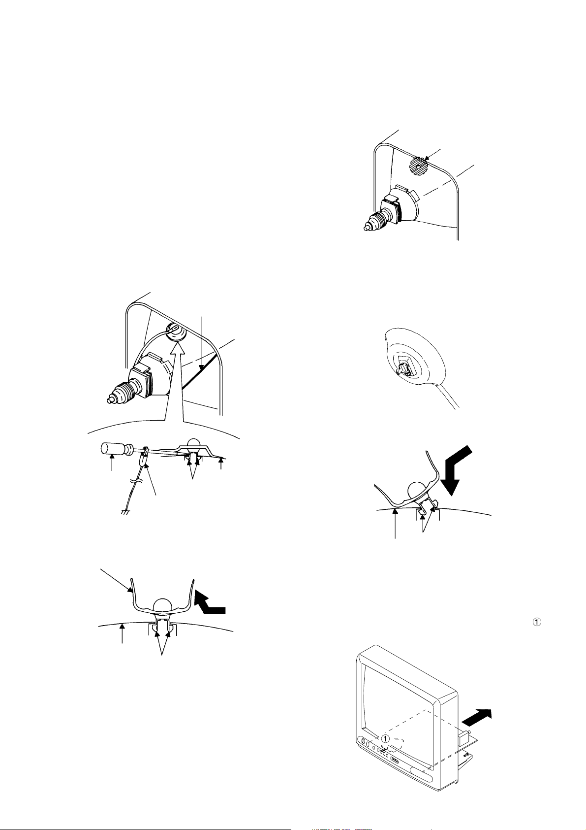
DISASSEMBLY INSTRUCTIONS
1. REMOVAL OF ANODE CAP
Read the following NOTED items before starting work.
*
After turning the power off there might still be a potential
voltage that is very dangerous. When removing the
Anode Cap, make sure to discharge the Anode Cap's
potential voltage.
*
Do not use pliers to loosen or tighten the Anode Cap
terminal, this may cause the spring to be damaged.
REMOVAL
1. Follow the steps as follows to discharge the Anode Cap.
Connect one end of an Alligator Clip to the metal part of a
flat-blade screwdriver and the other end to ground.
While holding the plastic part of the insulated Screwdriver,
touch the support of the Anode with the tip of the
Screwdriver.
A cracking noise will be heard as the voltage is discharged.
GND on the CRT
INSTALLATION
1. Clean the spot where the cap was located with a small
amount of alcohol.
Location of Anode Cap
NOTE
Confirm that there is no dirt, dust, etc. at the spot where
the cap was located.
2.3.Arrange the wire of the Anode Cap and make sure the
wire is not twisted.
Turn over the Rubber Cap.
Screwdriver
Alligator Clip
GND on the CRT
Flip up the sides of the Rubber Cap in the direction of the
2.
arrow and remove one side of the support.
Rubber Cap
CRT
3. After one side is removed, pull in the opposite direction to
remove the other.
NOTE
Take care not to damage the Rubber Cap.
Support
Support
CRT
4. Insert one end of the Anode Support into the anode button,
then the other as shown in the figure below.
Support
CRT
5.6.Confirm that the Support is securely connected.
Put on the Rubber Cap without moving any parts.
2. NOTE FOR THE REMOVAL OF THE
MAIN PCB
When the removal of the Main PCB, remove the hook
first, then draw it in the direction of the arrow.
B-1
SERVICE MODE LIST
This unit provided with the following SERVICE MODES so you can repair, examine and adjust easily.
To enter the Service Mode, press both set key and remote control key for more than 1 second.
Set Key
VOL. (-) MIN 0
Remocon Key
Operations
Releasing of V-CHIP PASSWORD.
User Reset.
VOL. (-) MIN 1
NOTE: If you set a factory initialization, the memories are reset such as the
channel setting, and the POWER ON total hours.
Remocon code selection.
VOL. (-) MIN 3
NOTE:
If you perform the remocon code selection, the remocon cannot be used.
So, do not select the remocon code for the normal servicing.
POWER ON total hours is displayed on the screen.
Refer to the "CONFIRMATION OF HOURS USED".
VOL. (-) MIN
6
Can be checked of the INITIAL DATA of MEMORY IC.
Refer to the "WHEN REPLACING EEPROM (MEMORY) IC".
VOL. (-) MIN
9
Display of the Adjustment MENU on the screen.
Refer to the "ELECTRICAL ADJUSTMENT" (On-Screen Display Adjustment).
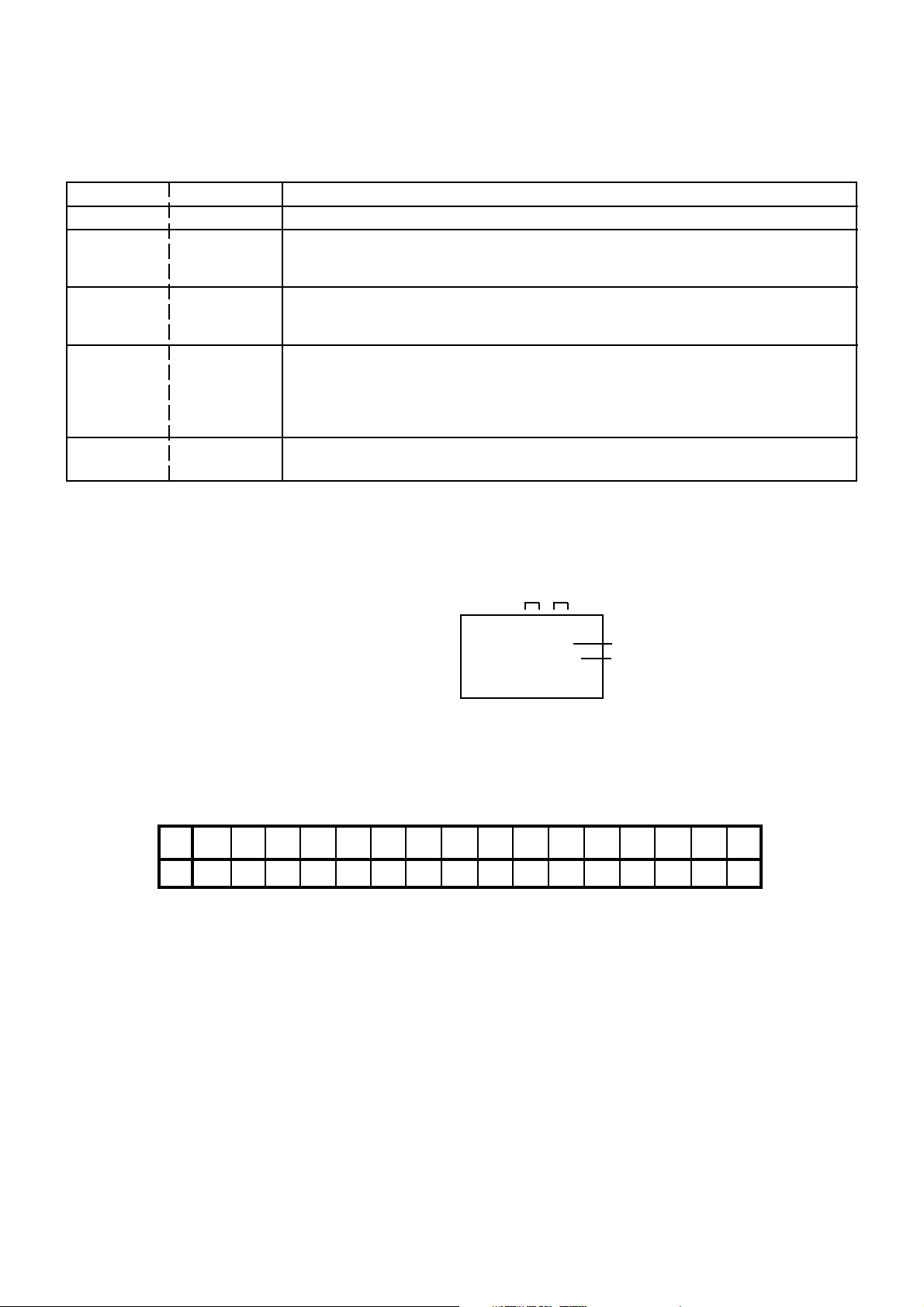
CONFIRMATION OF HOURS USED
POWER ON total hours can be checked on the screen. Total hours are displayed in 16 system of notation.
NOTE: If you set a factory initialization, the total hours is reset to "0".
1.
Set the VOLUME to minimum.
2.
Press both VOL. DOWN button on the set and Channel
button (6) on the remote control for more than 1 second.
3.
After the confirmation of using hours, turn off the power.
ADDRESS DATA
INIT 00 08
CRT ON 0010
FIG. 1
Initial setting content of MEMORY IC.
POWER ON total hours.
= (16 x 16 x 16 x thousands digit value)
+ (16 x 16 x hundreds digit value)
+ (16 x tens digit value)
+ (ones digit value)
WHEN REPLACING EEPROM (MEMORY) IC
If a service repair is undertaken where it has been required to change the MEMORY IC, the following steps should be taken to
ensure correct data settings while making reference to TABLE 1.
+2INI +0 +1 +3 +4
00
1B
24 09 09 0A
BD
Table 1
1.
Enter DATA SET mode by setting VOLUME to minimum.
2.
Press both VOL. DOWN button on the set and Channel button (6) on the remote control for more than 1 second.
ADDRESS and DATA should appear as FIG 1.
3.
ADDRESS is now selected and should "blink". Using the CH. UP/DOWN button on the remote, step through the
ADDRESS until required ADDRESS to be changed is reached.
4.
Press VOL. UP/DOWN button to select DATA. When DATA is selected, it will "blink".
5.
Again, step through the DATA using VOL. UP/DOWN button until required DATA value has been selected.
6.
Pressing CH. UP/DOWN button will take you back to ADDRESS for further selection if necessary.
7.
Repeat steps 3 to 6 until all data has been checked.
8.
When satisfied correct DATA has been entered, turn POWER off (return to STANDBY MODE) to finish DATA input.
The unit will now have the correct DATA for the new MEMORY IC.
+A
+9+5 +6 +7 +8
4408 60 98 13
00 D5 FF A5
25
+F+B +C +D +E
C-1
 Loading...