

Panasonic CS-V18DKE, CS-V24DKE, CU-V18DKE, CU-V24DKE Service Manual
Order No. MAC0410044C2
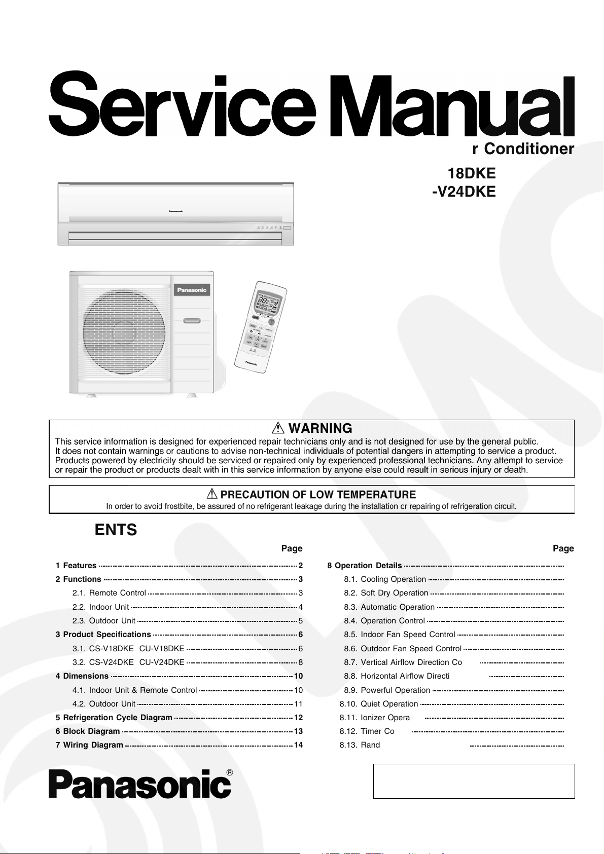
Air Conditioner
CS-V18DKE CU-V18DKE
CS-V24DKE CU-V24DKE
CONTENTS
Page Page
1 Features 2
2 Functions
2.1. Remote Control
2.2. Indoor Unit
2.3. Outdoor Unit
3 Product Specifications
3.1. CS-V18DKE CU-V18DKE
3.2. CS-V24DKE CU-V24DKE
4 Dimensions
4.1. Indoor Unit & Remote Control
4.2. Outdoor Unit
5 Refrigeration Cycle Diagram
6 Block Diagram
7 Wiring Diagram
8 Operation Details 16
3
3
4
5
6
6
8
10
10
11
12
13
14
8.1. Cooling Operation
8.2. Soft Dry Operation
8.3. Automatic Operation
8.4. Operation Control
8.5. Indoor Fan Speed Control
8.6. Outdoor Fan Speed Control
8.7. Vertical Airflow Direction Control
8.8. Horizontal Airflow Direction Control
8.9. Powerful Operation
8.10. Quiet Operation
8.11. Ionizer Operation
8.12. Timer Control
8.13. Random Auto Restart Control
© 2004 Panasonic HA Air-Conditioning (M) Sdn Bhd
(11969-T). All rights reserved. Unauthorized copying
and distribution is a violation of law.
16
17
18
18
20
22
22
23
24
24
25
26
27
CS-V18DKE CU-V18DKE / CS-V24DKE CU- V24DKE
8.14. Remote Control Signal Receiving Sound 27
9 Operating Instructions
10 Installation Instructions
10.1. Safety Precautions
10.2. Indoor Unit
10.3. Outdoor Unit
11 Installation And Servicing Air Conditioner Using R410A
11.1. Outline
11.2. Tools For Installing/Servicing Refrigerant Piping
11.3. Refrigerant Piping Work
11.4. Installation, Transferring, Servicing
12 Servicing Information
12.1. Distinction Of Lead Free (PbF) Printed Circuit Board
12.2. Indoor Electronic Controllers Removal Procedures
12.3. Cross Flow Fan and Indoor Fan Motor Removal
Procedures
12.4. Remote Control Reset
12.5. Auto OFF/ON Button
13 Troubleshooting Guide
13.1. Refrigeration Cycle System
13.2. Relationship Between The Condition Of The Air
Conditioner And Pressure And Electric Current
13.3. Diagnosis Methods Of A Malfunction Of A Compressor
28
14 Technical Data
34
34
37
41
15 Exploded View (Indoor Unit)
44
44
16 Replacement Parts List (Indoor Unit)
45
49
17 Exploded View (Outdoor Unit)
51
55
18 Replacement Parts List (Outdoor Unit)
55
55
19 Electronic Circuit Diagram
56
58
58
59
59
60
And 4-way Valve
14.1. Thermostat Characteristics
14.2. Sensible Capacity Chart
14.3. Operation Characteristics
15.1. CS-V18DKE CS-V24DKE
16.1. CS-V18DKE CS-V24DKE
17.1. CU-V18DKE CU-V24DKE
18.1. CU-V18DKE CU-V24DKE
19.1. Indoor Unit & Outdoor Unit
19.2. Remote Control
19.3. Print Pattern Indoor Unit Printed Circuit Board
19.4. Print Pattern Indicator & Receiver Printed Circuit Board
60
61
61
61
62
63
63
64
64
65
65
66
66
67
67
73
74
76
1 Features
• High efficiency.
• Compact design.
• Wider range of horizontal discharge air.
• Air Filter with function to reduce dust and smoke.
• Automatic air swing and manual adjusted by Remote
Control for horizontal and vertical airflow.
• Long installation piping up to 25 meter.
• Supersonic Air Purifyin g System with Super Alleru-Buster.
− Inactive various harmful airbone elements including
allergens, viruses and bacteria.
− Generated supersonic waves enhance the ability to
collect dust and dirt in the air.
Quality Improvement
•
− Random auto restart after power failure for safety restart
operation.
− Gas leakage detection.
− Prevent Compressor reverse cycle.
− Inner protector to protect Compressor.
− Noise prevention during soft dry operation.
− Blue coated Condenser for high resistance to corrosion.
− Anti-dew formation control (Cooling & Soft Dry).
Operation Improvement
•
− Quiet mode to provide quiet operation.
− Powerful mode to reach the desired room temperature
quickly.
− Ionizer control for generating negative ion in discharge
air.
− 24-hour timer setting.
Serviceability Improvement
•
− Removable and washable Front Panel.
Environmental Friendly
•
− R410A, which does not contain chlorine, is used as its
refrigerant, so there is no danger of damage to the
ozone layer in stratosphere.
2
2 Functions
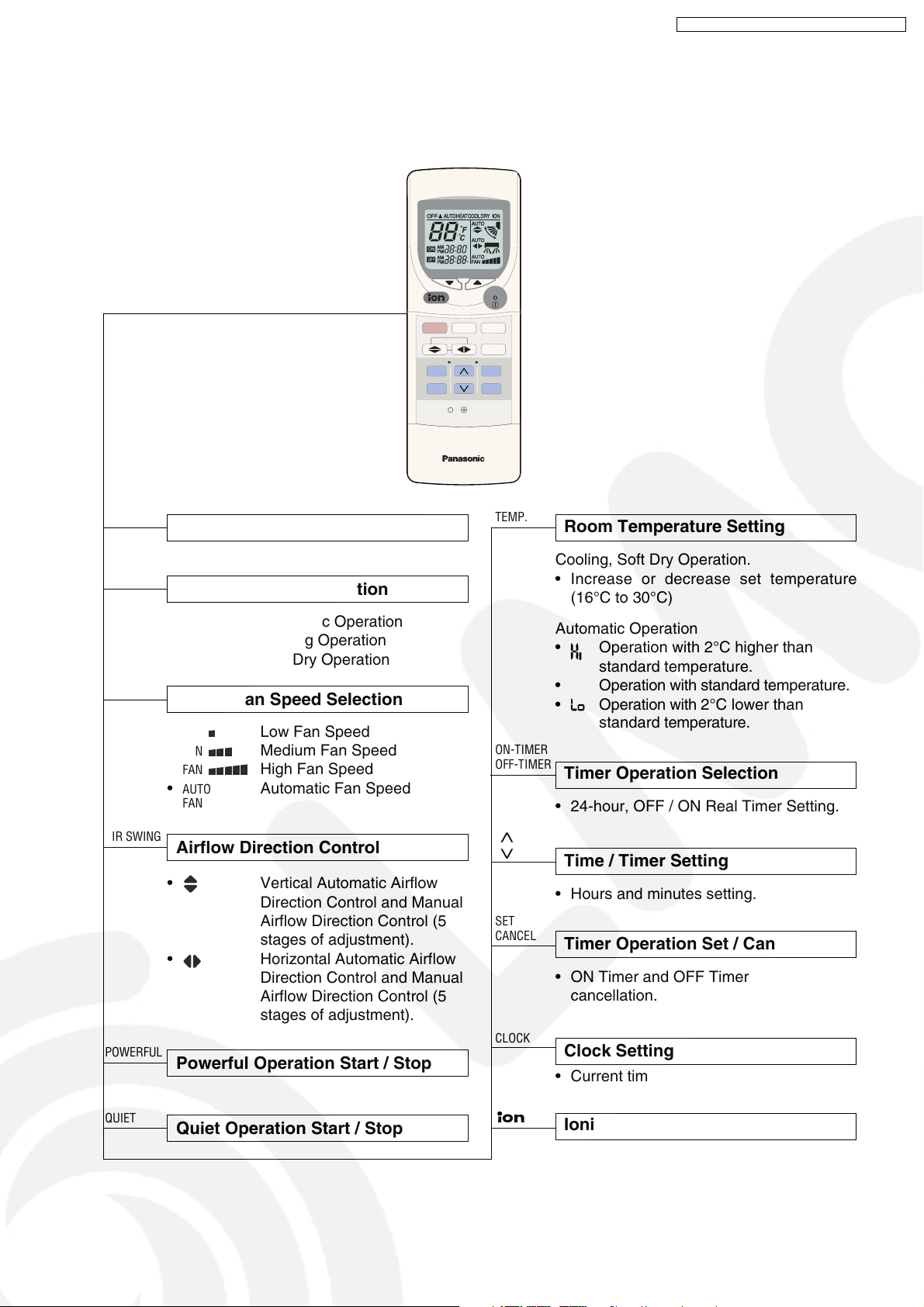
2.1. Remote Control
MODE
OFF
AIR SWING
1
ON
TEMP
QUIET
RESET CLOCK
TIMER
CS-V18DKE CU-V18DKE / CS-V24DKE CU- V24DKE
/
ON
OFF
POWERFUL
FAN SPEED
2
3
SET
CANCEL
OFF / ON I
MODE
FAN SPEED
AIR SWING
POWERFUL
Operation Start / Stop
Operation Mode Selection
•
•
•
AUTO
COOL
DRY
Automatic Operation
Cooling Operation
Soft Dry Operation
Indoor Fan Speed Selection
•
FAN
Low Fan Speed
•
FAN
Medium Fan Speed
•
FAN
High Fan Speed
•
AUTO
FAN
Automatic Fan Speed
Airflow Direction Control
• Vertical Automatic Airflow
Direction Control and Manual
Airflow Direction Control (5
stages of adjustment).
•
Horizontal Automatic Airflow
Direction Control and Manual
Airflow Direction Control (5
stages of adjustment).
Powerful Operation Start / Stop
TEMP.
ON-TIMER
OFF-TIMER
< >
SET
CANCEL
CLOCK
Room Temperature Setting
Cooling, Soft Dry Operation.
• Increase or decrease set temperature
(16°C to 30°C)
Automatic Operation
•
Operation with 2°C higher than
standard temperature.
• Operation with standard temperature.
•
Operation with 2°C lower than
standard temperature.
Timer Operation Selection
• 24-hour, OFF / ON Real Timer Setting.
Time / Timer Setting
• Hours and minutes setting.
Timer Operation Set / Cancel
• ON Timer and OFF Timer setting and
cancellation.
Clock Setting
• Current time setting.
QUIET
Quiet Operation Start / Stop
Ionizer Operation Start / Stop
3
CS-V18DKE CU-V18DKE / CS-V24DKE CU- V24DKE
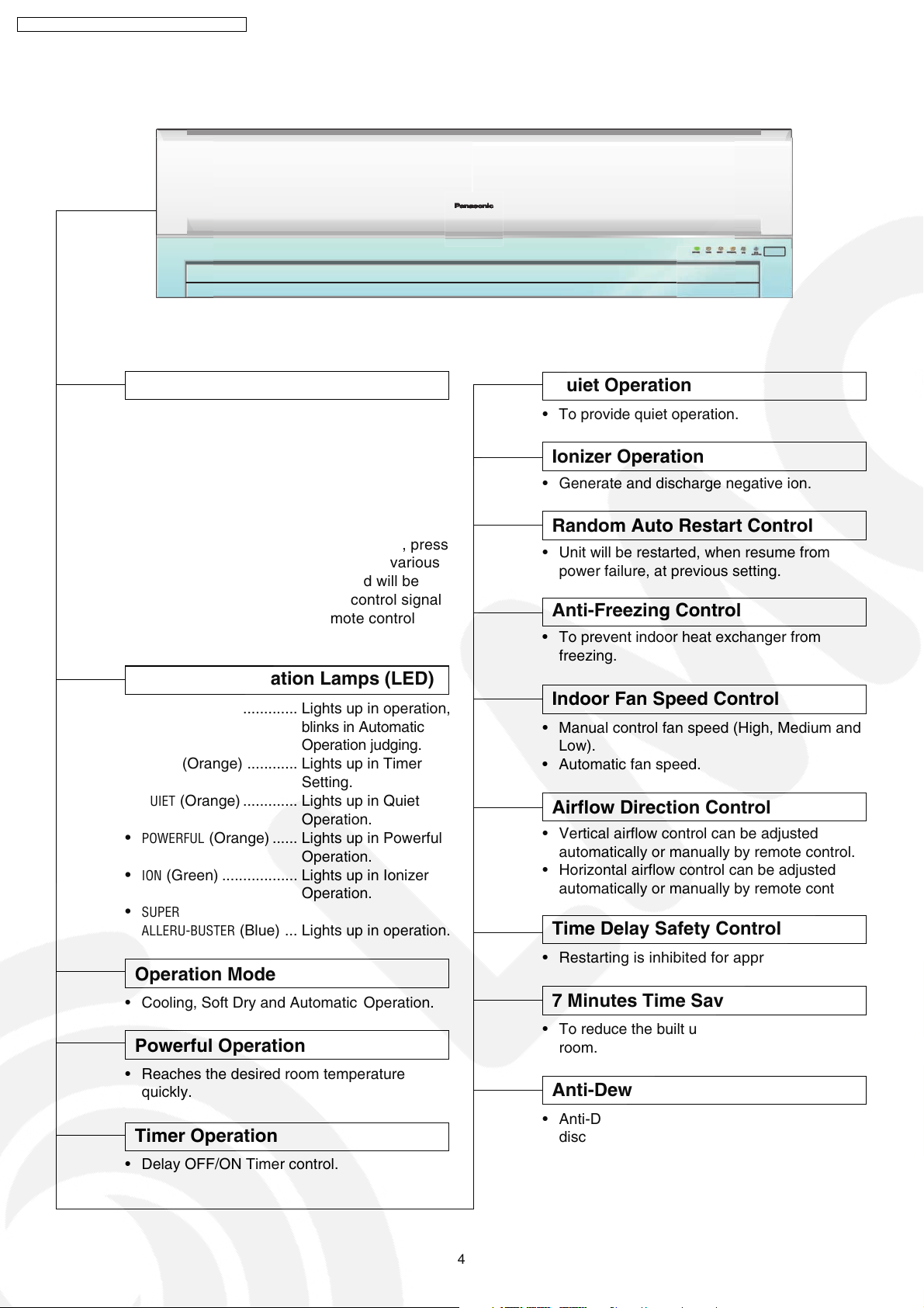
2.2. Indoor Unit
AUTO
OFF / ON
Automatic Operation Button
Quiet Operation
• Press for < 5 second to operate Automatic
operation mode. Used when the remote
control cannot be used.
• Press for ≥ 5 second to operate Cooling
operation mode and compressor force to on
(“beep” sound will heard). Used when test
running or servicing.
• Within 20 second of Cooling operation, press
continuously for ≥ 5 second to enter various
setting mode. “beep, beep” sound will be
heard. (Used to toggle remote control signal
receiving sound or select remote control
transmission code).
Operation Indication Lamps (LED)
•
POWER
(Green) ............. Lights up in operation,
blinks in Automatic
Operation judging.
•
TIMER
(Orange) ............ Lights up in Timer
Setting.
•
QUIET
(Orange) ............. Lights up in Quiet
Operation.
•
POWERFUL
•
ION
•
SUPER
ALLERU-BUSTER
(Orange) ...... Lights up in Powerful
Operation.
(Green) .................. Lights up in Ionizer
Operation.
(Blue) ... Lights up in operation.
• To provide quiet operation.
Ionizer Operation
• Generate and discharge negative ion.
Random Auto Restart Control
• Unit will be restarted, when resume from
power failure, at previous setting.
Anti-Freezing Control
• To prevent indoor heat exchanger from
freezing.
Indoor Fan Speed Control
• Manual control fan speed (High, Medium and
Low).
• Automatic fan speed.
Airflow Direction Control
• Vertical airflow control can be adjusted
automatically or manually by remote control.
• Horizontal airflow control can be adjusted
automatically or manually by remote control.
Time Delay Safety Control
Operation Mode
• Cooling, Soft Dry and Automatic Operation.
Powerful Operation
• Reaches the desired room temperature
quickly.
Timer Operation
• Delay OFF/ON Timer control.
• Restarting is inhibited for appro. 3 minutes.
7 Minutes Time Save Control
• To reduce the built up humidity inside the
room.
Anti-Dew Formation Control
• Anti-Dew Formation Control for indoor unit
discharge area.
4
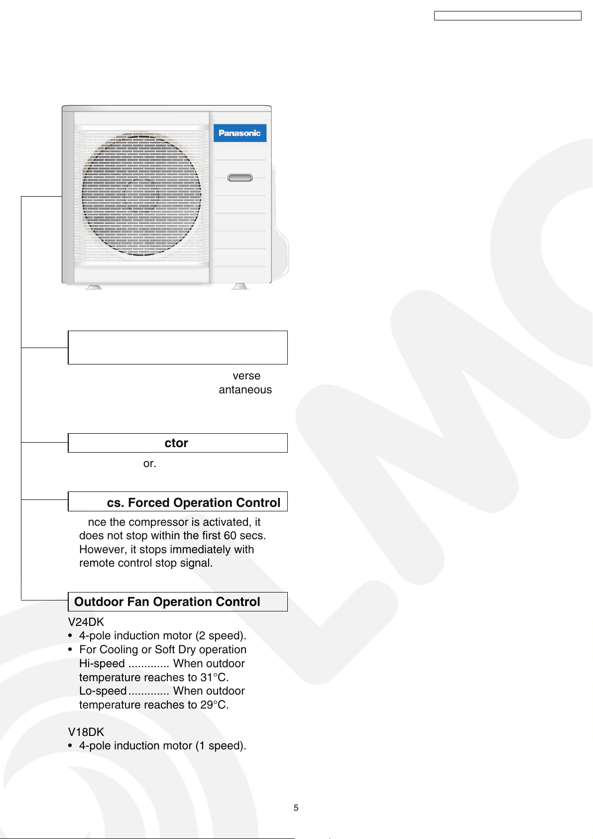
2.3. Outdoor Unit
CS-V18DKE CU-V18DKE / CS-V24DKE CU- V24DKE
Compressor Reverse Rotation
Protection Control
• To protect compressor from reverse
rotation when there is a instantaneous
power failure.
Overload Protector
• Inner protector.
60 Secs. Forced Operation Control
• Once the compressor is activated, it
does not stop within the first 60 secs.
However, it stops immediately with
remote control stop signal.
Outdoor Fan Operation Control
V24DK
• 4-pole induction motor (2 speed).
• For Cooling or Soft Dry operation
Hi-speed ............. When outdoor
temperature reaches to 31°C.
Lo-speed ............. When outdoor
temperature reaches to 29°C.
V18DK
• 4-pole induction motor (1 speed).
5
CS-V18DKE CU-V18DKE / CS-V24DKE CU- V24DKE
3 Product Specifications
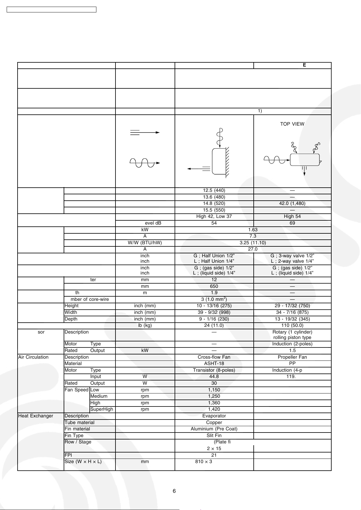
3.1. CS-V18DKE CU-V18DKE
Unit CS-V18DKE CU-V18DKE
Power Source (Phase, Voltage, Cycle) ø,V,Hz Single, 230, 50
Cooling Capacity kW (BTU/h) 5.30 (18,100)
Moisture Removal l/h (Pint/h) 2.9 (6.1)
Airflow Method OUTLET
INTAKE
Air Volume Lo m3/min (cfm) 12.5 (440) —
Me m3/min (cfm) 13.6 (480) —
Hi m3/min (cfm) 14.8 (520) 42.0 (1,480)
SHi m3/min (cfm) 15.5 (550) —
Noise Level dB (A) High 42, Low 37 High 54
Power level dB 54 69
Electrical Data Input Power kW 1.63
Running Current A 7.3
EER W/W (BTU/hW) 3.25 (11.10)
Starting Current A 27.0
Piping Connection Port
(Flare piping)
Pipe Size
(Flare piping)
Drain
Hose
Power Cord Length m 1.9 —
Dimensions Height inch (mm) 10 - 13/16 (275) 29 - 17/32 (750)
Net Weight lb (kg) 24 (11.0) 110 (50.0)
Compressor Description — Rotary (1 cylinder)
Air Circulation Description Cross-flow Fan Propeller Fan
Heat Exchanger Description Evaporator Condenser
Inner diameter mm 12 —
Length mm 650 —
Number of core-wire 3 (1.0 mm2) —
Width inch (mm) 39 - 9/32 (998) 34 - 7/16 (875)
Depth inch (mm) 9 - 1/16 (230) 13 - 19/32 (345)
Motor Type — Induction (2-poles)
Rated Output kW — 1.5
Material ASHT-18 PP
Motor Type Transistor (8-poles) Induction (4-poles)
Input W 44.8 119.6
Rated Output W 30 50
Fan Speed Low rpm 1,150 —
Medium rpm 1,250 —
High rpm 1,360 720
SuperHigh rpm 1,420 —
Tube material Copper Copper
Fin material Aluminium (Pre Coat) Aluminium
Fin Type Slit Fin Corrugated Fin
Row / Stage (Plate fin configuration, forced draft)
FPI 21 16
Size (W × H × L) mm 810 × 315 × 25.4 850.5
inch
inch
inch
inch
SIDE VIEW TOP VIEW
G ; Half Union 1/2”
L ; Half Union 1/4”
G ; (gas side) 1/2”
L ; (liquid side) 1/4”
2×15 2×34
G ; 3-way valve 1/2”
L ; 2-way valve 1/4”
G ; (gas side) 1/2”
L ; (liquid side) 1/4”
rolling piston type
870.5
× 714.0 × 25.4
6

CS-V18DKE CU-V18DKE / CS-V24DKE CU- V24DKE
Unit CS-V18DKE CU-V18DKE
Refrigerant Control Device — Capillary Tube
Refrigeration Oil (cm3) — FV50S (670)
Refrigerant (R410A) g (oz) — 1,340 (47.3)
Thermostat Electronic Control —
Protection Device — Inner Protector
Capillary Tube Length mm — 890
Flow Rate l/min — 15.2
Inner Diameter mm — 1.8
Air Filter Material
Style
Capacity Control Capillary Tube
Compressor Capacitor µF, VAC — 50 µF, 400VAC
Fan Motor Capacitor µF, VAC — 3.5 µF, 450VAC
P.P.
Honeycomb
—
Note:
•
Specifications are subject to change without notice for further improvement.
7
CS-V18DKE CU-V18DKE / CS-V24DKE CU- V24DKE
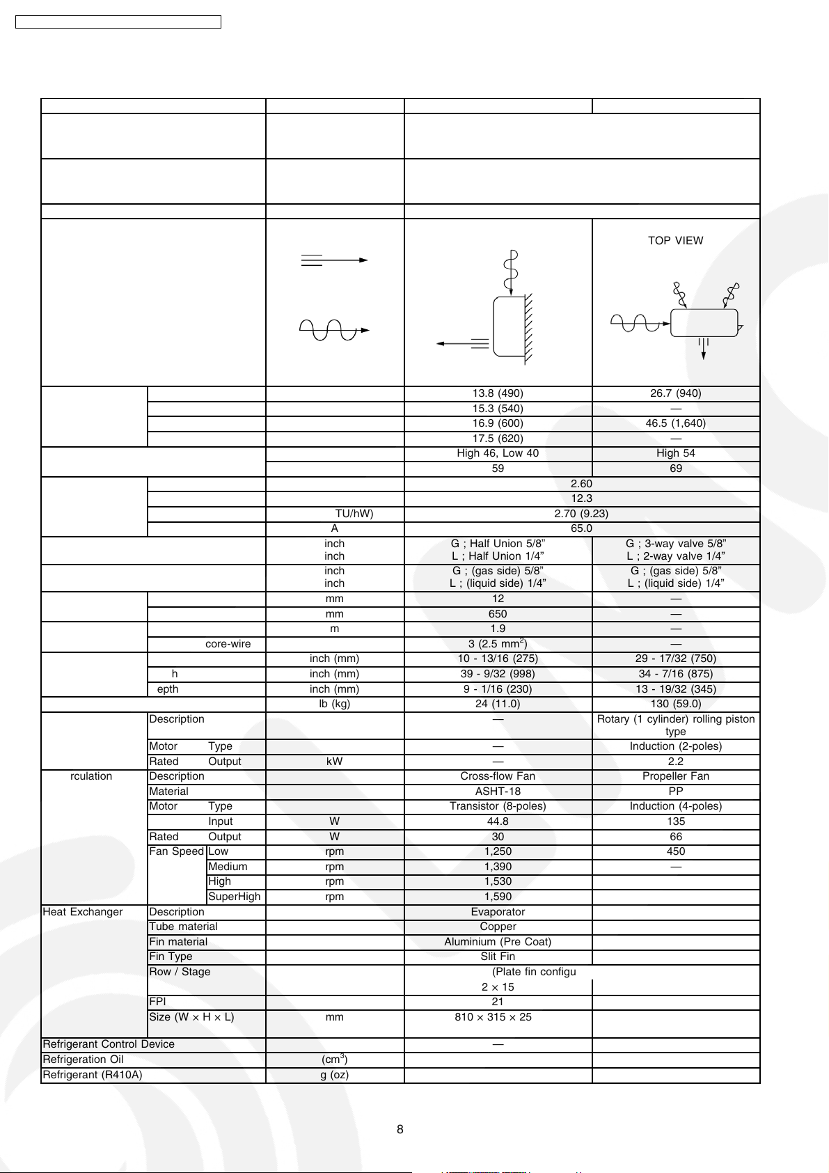
3.2. CS-V24DKE CU-V24DKE
Unit CS-V24DKE CU-V24DKE
Power Source (Phase, Voltage, Cycle) ø,V,Hz Single, 230, 50
Cooling Capacity kW (BTU/h) 7.03 (24,000)
Moisture Removal l/h (Pint/h) 4.0 (8.5)
Airflow Method OUTLET
INTAKE
Air Volume Lo m3/min (cfm) 13.8 (490) 26.7 (940)
Me m3/min (cfm) 15.3 (540) —
Hi m3/min (cfm) 16.9 (600) 46.5 (1,640)
SHi m3/min (cfm) 17.5 (620) —
Noise Level dB (A) High 46, Low 40 High 54
Power level dB 59 69
Electrical Data Input Power kW 2.60
Running Current A 12.3
EER W/W (BTU/hW) 2.70 (9.23)
Starting Current A 65.0
Piping Connection Port
(Flare piping)
Pipe Size
(Flare piping)
Drain
Hose
Power Cord Length m 1.9 —
Dimensions Height inch (mm) 10 - 13/16 (275) 29 - 17/32 (750)
Net Weight lb (kg) 24 (11.0) 130 (59.0)
Compressor Description — Rotary (1 cylinder) rolling piston
Air Circulation Description Cross-flow Fan Propeller Fan
Heat Exchanger Description Evaporator Condenser
Refrigerant Control Device — Capillary Tube
Refrigeration Oil (cm3) — FV50S (1,130)
Refrigerant (R410A) g (oz) — 1,470 (51.9)
Inner diameter mm 12 —
Length mm 650 —
Number of core-wire 3 (2.5 mm2) —
Width inch (mm) 39 - 9/32 (998) 34 - 7/16 (875)
Depth inch (mm) 9 - 1/16 (230) 13 - 19/32 (345)
Motor Type — Induction (2-poles)
Rated Output kW — 2.2
Material ASHT-18 PP
Motor Type Transistor (8-poles) Induction (4-poles)
Input W 44.8 135
Rated Output W 30 66
Fan Speed Low rpm 1,250 450
Medium rpm 1,390 —
High rpm 1,530 785
SuperHigh rpm 1,590 —
Tube material Copper Copper
Fin material Aluminium (Pre Coat) Aluminium
Fin Type Slit Fin Corrugated Fin
Row / Stage (Plate fin configuration, forced draft)
FPI 21 18
Size (W × H × L) mm 810 × 315 × 25.4 850.5
inch
inch
inch
inch
SIDE VIEW TOP VIEW
G ; Half Union 5/8”
L ; Half Union 1/4”
G ; (gas side) 5/8”
L ; (liquid side) 1/4”
2 × 15 2 × 34
G ; 3-way valve 5/8”
L ; 2-way valve 1/4”
G ; (gas side) 5/8”
L ; (liquid side) 1/4”
870.5
type
× 714.0 × 25.4
8
CS-V18DKE CU-V18DKE / CS-V24DKE CU- V24DKE
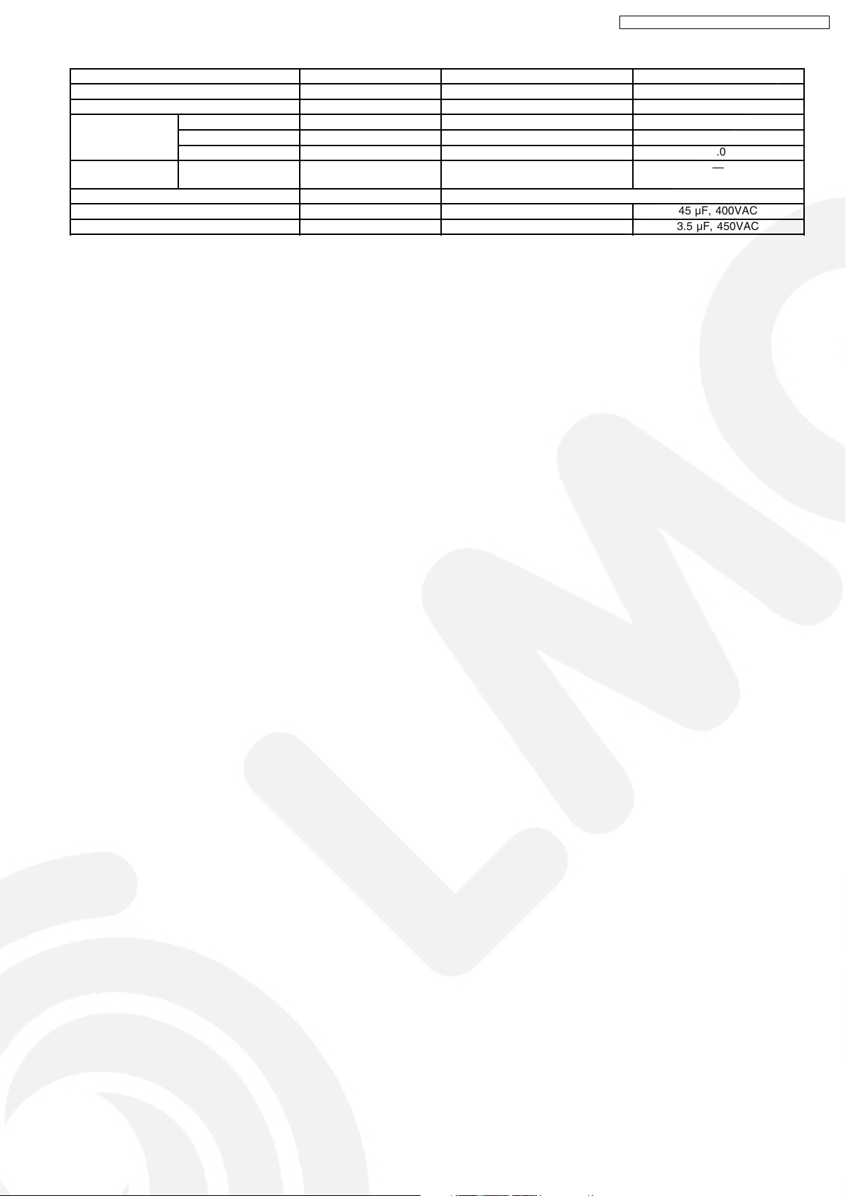
Unit CS-V24DKE CU-V24DKE
Thermostat Electronic Control Mechanical Control
Protection Device — Inner Protector
Capillary Tube Length mm — 645
Flow Rate l/min — 23.5
Inner Diameter mm — 2.0
Air Filter Material
Style
Capacity Control Capillary Tube
Compressor Capacitor µF, VAC — 45 µF, 400VAC
Fan Motor Capacitor µF, VAC — 3.5 µF, 450VAC
P.P.
Honeycomb
—
Note:
•
Specifications are subject to change without notice for further improvement.
9
CS-V18DKE CU-V18DKE / CS-V24DKE CU- V24DKE
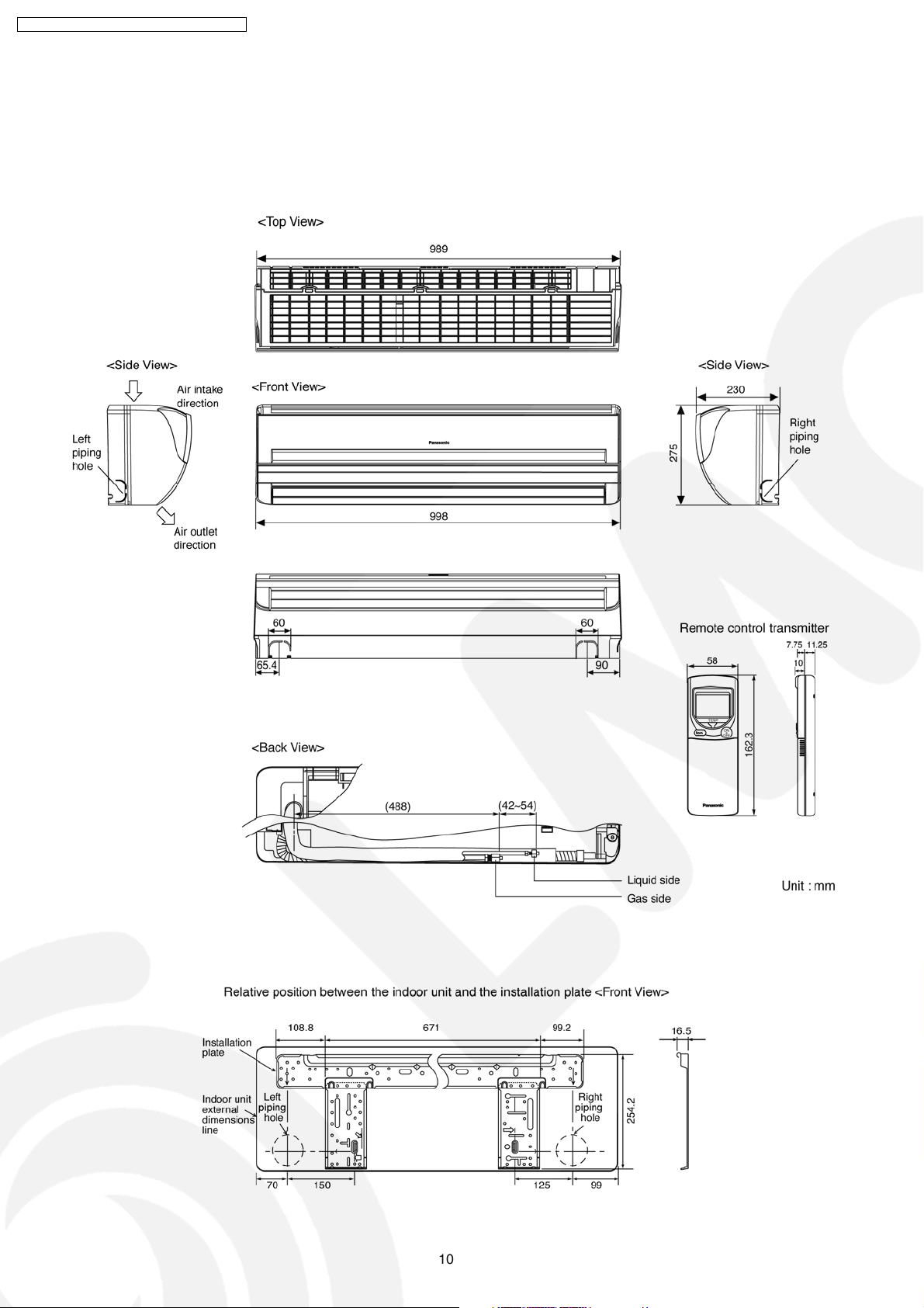
4 Dimensions
4.1. Indoor Unit & Remote Control
4.1.1. CS-V18DKE CS-V24DKE
10
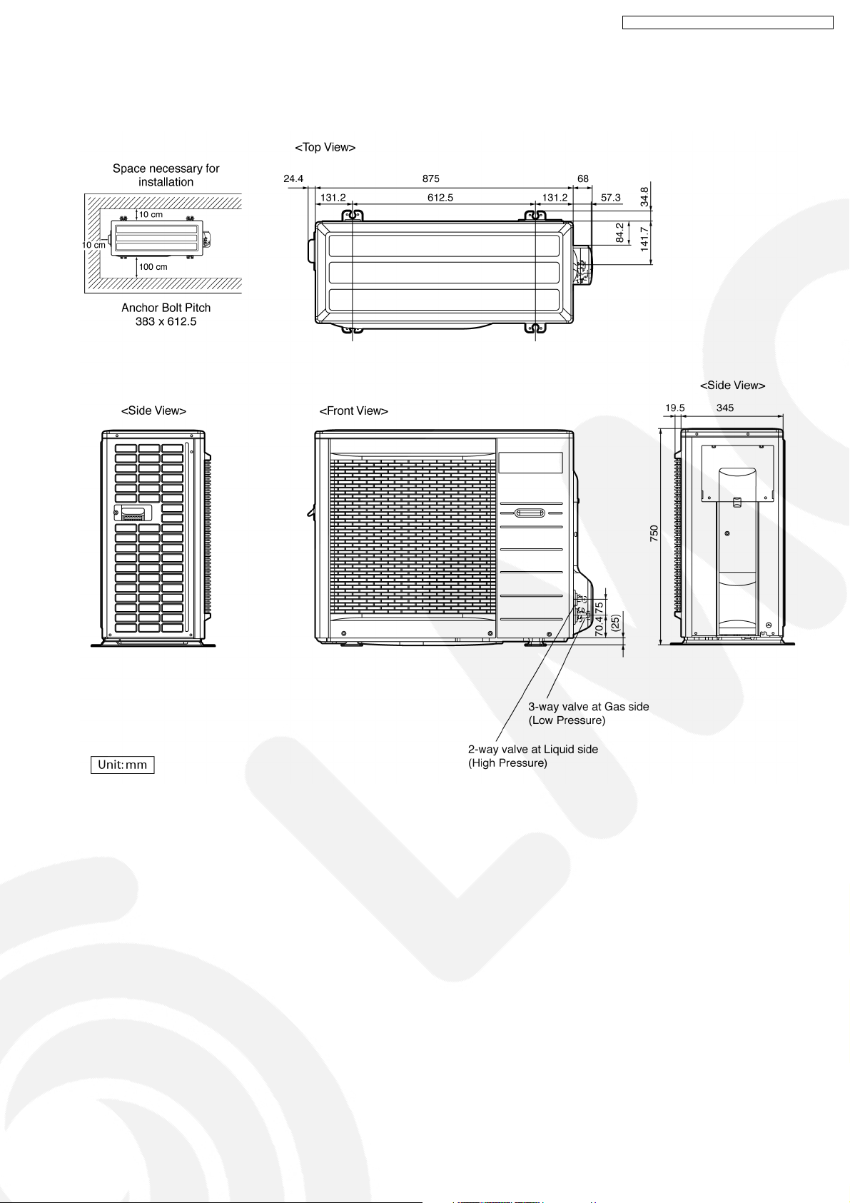
4.2. Outdoor Unit
4.2.1. CU-V18DKE CU-V24DKE
CS-V18DKE CU-V18DKE / CS-V24DKE CU- V24DKE
11
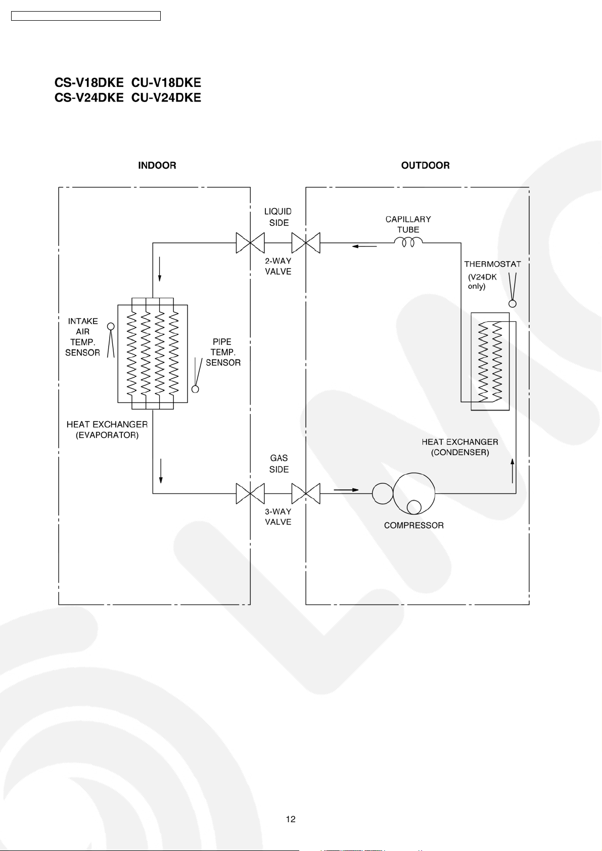
CS-V18DKE CU-V18DKE / CS-V24DKE CU- V24DKE
5 Refrigeration Cycle Diagram
12
6 Block Diagram
CS-V18DKE CU-V18DKE / CS-V24DKE CU- V24DKE
13
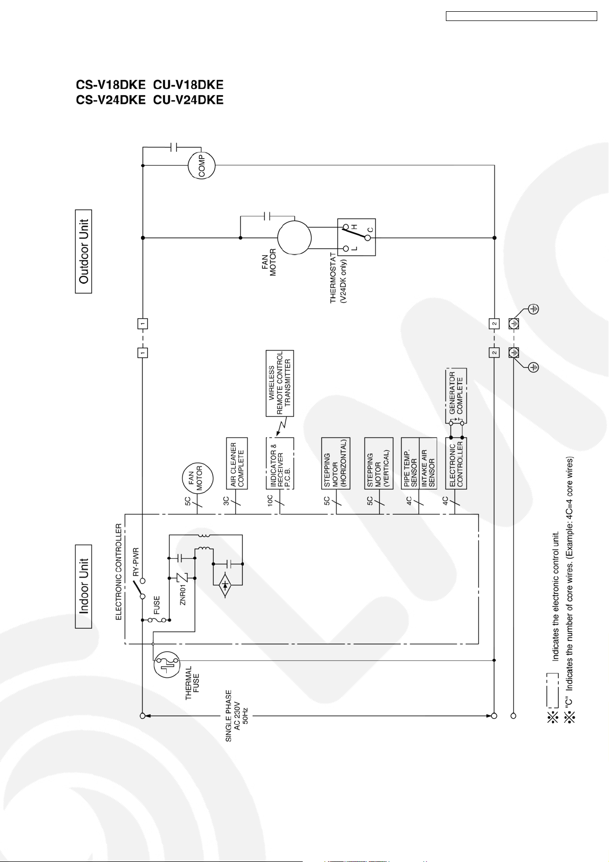
CS-V18DKE CU-V18DKE / CS-V24DKE CU- V24DKE
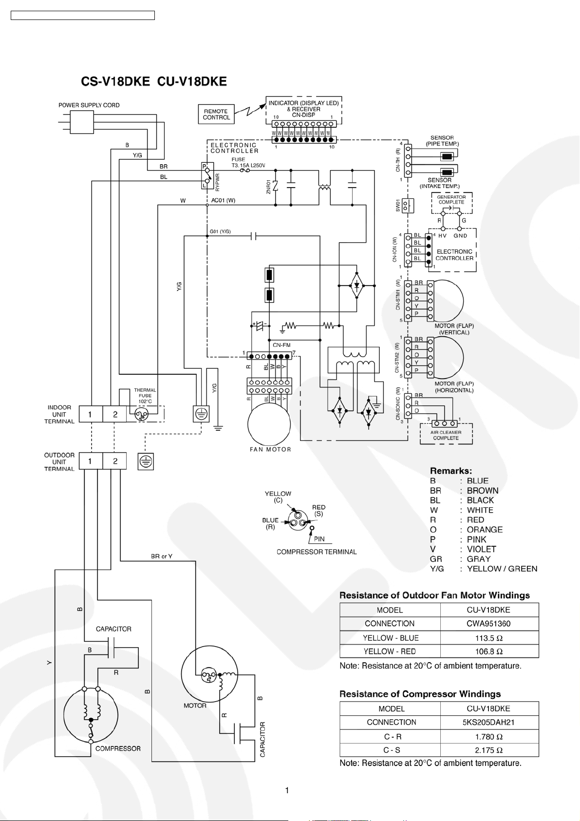
7 Wiring Diagram
14
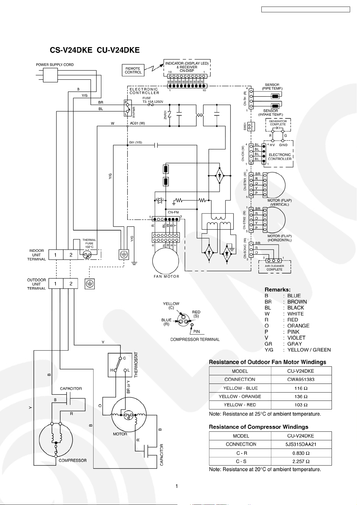
CS-V18DKE CU-V18DKE / CS-V24DKE CU- V24DKE
15
CS-V18DKE CU-V18DKE / CS-V24DKE CU- V24DKE
8 Operation Details
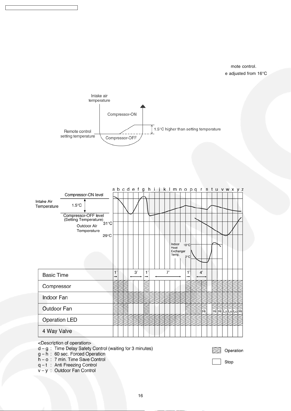
8.1. Cooling Operation
• Cooling operation can be set using remote control.
• This operation is applied to cool down the room temperature reaches the setting temperature set on the remote control.
• The remote control setting temperature, which takes the reading of intake air temperature sensor, can be adjusted from 16°C
to 30°C.
• During cooling operation, the compressor will stop running and restart as shown in below figure.
8.1.1. Cooling Operation Time Diagram
16
CS-V18DKE CU-V18DKE / CS-V24DKE CU- V24DKE
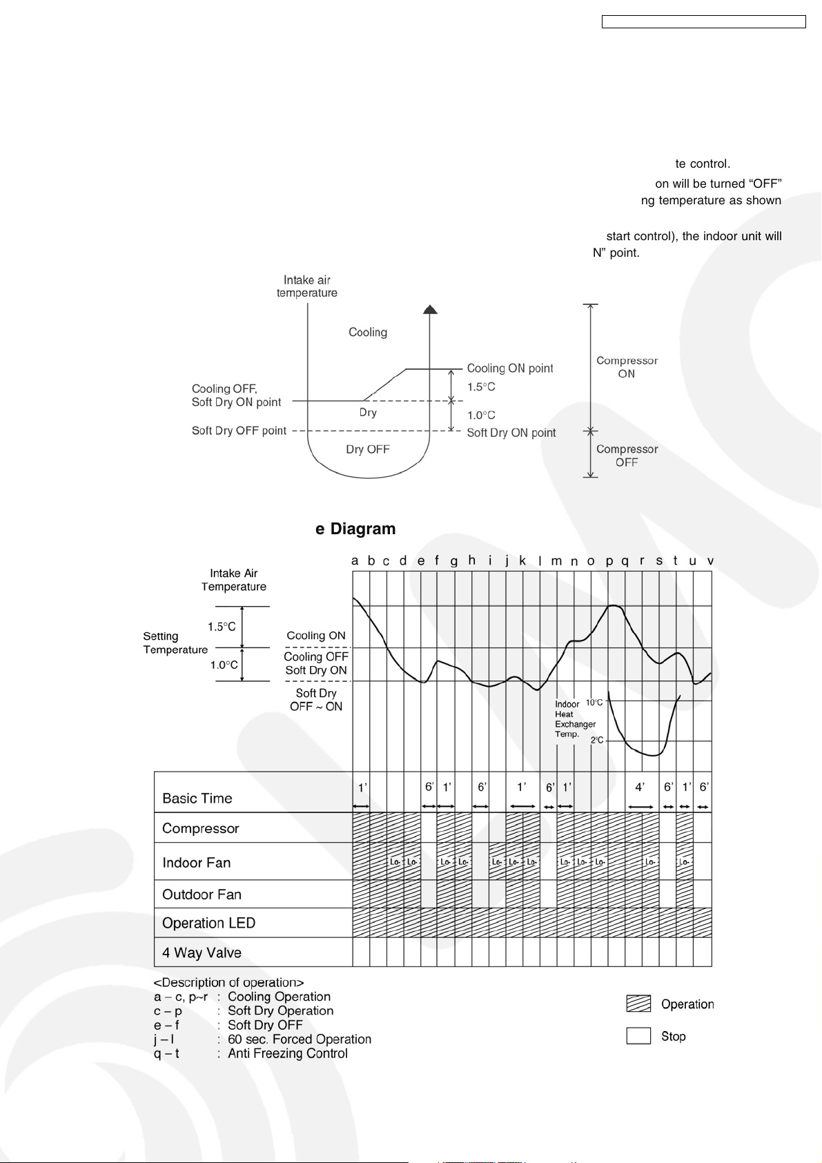
8.2. Soft Dry Operation
• Soft Dry operation can be set using remote control.
• Soft Dry operation is applied to dehumidify and to perform a gentle cooling to the room.
• This operation starts when the intake air temperature sensor reaches the setting temperature on the remote control.
• When operation begins, Soft Dry will be switched “ON” for a maximum 10 minutes, then Soft Dry operation will be turned “OFF”
for a minimum 6 minutes. After that, the Soft Dry operation will be “ON” and “OFF” based on the setting temperature as shown
in below figure.
• However after 3 minutes of compressor off, during Soft Dry “OFF” (within 6 minutes Soft Dry restart control), the indoor unit will
start to operate at normal Cooling mode if the intake temperature is higher than Cooling “ON” point.
8.2.1. Soft Dry Operation Time Diagram
17
CS-V18DKE CU-V18DKE / CS-V24DKE CU- V24DKE
8.3. Automatic Operation
• Automatic operation can be set using remote control.
• This operation starts to operate with indoor fan at SLo speed for 20 seconds to judge the intake air temperature.
• After judged the temperature, the operation mode is determined by referring to the below standard.
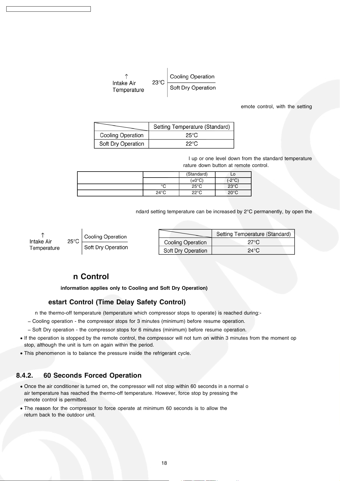
• Then, the unit start to operate at determined operation mode, until it is switched off using remote control, with the setting
temperature as shown in below table.
• The setting temperature for all the operations can be changed one level up or one level down from the standard temperature
as shown in below table by pressing on the temperature up or temperature down button at remote control.
Operation Hi (Standard) Lo
(+2°C) (±0°C) (-2°C)
Cooling 27°C 25°C 23°C
Soft Dry 24°C 22°C 20°C
• The operation mode judging temperature and standard setting temperature can be increased by 2°C permanently, by open the
circuit of JX1 at indoor electronic controller.
8.4. Operation Control
(For 8.5.1 to 8.5.7 information applies only to Cooling and Soft Dry Operation)
8.4.1. Restart Control (Time Delay Safety Control)
• When the thermo-off temperature (temperature which compressor stops to operate) is reached during:-
− Cooling operation - the compressor stops for 3 minutes (minimum) before resume operation.
− Soft Dry operation - the compressor stops for 6 minutes (minimum) before resume operation.
• If the operation is stopped by the remote control, the compressor will not turn on within 3 minutes from the moment operation
stop, although the unit is turn on again within the period.
• This phenomenon is to balance the pressure inside the refrigerant cycle.
8.4.2. 60 Seconds Forced Operation
• Once the air conditio ner is turned on, the compressor will not stop within 60 seconds in a normal operation although the intake
air temperature has reached the thermo-off temperature. However, force stop by pressing the OFF/ON operation button at the
remote control is permitted.
• The reason for the compressor to force operate at minimum 60 seconds is to allow the refrigerant oil run in a full cycle and
return back to the outdoor unit.
18
CS-V18DKE CU-V18DKE / CS-V24DKE CU- V24DKE
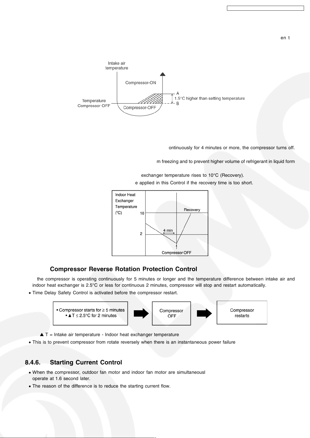
8.4.3. 7 Minutes Time Save Control
• The compressor will start automatically if it has stopped for 7 minutes and the intake air temperature falls between the
compressor ON temperature (A) and compressor OFF temperature (B) during the period.
• This phenomenon is to reduce the built up humidity inside a room.
8.4.4. Anti-Freezing Control
• If the temperature of the indoor heat exchanger falls below 2°C continuously for 4 minutes or more, the compressor turns off.
The fan speed setting remains the same.
• This phenomenon is to protect the indoor heat exchan ger from freezing and to prevent higher volume of refrigerant in liquid form
returning to the compressor.
• Compressor will restart again when the indoor heat exchanger temperature rises to 10°C (Recovery).
• Restart control (Time Delay Safety Control) will be applied in this Control if the recovery time is too short.
8.4.5. Compressor Reverse Rotation Protection Control
• If the compressor is operating continuously for 5 minutes or longer and the temperature difference between intake air and
indoor heat exchanger is 2.5°C or less for continuous 2 minutes, compressor will stop and restart automatically.
• Time Delay Safety Control is activated before the compressor restart.
▲ T = Intake air temperature - Indoor heat exchanger temperature
• This is to prevent compressor from rotate reversely when there is an instantaneous power failure.
8.4.6. Starting Current Control
• When the compressor, outdoor fan motor and indoor fan motor are simultaneously started, the indoor fan motor will start to
operate at 1.6 second later.
• The reason of the difference is to reduce the starting current flow.
19
CS-V18DKE CU-V18DKE / CS-V24DKE CU- V24DKE
8.4.7. Anti-Dew Formation Control
• Purpose is to prevent dew formation on indoor unit air discharge area.
• The following conditio ns occur for 30 minutes continuously, anti-dew formation will activate:
− Remote Control setting temperature is less than 25°C.
− Compressor is on.
− Cooling operation mode.
− Indoor fan motor operate at low fan speed or QLo.
• This control is cancelled immediately when above condition is changed.
• Anti-Dew formation is control by:
1. Lo fan speed
Lo fan is changed to Lo+ fan
2. QLo fan speed
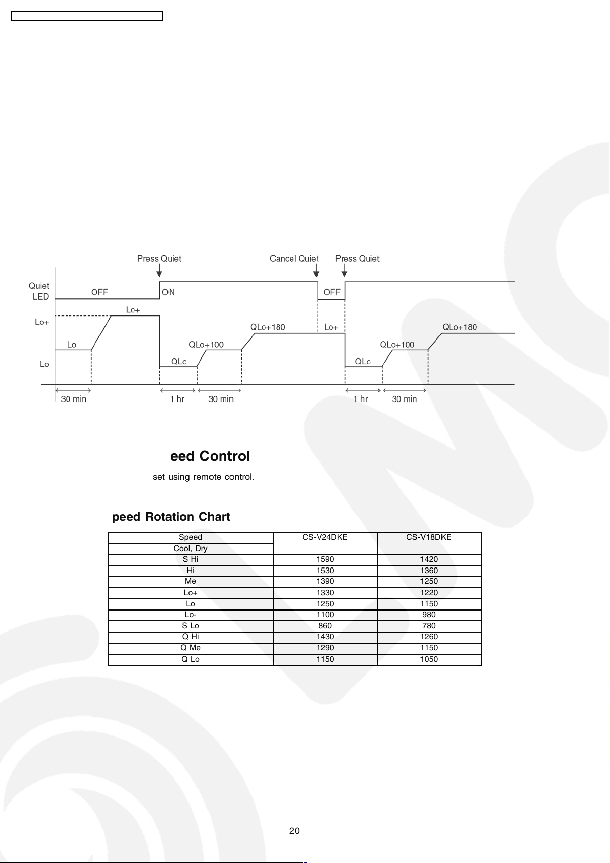
8.5. Indoor Fan Speed Control
• Indoor Fan Speed can be set using remote control.
8.5.1. Fan Speed Rotation Chart
Speed CS-V24DKE CS-V18DKE
Cool, Dry
SHi 1590 1420
Hi 1530 1360
Me 1390 1250
Lo+ 1330 1220
Lo 1250 1150
Lo- 1100 980
SLo 860 780
QHi 1430 1260
QMe 1290 1150
QLo 1150 1050
20
CS-V18DKE CU-V18DKE / CS-V24DKE CU- V24DKE
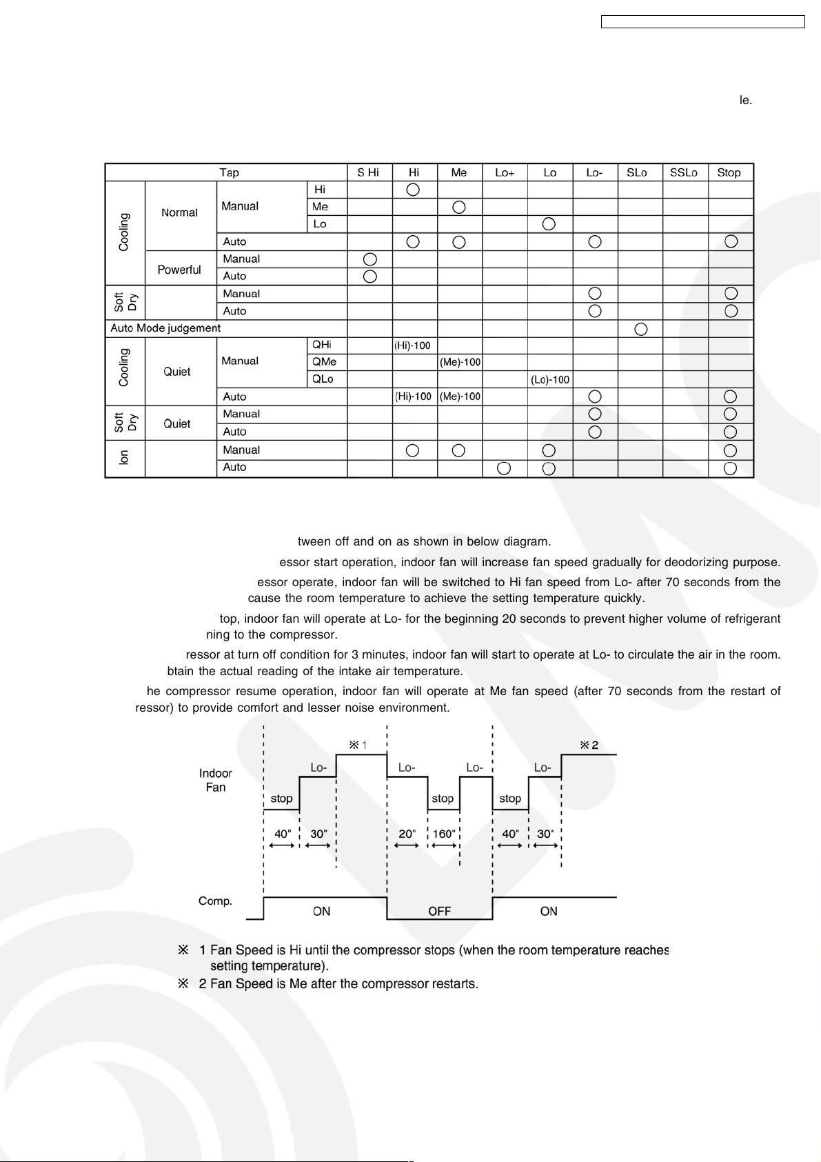
8.5.2. Automatic Fan Speed Control
• When set to Auto Fan Speed, the fan speed is adjusted between maximum and minimum setting as shown in the table.
− Fan speed rotates in the range of Hi, and Me and Lo-.
− Deodorizing Control will be activated.
• Auto Fan Speed during cooling operation:
1. Indoor fan will rotate alternately between off and on as shown in below diagram.
2. At the beginning of each compressor start operation, indoor fan will increase fan speed gradually for deodorizing purpose.
3. For the first time the compressor operate, indoor fan will be switched to Hi fan speed from Lo- after 70 seconds from the
start of compressor. This cause the room temperature to achieve the setting temperature quickly.
4. During compressor stop, indoor fan will operate at Lo- for the beginning 20 seconds to prevent higher volume of refrigerant
in liquid form returning to the compressor.
5. After the compressor at turn off condition for 3 minutes, indoor fan will start to operate at Lo- to circulate the air in the room.
This is to obtain the actual reading of the intake air temperature.
6. When the compressor resume operation, indoor fan will operate at Me fan speed (after 70 seconds from the restart of
compressor) to provide comfort and lesser noise environment.
21
CS-V18DKE CU-V18DKE / CS-V24DKE CU- V24DKE
• Auto Fan Speed during Soft Dry operation:
1. Indoor fan will rotate alternately between off and Lo-.
2. At the beginning of each compressor start operation, indoor fan will increase fan speed gradually for deodorizing purpose.
3. When compressor at turn off condition for 6 minutes, indoor fan will start fan speed at Lo- to circulate the air in the room.
This is to obtain the actual reading of intake air temperature.
8.5.3. Manual Fan Speed Control
• Manual fan speed adjustment can be carried out by using the Fan Speed selection button at the remote control.
• There are 3 types of fan speed settings: Lo, Me, Hi.
8.6. Outdoor Fan Speed Control
• There is only one speed for outdoor fan motor (V18DK).
• There is 2 speed for outdoor fan motor, outdoor fan speed can be changed to Hi or Lo according to outdoor temperature
(V24DK).
• When the air conditioner is turned on, the compressor and the outdoor fan will operate simultaneously .
• Likewise, both compressor and outdoor fan will stop at the same time if the unit is turned off.
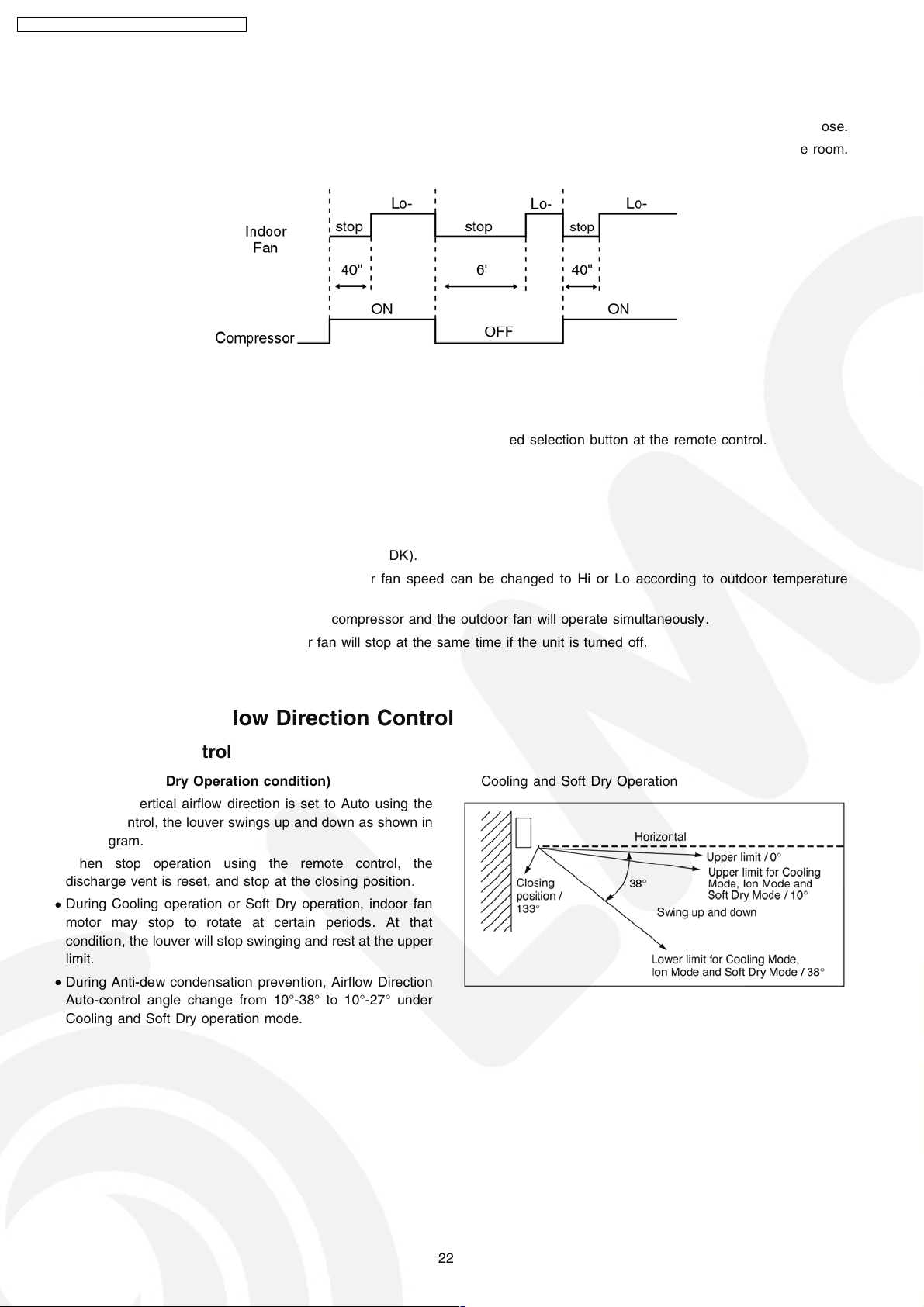
8.7. Vertical Airflow Direction Control
8.7.1. Auto Control
(Cooling and Soft Dry Operation condition)
• When the vertical airflow direction is set to Auto using the
remote control, the louver swings up and down as shown in
the diagram.
• When stop operation using the remote control, the
discharge vent is reset, and stop at the closing position.
• During Cooling operation or Soft Dry operation, indoor fan
motor may stop to rotate at certain periods. At that
condition, the louver will stop swinging and rest at the upper
limit.
• During Anti-dew condensation prevention, Airflow Direction
Auto-control angle change from 10°-38° to 10°-27° under
Cooling and Soft Dry operation mode.
Cooling and Soft Dry Operation
22
CS-V18DKE CU-V18DKE / CS-V24DKE CU- V24DKE
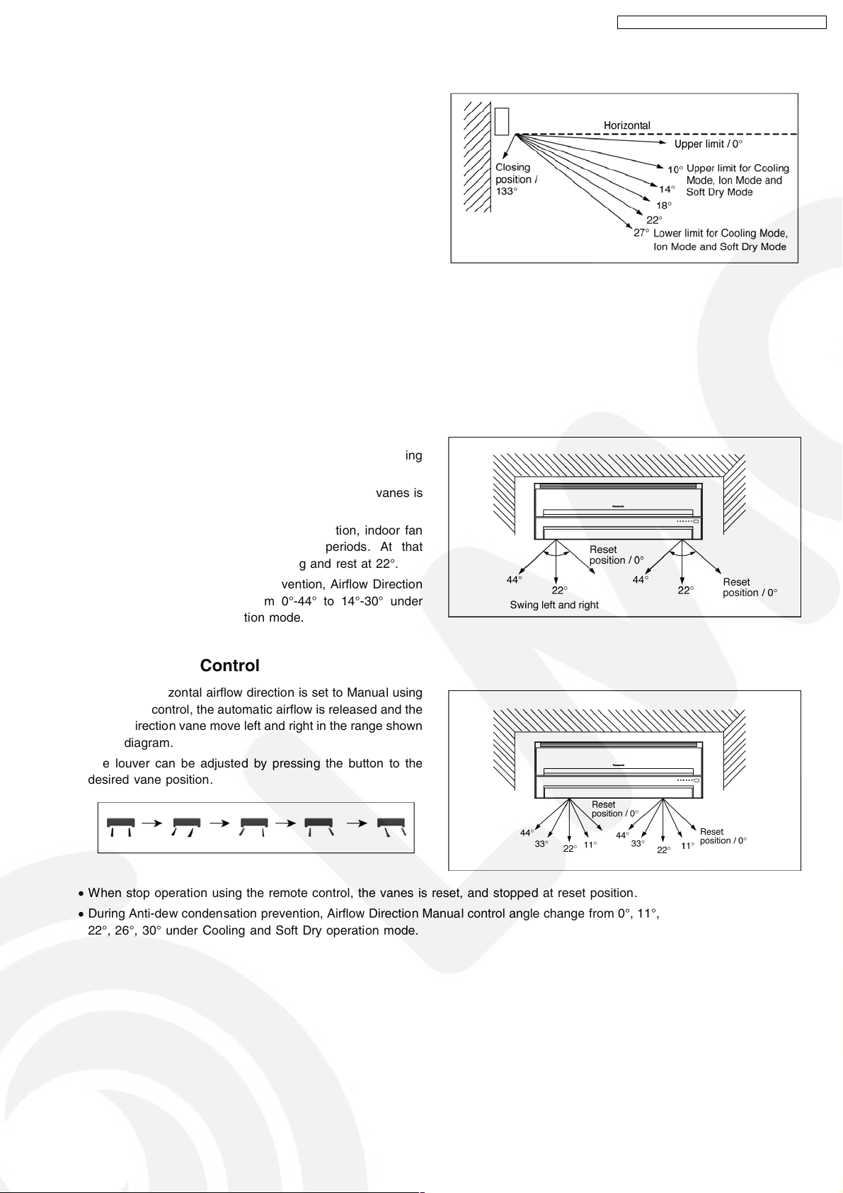
8.7.2. Manual Control
• When the vertical airflow direction is set to Manual using the
remote control, the automatic airflow is released and the
airflow direction louver move up and down in the range
shown in the diagram.
• The louver can be adjusted by pressing the button to the
desired louver position .
• When stop operation using the remote control, the
discharge vent is reset, and stop at the closing position.
• During Anti-dew condensation prevention, Airflow Direction
Manual control angle change from 10°,14°,18°,22°,27° to
10°,13°,16°,19°,22° under Cooling and Soft Dry operation
mode.
8.8. Horizontal Airflow Direction Control
8.8.1. Auto Control
• When the horizontal airflow direction is set to Auto using the
remote control, the vanes swings left and right for Cooling
and Soft Dry (0°-44°) as shown in the diagram.
• When stop operation using the remote control, the vanes is
reset, and stop at the reset position.
• During Cooling operation or Soft Dry operation, indoor fan
motor may stop to rotate at certain periods. At that
condition, the vanes will stop swinging and rest at 22°.
• During Anti-dew condensation prevention, Airflow Direction
Auto-control angle change from 0°-44° to 14°-30° under
Cooling and Soft Dry operation mode.
Cooling and Soft Dry Operation
8.8.2. Manual Control
• When the horizontal airflow direction is set to Manual using
the remote control, the automatic airflow is released and the
airflow direction vane move left and right in the range shown
in the diagram.
The louver can be adjusted by pressing the button to the
desired vane position .
• When stop operation using the remote control, the vanes is reset, and stopped at reset position.
• During Anti-dew condensation prevention, Airflow Direction Manual control angle change from 0°,11°,22°,33°,44° to 14°,18°,
22°,26°,30° under Cooling and Soft Dry operation mode.
23
 Loading...