

Page 1
Order No: PHAAM1111084C1
Installation Manual
Indoor Unit Outdoor Unit
CS-S9NKUW-1
CS-S12NKUW-1
CS-S18NKU-1
CS-S22NKU-1
CU-S9NKU-1
CU-S12NKU-1
CU-S18NKU-1
CU-S22NKU-1
Please file and use this manual together with the service manual for Model No. CU-2S18NBU, Order No. PHAAM1111121C1.
WARNING
This service information is designed for experienced repair technicians only and is not designed for use by the general public.
It does not contain warnings or cautions to advise non-technical individuals of potential dangers in attempting to service a product.
Products powered by electricity should be serviced or repaired only by experienced professional technicians. Any attempt to
service or repair the products dealt with in this service information by anyone else could result in serious injury or death.
PRECAUTION OF LOW TEMPERATURE
In order to avoid frostbite, be assured of no refrigerant leakage during the installation or repairing of refrigerant circuit.
© Panasonic HA Air-Conditioning (M) Sdn. Bhd. 2011.
Unauthorized copying and distribution is a violation of law.
Page 2
10. Installation Instruction
10.1 S9NKUW-1 S12NKUW-1
10.1.1 Select the Best Location
10.1.1.1 Indoor Unit
x Do not install the unit in excessive oil fume area
such as kitchen, workshop
There should not be any heat source or
x
near the unit.
x
There should not be any obstacles blocki
circulation.
x
A place where air circulation in the room
x
A place where drainage can be ea
A place where noise prevention is taken
x
c
onsiderat
Do not install the unit near a door
x
x Ensure the spaces indicated by arrows from the
wall, ceili
Recommended installation height for ind
x
shall be at least 8.2 ft.
ion.
ng, fence or other obstacles
and etc.
steam
ng the air
is good.
sily done.
into
way.
.
oor unit
10.1.1.2 Outdoor Unit
x If an awning is built over the unit to prevent direct
sunli
ght or rain, be careful that heat radiat
the con
x There should not be any animal or plant which
coul
Keep the spaces indicated by arrows from
x
ceiling, fence or other obstacles.
x
Do not place any obstacles
sho
x
If piping length is over the [piping length
addition
adde
denser is not obstru
d be affected by hot air discharg
rt circuit of the discharg
al gas], additional refrigerant sh
d as shown in the tabl
cted.
which may cause a
ed air.
e.
ion from
ed.
wall,
for
ould be
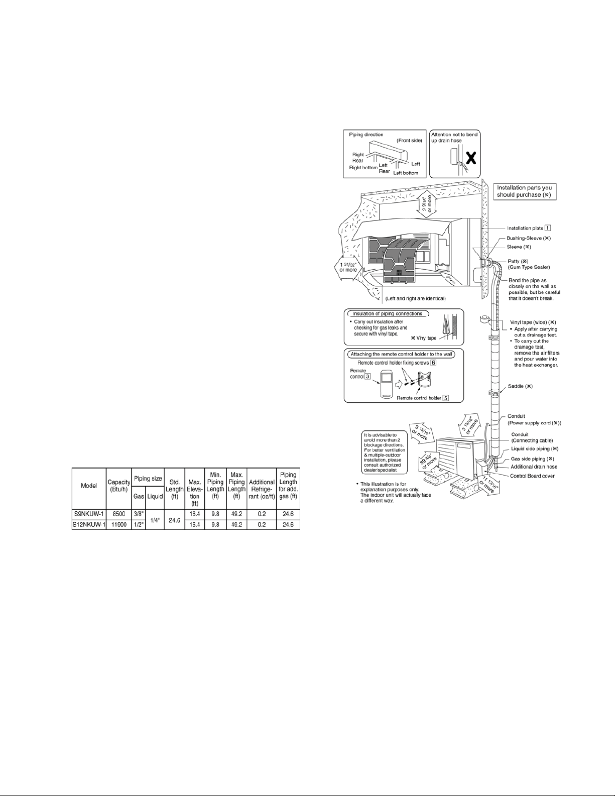
10.1.2 Indoor/Outdoor Unit Installation
Diagram
Example: For S9NKUW-1
If the unit is installe
additional refrigerant should be 1.64 oz .... (32.8 - 24.6)
ft x 0.2 oz/ft = 1.64 oz.
d at 32.8 ft distance, the quantity of
31
Page 3
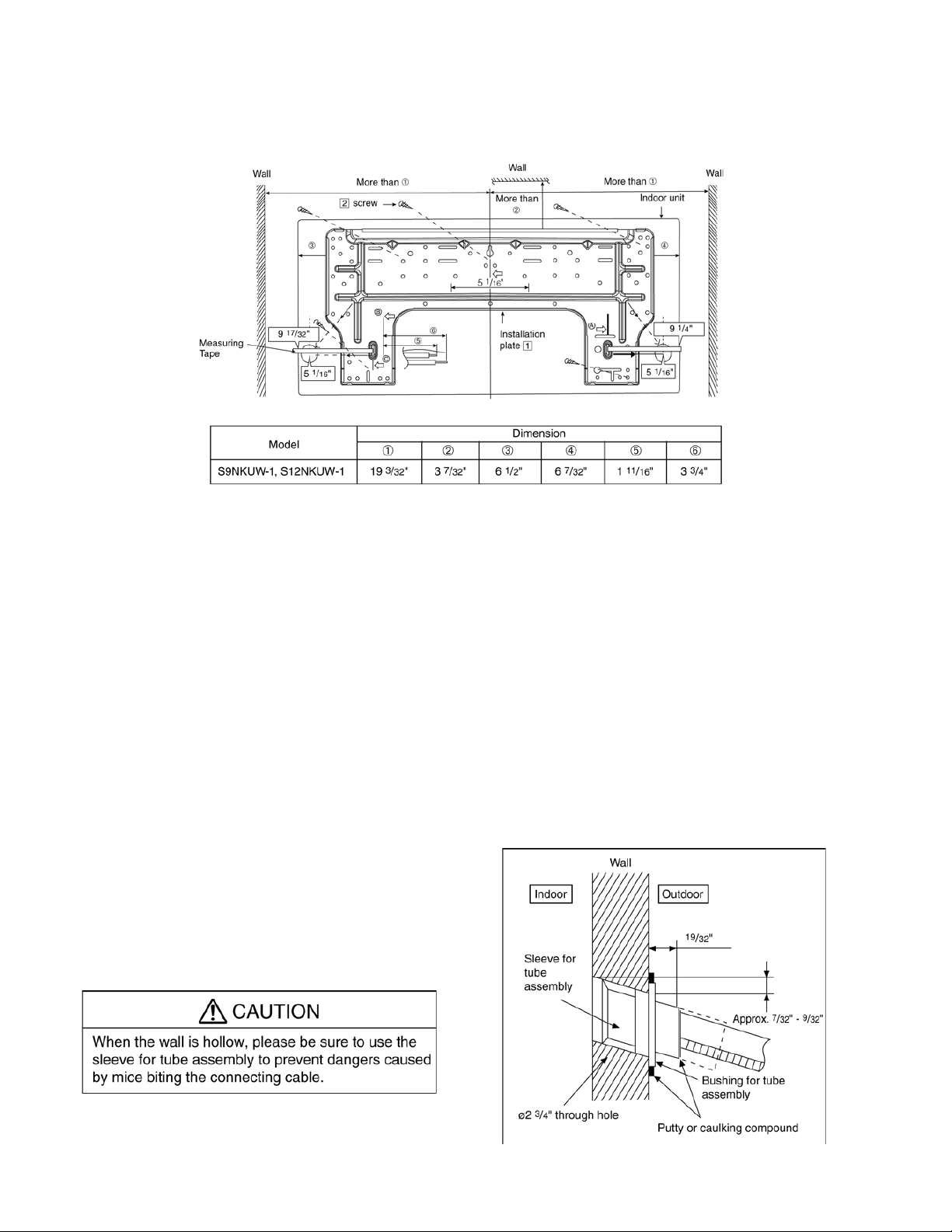
10.1.3 Indoor Unit
10.1.3.1 How to Fix Installation Plate
The mounting wall shall be strong and solid enough to prevent if from the vibration.
The ce
ntre of installation plate should be at more than c at right and left of the wall.
The distance from installation plate edge to ceiling should more than d.
From installation plate left edge to unit’s left side is e.
From installation plate right edge to unit’s right side is f.
B : For left side piping, piping connection for liquid should be about g from this line.
ƻ
: For left side piping, piping connection for gas should be about h from this line.
1 Mount the installation plate on the wall with 5 screws or more (at least 5 screws).
(If mounting the unit on the concrete wall, consider using anchor bolts.)
o Always mount the installation plate horizontally by aligning the marking-off line with the thread and us
a level gaug
2 Drill the piping plate hole with ø2 ¾” hole-core drill.
o Line according to the left and right side of the installation plate. The meeting point of the extended lin
the cente
above. The h
r
espec
o
Drill the piping hole at either the right or the left and the hole should be slightly slanting to the outdoo
side.
e.
r of the hole. Another method is by putting measuring tape at position as sh
ole center is obtained by measuring the distance namely 5 1/16” for left and righ
tively.
10.1.3.2 To Drill a Hole in the Wall and
Install a Sleeve of Piping
1 Insert the piping sleeve to the hole.
2 Fix the bushing to the sleeve.
3 Cut the sleeve until it extrudes about 19/32”
from the wall.
ing
e is
own in the diagram
t hole
r
4
Finish by sealing the sleeve with putty or
caulking compound at the final stage.
32
Page 4
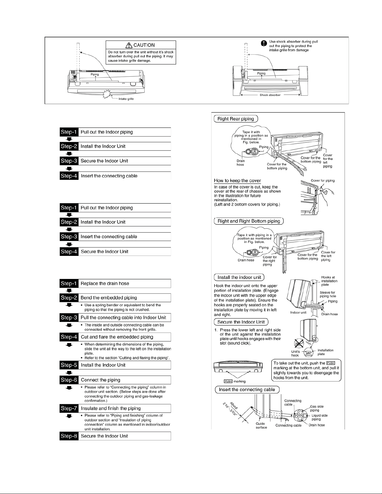
10.1.3.3 Indoor Unit Installation
10.1.3.4 For the right rear piping
10.1.3.5 For the right bottom piping
10.1.3.6 For the embedded piping
(Thi
s can be used for left rear piping and bottom
piping also.)
33
Page 5
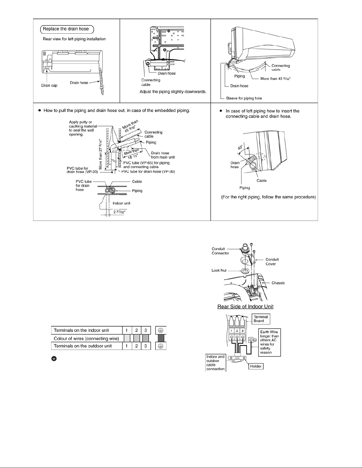
10.1.3.7 Connect the Cable to the Indoor Unit
1. The inside and outside connecting cable can
be co
nnected without remo
Unscrew the conduit cove
2.
nector to conduit cove
con
se
cure it against chassi
3.
Connecting wire between indoor unit an
r unit should be UL listed or
outdoo
approved 4 condu
in accordan
Ensure the colour of wires of outdoor un
o
and terminal number are the same as the
indoo
r's resp
This equipment must be properly earthed.
o Earth lead wire shall be
(Y/G) in colou
other lead wires as shown in the figure fo
electri
cal safety in case of the slip
ctor wires minimum AWG1
ce with local electric code
ectively.
r and shall be longer than
ving the front grille.
r and fix the conduit
r with lock nut, then
s.
d
CSA
6
s.
it
Yellow/Green
r
ping.
34
Page 6
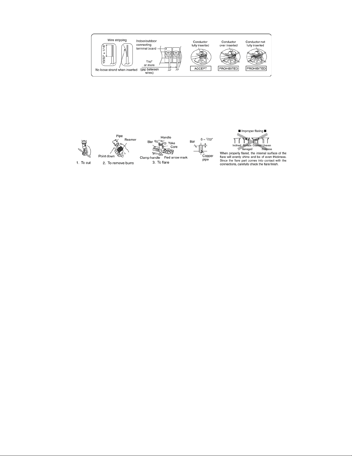
10.1.3.8 Wire Stripping and connecting requirement
10.1.3.9 Cutting and flaring the piping
1 Please cut using pipe cutter and then remove the burrs.
2 Remove the burrs by using reamer. If burrs is not removed, gas leakage may be caused. Turn the piping end
down to avoid the metal powder entering the pipe.
3 Please make flare after inserting the flare nut onto the copper pipes.
35
Page 7

10.1.4 Outdoor Unit
10.1.4.1 Install the Outdoor Unit
x After selecting the best location, start installation to Indoor/Outdoor Unit Installation Diagram.
1
Fix the unit on concrete or rigid frame firmly and horizontally by bolt nut (ø13/32
When installing at roof, please consider strong wind and earthqua
2
ke.
”).
Please fasten the installation stand firmly with bolt or nails.
Model A B C D
S9NKUW-1,
S12NKUW-1
22 7/16” 4 1/8” 23/32” 12 19/32”
10.1.4.2 Connect the Piping
Do not over tighten, over tightening may cause gas leakage.
10.1.4.2.1 Connecting the piping to
indoor
Please make flare after inserting flare nut (locate at
joint portion of tube assembly) onto the copper pipe.
(In case of using long piping)
Connect the piping
x Align the center of piping and suffici
the flare nut with fingers.
x
Further tighten the flare nut with torque wren
cified torque as stated in
spe
the table.
ently tighten
ch in
Piping size Torque
1/4” 13.3 lbf.ft
3/8” 31.0 lbf.ft
1/2” 40.6 lbf.ft
5/8” 47.9 lbf.ft
3/4” 73.8 lbf.ft
10.1.4.2.2 Connecting the piping to
outdoor
Decide piping length and then cut by using pipe cutter.
Remove burrs from cut edge.
Make flare after inserting the flare nut (locate at valve)
onto the copper pipe.
Align center of piping to valve and then tighten with
torque wrench to the specified torque as stated in the
table.
10.1.4.2.3 Connecting the piping to outdoor multi
Decide piping length and then cut by using pipe cutter. Remove burrs from cut edge.
Make flare after inserting the flare nut (locate at valve) onto the copper pipe.
Align center of piping to valve and then tighten with torque wrench to the specified torque as stated in the table.
36
Page 8

10.1.4.2.4 Gas leak checking
Pressure test to system to 400 PSIG with dry nitrogen, in stages. Thoroughly leak check the system.
If the pressure holds, release the nitrogen and proceed to section 10.1.4.3.
10.1.4.3 Evacuation of the equipment
When installing an air conditioner, be sure to evacuate the air inside the indoor unit and pipes in the following
procedures.
1.
Connect a charging hose with a push pin to the Low side of a charging set and the service port of the 3-wa
valve.
Connect the micron gauge between vacuum pump and service port of outdoor un
2.
Turn on the power switch of the vacuum pump and make sure that connect digital micron gauge
3.
down to a value of 500 microns.
To make sure micron gauge a value 500 microns and close the low side valve of the charging set and turn of
4.
the vacuum pump.
Disconnect the vacuum pump hose from the service po
5.
6.
Tighten the service port caps of the 3-way valve at a torque of 13.3 Ibf.ft
7. Remove the valve caps of both of the 2-way valve and 3-way valve. Position both of the valves to “Op
g a hexagonal wrench
usin
Mount valve caps onto the 2-way valve and the 3-wa
8.
o
Be sure to check for gas leaka
(5/32”).
ge.
rt of the 3-way valve.
with a torque wrench.
y valve.
its.
10.1.4.4 Connect the Cable to the Outdoor Unit
1. Remove Top panel.
2. Remove Control Board Cover (Resin and
emove Plugs
3.R
Fix the conduit connectors to the knockout holes
4.
lock-n
uts, then secure them against the side pa
5.
All wires pass through condu
Connecting wire between indoor unit and outdoor unit
6.
should be UL listed or CSA approved 4 condu
wire
s minimum AWG16 in accordance
c code
electri
Wire connection to the power supply (208/230V 60Hz)
7.
throug
h circui
Connect the UL listed or CSA approved wire
o
minimum AWG14 to the terminal boa
con
GFCI.
Connect the power supply cord and connecting
8.
betwe
en indoor unit and outdoor unit according to the diagram below
.
its.
s.
t breaker.
nect the other end of the wires to EL
Metal).
ctor
with local
rd,
and
CB /
with
nel.
s
wire
.
y
and to pull
f
en”
37
Page 9

Secure the wire onto the control board wi
9.
(clamper).
10.
After completing wiring connections, re
board cove
original position with the screws.
11. For wire stripping and connection requirement, refe
ruction g of indoor un
inst
This equipment must be properly earthed.
o Earth lead wire shall be Yellow/Green (Y/G) in colour
r (Metal and Resin) and the top pan
it.
and shall be longer than other lead wires as shown in
the figure for electrical safety in case of the slip
th the holder
attach the control
el to the
r to
ping.
10.1.4.5 Piping Insulation
1. Please carry out insulation at pipe connection portion as mentioned in Indoor/Outdoor Unit Installation
Diag
ram. Please wrap the insulated piping end to prevent water from going inside
If drain hose or connecting piping is in the room (where dew may form), please increase the insulation
2.
g POLY-E FOAM with thickn
usin
ess ¼” or above.
the piping.
by
38
Page 10

10.2 S18NKU-1 S22NKU-1
10.2.1 Select the Best Location
10.2.1.1 Indoor Unit
x Do not install the unit in excessive oil fume areas
su
ch as kitchens, workshops etc.
x There should not be any heat source or
near the unit.
x
There should not be any obstacles blocki
circulation.
x
A place where air circulation in the room
x
A place where drainage can be ea
A place where noise prevention is taken
x
c
onsiderat
Do not install the unit near
x
x Ensure the spaces indicated by arrows from the
wall, ceili
Recommended installation height for ind
x
shall be at least 8.2 ft.
ion.
a doorway.
ng, fence or other obstacles
steam
ng the air
is good.
sily done.
into
.
oor unit
10.2.1.2 Outdoor Unit
x If an awning is built over the unit to prevent direct
sunli
ght or rain, be careful that heat radiat
the con
x There should not be any animal or plant which
coul
Keep the spaces indicated by arrows from
x
ceiling, fence or other obstacles.
x
Do not place any obstacles
sho
x
If piping length is over the [piping length
addition
adde
x
Recommended installation height for outdoor un
sho
denser is not obstru
d be affected by hot air discharg
rt circuit of the discharg
al gas], additional refrigerant sh
d as shown in the tabl
uld be above the seasonal snow
cted.
which may cause a
ed air.
e.
ion from
ed.
wall,
for
ould be
level.
10.2.2 Indoor/Outdoor Unit Installation
Diagram
it
Example: For S18NKU-1
If the unit is installe
additional refrigerant should be 1.64 oz .... (41 - 32.8)
ft x 0.2 oz/ft = 1.64 oz.
d at 41 ft distance, the quantity of
39
Page 11

10.2.3 Indoor Unit
10.2.3.1 How to Fix Installation Plate
The mounting wall must be strong and solid enough to prevent if from the vibration.
The ce
ntre of installation plate should be at more than c at right and left of the wall.
The distance from installation plate edge to ceiling should more than d.
From installation plate left edge to unit’s left side is e.
From installation plate right edge to unit’s right side is f.
B : For left side piping, piping connection for liquid should be about g from this line.
ƻ
: For left side piping, piping connection for gas should be about h from this line.
1 Mount the installation plate on the wall with 5 screws or more (at least 5 screws).
(If mounting the unit on the concrete wall, consider using anchor bolts.)
o Always mount the installation plate horizontally by aligning the marking-off line with the thread and us
a level gaug
2 Drill the piping plate hole with ø2 ¾” hole-core drill.
o Line according to the left and right side of the installation plate. The meeting point of the extended lin
the cente
above. The h
r
espec
o
Drill the piping hole at either the right or the left and the hole should be slightly slanting to the outdoo
side.
e.
r of the hole. Another method is by putting measuring tape at position as sh
ole center is obtained by measuring the distance namely 5 1/16” for left and righ
tively.
10.2.3.2 To Drill a Hole in the Wall and
Install a Sleeve of Piping
1 Insert the piping sleeve to the hole.
2 Fix the bushing to the sleeve.
3 Cut the sleeve until it extrudes about 19/32”
from the wall.
ing
e is
own in the diagram
t hole
r
4
Finish by sealing the sleeve with putty or
caulking compound at the final stage.
40
Page 12

10.2.3.3 Indoor Unit Installation
10.2.3.4 For the right rear piping
10.2.3.5 For the right bottom piping
10.2.3.6 For the embedded piping
(Thi
s can be used for left rear piping and bottom
piping also.)
41
Page 13

10.2.3.7 Connect the Cable to the Indoor Unit
1. The inside and outside connecting cable can
be co
nnected without remo
Unscrew the conduit cove
2.
nector to conduit cove
con
se
cure it against chassi
3.
Connecting wire between indoor unit an
r unit should be UL listed or
outdoo
approved 4 condu
in accordan
Ensure the colour of wires of outdoor un
o
and terminal number are the same as the
indoo
r's resp
This equipment must be properly earthed.
o Earth lead wire shall be
(Y/G) in colou
other lead wires as shown in the figure fo
electri
cal safety in case of the slip
ctor wires minimum AWG1
ce with local electric code
ectively.
r and shall be longer than
ving the front grille.
r and fix the conduit
r with lock nut, then
s.
d
CSA
6
s.
it
Yellow/Green
r
ping.
42
Page 14

10.2.3.8 Wire Stripping and connecting requirement
10.2.3.9 Cutting and flaring the piping
1 Please cut using pipe cutter and then remove the burrs.
2 Remove the burrs by using reamer. If burrs is not removed, gas leakage may be caused. Turn the piping end
down to avoid the metal powder entering the pipe.
3 Please make flare after inserting the flare nut onto the copper pipes.
43
Page 15

10.2.4 Outdoor Unit
10.2.4.1 Install the Outdoor Unit
x After selecting the best location, start installation to Indoor/Outdoor Unit Installation Diagram.
1
Fix the unit on concrete or rigid frame firmly and horizontally by bolt nut (ø13/32
When installing at roof, please consider strong wind and earthqua
2
ke.
Please fasten the installation stand firmly with bolt or nails.
Model A B C D
S18NKU-1,
S22NKU-1
”).
24 1/8” 5 5/32” 5/8” 14 3/32”
10.2.4.2 Connect the Piping
10.2.4.2.1 Connecting the piping to
indoor
Please make flare after inserting flare nut (locate at
joint portion of tube assembly) onto the copper pipe.
(In case of using long piping)
Do not over tighten, over tightening may cause gas leakage.
Piping size Torque
1/4” 13.3 lbf.ft
3/8” 31.0 lbf.ft
1/2” 40.6 lbf.ft
5/8” 47.9 lbf.ft
3/4” 73.8 lbf.ft
Connect the piping
x Align the center of piping and suffici
ently tighten
the flare nut with fingers.
x
Further tighten the flare nut with torque wren
cified torque as stated in
spe
the table.
ch in
10.2.4.2.2 Connecting the piping to
outdoor
Decide piping length and then cut by using pipe cutter.
Remove burrs from cut edge.
Make flare after inserting the flare nut (locate at valve)
onto the copper pipe.
Align center of piping to valve and then tighten with
torque wrench to the specified torque as stated in the
table.
10.2.4.2.3 Gas leak checking
Pressure test to system to 400 PSIG with dry nitrogen, in stages. Thoroughly leak check the system.
If the pressure holds, release the nitrogen and proceed to section 10.2.4.3.
44
Page 16

10.2.4.3 Evacuation of the equipment
When installing an air conditioner, be sure to evacuate the air inside the indoor unit and pipes in the following
procedures.
1.
Connect a charging hose with a push pin to the Low side of a charging set and the service port of the 3-wa
valve.
Connect the micron gauge between vacuum pump and service port of outdoor un
2.
Turn on the power switch of the vacuum pump and make sure that connect digital micron gauge and to pull
3.
its.
down to a value of 500 microns.
To make sure micron gauge a value 500 microns and close the low side valve of the charging set and turn of
4.
the vacuum pump.
Disconnect the vacuum pump hose from the service po
5.
6.
Tighten the service port caps of the 3-way valve at a torque of 13.3 Ibf.ft
rt of the 3-way valve.
with a torque wrench.
7. Remove the valve caps of both of the 2-way valve and 3-way valve. Position both of the valves to “Op
g a hexagonal wrench
usin
Mount valve caps onto the 2-way valve and the 3-wa
8.
o
Be sure to check for gas leaka
(5/32”).
y valve.
ge.
10.2.4.4 Connect the Cable to the Outdoor Unit
1. Remove control board cover (Resin and Metal).
2. Remove particular
3. Remove
Fix the conduit connectors to the knockout holes with lock-nuts, then secure them against the side pa
4.
All wires pass through conduits & particular plate’s opening hol
5.
Connecting wire between indoor unit and outdoor unit should be UL listed or CSA approved 4 conducto
6.
wire
Wire connection to the power supply (208/230V 60Hz) through circuit breaker.
7.
o
plug
s minimum AWG16 in accordance with local electric co
Connect the UL listed or CSA approved wires minimum AWG12 to the terminal board, and con
other en
Connect the power supply cord and connecting wire between indoor unit and outdoor unit according to the
8.
diagram below.
plate.
s.
d of the wires to EL
e.
des.
CB / GFCI.
y
f
en”
nel.
r
nect the
45
Page 17

9. Secure the wire onto the control board with the holder (clamper).
10. After completing wiring connections, reattach the particular plate and control board cover (metal and resin) to
the original position with the screws.
11. For wire stripping and connection requirement, refer to instruction g of indoor unit.
This equipment must be properly earthed.
o Earth lead wire shall be Yellow/Green (Y/G) in colour and longer than other lead wires for electrical
safety in case of the slipping.
10.2.4.5 Piping Insulation
1. Please carry out insulation at pipe connection portion as mentioned in Indoor/Outdoor Unit Installation
Diagram. Please wrap the insulated piping end to prevent water from going inside the piping.
2. If drain hose or connecting piping is in the room (where dew may form), please increase the insulation by
using POLY-E FOAM with thickness ¼” or above.
46
 Loading...