

Panasonic CS-25DM1HPK, CS-32DM1HPK, CS-63DM1HPK, CS-40DM1HPK Installation Manual

INSTALLATION MANUAL
PACKAGED AIR CONDITIONER
English
Deutsch
Model No.
Urban Multi Series
(Ceiling-mounted cassete Corner type)
CS-25DM1HPK CS-40DM1HPK
CS-32DM1HPK CS-63DM1HPK
READ THESE INSTRUCTIONS CAREFULLY BEFORE INSTALLATION.
KEEP THIS MANUAL IN A HANDY PLACE FOR FUTURE REFERENCE.
LESEN SIE DIESE ANWEISUNGEN VOR DER INSTALLATION SORGFÄLTIG DURCH.
BEWAHREN SIE DIESE ANLEITUNG FÜR SPÄTERE BEZUGNAHME GRIFFBEREIT AUF.
LIRE SOIGNEUSEMENT CES INSTRUCTIONS AVANT L’INSTALLATION.
CONSERVER CE MANUEL A PORTEE DE MAIN POUR REFERENCE ULTERIEURE.
LEA CUIDADOSAMENTE ESTAS INSTRUCCIONES ANTES DE INSTALAR.
GUARDE ESTE MANUAL EN UN LUGAR A MANO PARA LEER EN CASO DE TENER
ALGUNA DUDA.
PRIMA DELL’INSTALLAZIONE LEGGERE ATTENTAMENTE QUESTE ISTRUZIONI.
TENERE QUESTO MANUALE A PORTATA DI MANO PER RIFERIMENTI FUTURI.
ДЙБВБУФЕ РСПУЕКФЙКБ БХФЕУ ФЙУ ПДЗГЙЕУ РСЙН БРП ФЗН ЕГКБФБУФБУЗ ЕЧЕФЕ БХФП
ФП ЕГЧЕЙСЙДЙП ЕХКБЙСП ГЙБ НБ ФП УХМВПХЛЕХЕУФЕ УФП МЕЛЛПН.
LEES DEZE INSTRUCTIES ZORGVULDIG DOOR VOOR INSTALLATIE. BEWAAR DEZE HANDLEINDING WAAR U HEM KUNT TERUGVINDEN VOOR LATERE NASLAG.
LEIA COM ATENÇÃO ESTAS INSTRUÇÕES ANTES DE REALIZAR A INSTALAÇÃO.
MANTENHA ESTE MANUAL AO SEU ALCANCE PARA FUTURAS CONSULTAS.
Français
Español
Italiano
ЕллзнйкЬ
Nederlands
Portugues

CONTENTS
1. SAFETY CONSIDERATIONS........................................................................................ 1
2. BEFORE INSTALLATION.............................................................................................. 2
3. SELECTING INSTALLATION SITE ............................................................................... 4
4. PREPARATIONS BEFORE INSTALLATION................................................................. 5
5. INDOOR UNIT INSTALLATION..................................................................................... 6
6. REFRIGERANT PIPING WORK .................................................................................... 7
7. DRAIN PIPING WORK................................................................................................... 9
8. ELECTRIC WIRING WORK......................................................................................... 10
9. WIRING EXAMPLE AND HOW TO SET THE REMOTE CONTROLLER ...................12
10. DECORATION PANEL INSTALLATION...................................................................... 17
11. TEST OPERATION...................................................................................................... 17
1. SAFETY CONSIDERATIONS
Please read these “SAFETY CONSIDERATIONS” carefully before installing air conditioning equipment and
be sure to install it correctly. After completing the installation, make sure that the unit operates properly during
the start-up operation. Please instruct the customer on how to operate the unit and keep it maintained.
Also, inform customers that they should store this installation manual along with the operation manual for
future reference.
This air conditioner comes under the term “appliances not accessible to the general public”.
Meaning of warning and caution symbols.
WARNING
CAUTION
WARNING
•
Ask your dealer or qualified personnel to carry out installation work. Do not try to install the machine yourself
Improper installation may result in water leakage, electric shocks or fire.
•
Perform installation work in accordance with this installation manual.
Improper installation may result in water leakage, electric shocks or fire.
•
Be sure to use only the specified accessories and parts for installation work.
Failure to use the specified parts may result in water leakage, electric shocks, fire or the unit falling.
•
Install the air conditioner on a foundation strong enough to withstand the weight of the unit.
A foundation of insufficient strength may result in the equipment falling and causing injuries.
•
Carry out the specified installation work after taking into account strong winds, typhoons or earthquakes.
Improper installation work may result in the equipment falling and causing accidents.
•
Make sure that a separate power supply circuit is provided for this unit and that all electrical work is carried
out by qualified personnel according to local laws and regulations and this installation manual.
An insufficient power supply capacity or improper electrical construction may lead to electric shocks or fire.
•
Make sure that all wiring is secured, the specified wires and used, and no external forces act on the terminal
connections or wires.
Improper connections or installation may result in fire.
•
When wiring the power supply and connecting the wiring between the indoor and outdoor units, position the
wires so that the switch box cover can be securely fastened.
Improper positioning of the switch box cover may result in electric shocks, fire or the terminals overheating.
........Failure to observe a warning may result in death.
..........Failure to observe a caution may result in injury or damage to the equipment.
.
1 English
• If the refrigerant gas leaks during installation, ventilate the area immediately.
Toxic gas may be produced if the refrigerant gas comes into contact with fire.
• After completing the installation work, check that the refrigerant gas does not leak.
Toxic gas may be produced if the refrigerant gas leaks into the room and comes into contact with a source
of fire, such as a fan heater, stove or cooker.
• Before touching electrical parts, turn off the unit.
CAUTION
• Ground the air conditioner.
Do not connect the ground wire to gas or water pipes, lightning conductor or a telephone ground wire.
Incomplete grounding may result in electric shocks.
• Be sure to install an earth leakage breaker.
Failure to install an earth leakage breaker may result in electric shocks.
• While following the instructions in this installation manual, install drain piping in order to ensure proper
drainage and insulate piping in order to prevent condensation.
Improper drain piping may result in water leakage and property damage.
• Install the indoor and outdoor units, power cord and connecting wires at least 1 meter away from televisions
or radios in order to prevent image interference or noise.
(Depending on the radio waves, a distance of 1 meter may not be sufficient enough to eliminate the noise.)
• Remote controller (wireless kit) transmitting distance can result shorter than expected in rooms with electronic fluorescent lamps. (inverter or rapid start types)
Install the indoor unit as far away from fluorescent lamps as possible.
• Do not install the air conditioner in the following locations:
(a) where a mineral oil mist or an oil spray or vapor is produced, for example in a kitchen
Plastic parts may deteriorate and fall off or result in water leakage.
(b) where corrosive gas, such as sulfurous acid gas, is produced
Corroding copper pipes or soldered parts may result in refrigerant leakage.
(c) near machinery emitting electromagnetic waves
Electromagnetic waves may disturb the operation of the control system and result in a malfunction of
the equipment.
(d) where flammable gases may leak, where there are carbon fiber or ignitable dust suspensions in the air,
or where volatile flammables such as thinner or gasoline are handled.
Operating the unit in such conditions may result in fire.
2. BEFORE INSTALLATION
• Decide upon a line of transport.
• Leave the unit inside its packaging while moving, until reaching the installation site. Use a sling of soft mate-
rial, where unpacking is unavoidable or protective plates together with a rope when lifting, to avoid damage
or scratches to the unit.
• Refer to the installation manual of the outdoor unit for items not described in this manual.
2-1 PRECAUTIONS
• Be sure to read this manual before installing the indoor unit.
• Entrust installation to the place of purchase or a qualified serviceman. Improper installation could lead to
leaks and, in worse cases, electric shock of fire.
• When installing the unit in a small room, take measures against to keep refrigerant concentration from
exceeding allowable safety limits in the event of refrigerant leakage. Contact the place of purchase for more
information. Excessive refrigerant in a closed ambient can lead to oxygen deficiency.
• Use only parts provided with the unit or parts satisfying required specifications. Unspecified parts could
cause the unit to fall out of place, or could lead to leaks and, in worse cases, electric shock or fire.
• Do not install or operate the unit in rooms mentioned below.
English 2

• Laden with mineral oil, or filled with oil vapor or spray like in kitchens. (Plastic parts may deteriorate which could eventually cause the unit to fall out of place, or could lead to leaks.)
• Where corrosive gas like sulfurous gas exists. (Copper tubing and brazed spots may corrode
which could eventually lead to refrigerant leaks.)
• Where exposed to combustible gases and where volatile flammable gas like thinner or gasoline
is used. (Gas in the vicinity of the unit could ignite.)
• Where machines can generate electromagnetic waves. (Control system may malfunction.)
• Where the air contains high levels of salt such as that near the ocean and where voltage fluctu-
ates greatly such as that in factories. Also in vehicles or vessels.
• When selecting installation site, refer to the paper pattern.
• This unit, both indoor and outdoor, is suitable for installation in a commercial and light industrial environ-
ment.
If installed as a household appliance it could cause electromagnetic interference.
2-2 ACCESSORIES
Check the following accessories are included with your unit.
Name Clamp metal
Quantity
Large and small
1 each
Paper pattern for
installation
111 set
Drain hose
Insulation for fit-
ting
For gas pipe
Sealing pad Drain raising pipe
Large and small
1 each
Large
11
Drain pipe insula-
tion
Shape
Corrugated
cardboard
Name
Quantity 4 8 7 2 each 1
Shape
Insulation for
hanger bracket
Washer for hang-
ing bracket
Clamp Positioning jig for installation
For liquid pipe
Small
4 screws
Air outlet block-
ing pad
(Other)
Operation man-
•
ual
Installation man-
•
ual
• Screws for fixing panels are attached to air inlet panel.
2-3 OPTIONAL ACCESSORIES
• The optional decoration panel and remote controller are required for this indoor unit.
Model Min. height above ceiling
CS-25 · 32 · 40DM1HPK
CS-63DM1HPK CZ-03KPD11P
22 cm or more
• These are two types of remote controllers: wired and wireless. Select a remote controller from the Table 1
according to customer request and install in an appropriate place.
Ta bl e 1
Remote controller Model No.
Wired type CZ-01RT11P
Wireless type
(Separate type)
Heat pump type CZ-02RWD12P
Cooling only type –
Air inlet panel
Color White
CZ-02KPD11P
NOTE
• If the customer wish to use a remote controller that is not listed in Table 1, select a suitable remote controller
after consulting catalogs and technical materials.
3 English
FOR THE FOLLOWING ITEMS, TAKE SPECIAL CARE DURING CONSTRUCTION AND
CHECK AFTER INSTALLATION IS FINISHED.
Items to be checked after completion of work
Items to be checked If not properly done, what is likely to occur Check
Is the indoor unit fixed firmly? The unit may drop, vibrate or make noise.
Is the gas leak test finished? It may result in insufficient cooling.
Is the unit fully insulated? Condensate water may drip.
Does drainage flow smoothly? Condensate water may drip.
Does the power supply voltage correspond to that shown
on the name plate?
Are wiring and piping correct? The unit may malfunction or the components burn out.
Is the unit safely grounded? Dangerous at electric leakage.
Is wiring size according to specifications? The unit may malfunction or the components burn out.
Is something blocking the air outlet or inlet of either the
indoor or outdoor units?
Are refrigerant piping length and additional refrigerant
charge noted down?
The unit may malfunction or the components burn out.
It may result in insufficient cooling.
The refrigerant charge in the system is not clear.
2-4 NOTES TO THE INSTALLER
•
Read this manual carefully to ensure correct installation. Be sure to instruct the customer how to operate
the system showing him/her the enclosed operation manual.
•
Explain to the customer what system is installed on the site and be sure to fill in what is required in the column shown on “WHAT TO DO BEFORE OPERATION” of the operation manual.
3. SELECTING INSTALLATION SITE
(1)
Select an installation site where the following conditions are satisfied and that meets with your customer’s
approval.
•
Where optimum air distribution can be ensured.
•
Where nothing blocks air passage.
•
Where condensate can be properly drained.
•
Where the ceiling is strong enough to bear the indoor unit weight.
•
Where the false ceiling is not noticeably on an incline.
•
Where sufficient clearance for installation and maintenance can be ensured.
•
Where piping between indoor and outdoor units is possible within the allowable limit (Refer to the installation manual for the outdoor unit.)
•
Keep the indoor and outdoor units, power cable and transmission wiring, at least 1 m from TVs and
radios, to prevent distorted pictures and static.
(Depending on the type and source of the electrical waves, static may be heard even when more than
1 m away.)
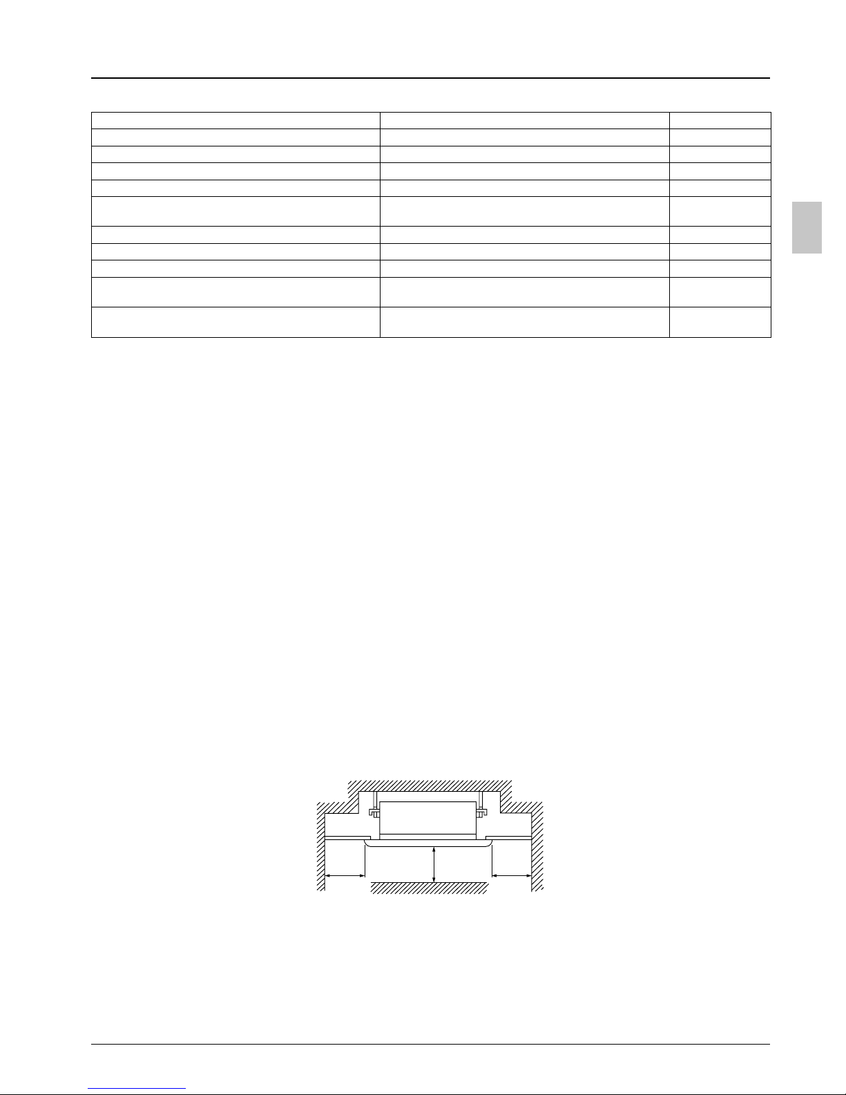
20 cm
or more
100 cm
or more
20 cm
or more
English 4

(2) Ceiling height
D
C
B
A
800
760
710
350
Decoration
panel
Indoor unit
4
Suspension
bolt
Ceiling
opening
This unit can be installed in ceilings up to 3.8 meters high. If the ceiling height exceeds 2.7 meters, however, the connector of terminal board (A2P) must be replaced and an air outlet blocking pad must be
installed. See HIGH CEILING INSTALLATION (P.13).
(3) If you feel there is danger as a result of investigating whether the place you want to install the unit can hold
its weight, reinforce with a board or beam, etc., before installing. (Because installation pitch is recorded on
the paper pattern for installation, check wheter reinforcement will be required or not along with referring to
the paper pattern.)
22 cm
or more
150 cm
or more
2 cm or more
(Suction side)(Discharge side)
4. PREPARATIONS BEFORE INSTALLATION
(1) Relation of ceiling opening to suspension bolt position
Model A B C D
CS-25 · 32 · 40DM1HPK 1110 1150 1200 1240
CS-63DM1HPK 1310 1350 1400 1440
(2) Open a hole in the ceiling for installation. (Case of existing ceiling)
• Use the paper pattern for installation which has been adjusted to the dimensions of the ceiling opening.
• Open a hole in the ceiling for installation at the place the unit is to be installed, and run refrigerant and
drain piping, remote controller cord, and outdoor/indoor transmission wiring to the unit’s piping and wiring hole. (For wiring procedure, refer to “WIRING EXAMPLE AND HOW TO SET THE REMOTE CONTROLLER.” For piping procedure, refer to the attached installation manual of the outdoor unit.)
• After opening a hole in the ceiling, reinforcement of the ceiling frame, etc., may be required to maintain
the levelness of the ceiling and to prevent vibration of the ceiling. For details, consult with your builder
and interior contractor.
〈Set-up example〉
Note) All parts shown in the figure above are field supplied parts.
5 English
Approx.
100 mm
Ceiling slab
Anchor
Wing nut or turnbuckle
Suspension bolt
Ceiling surface
 Loading...