

Page 1
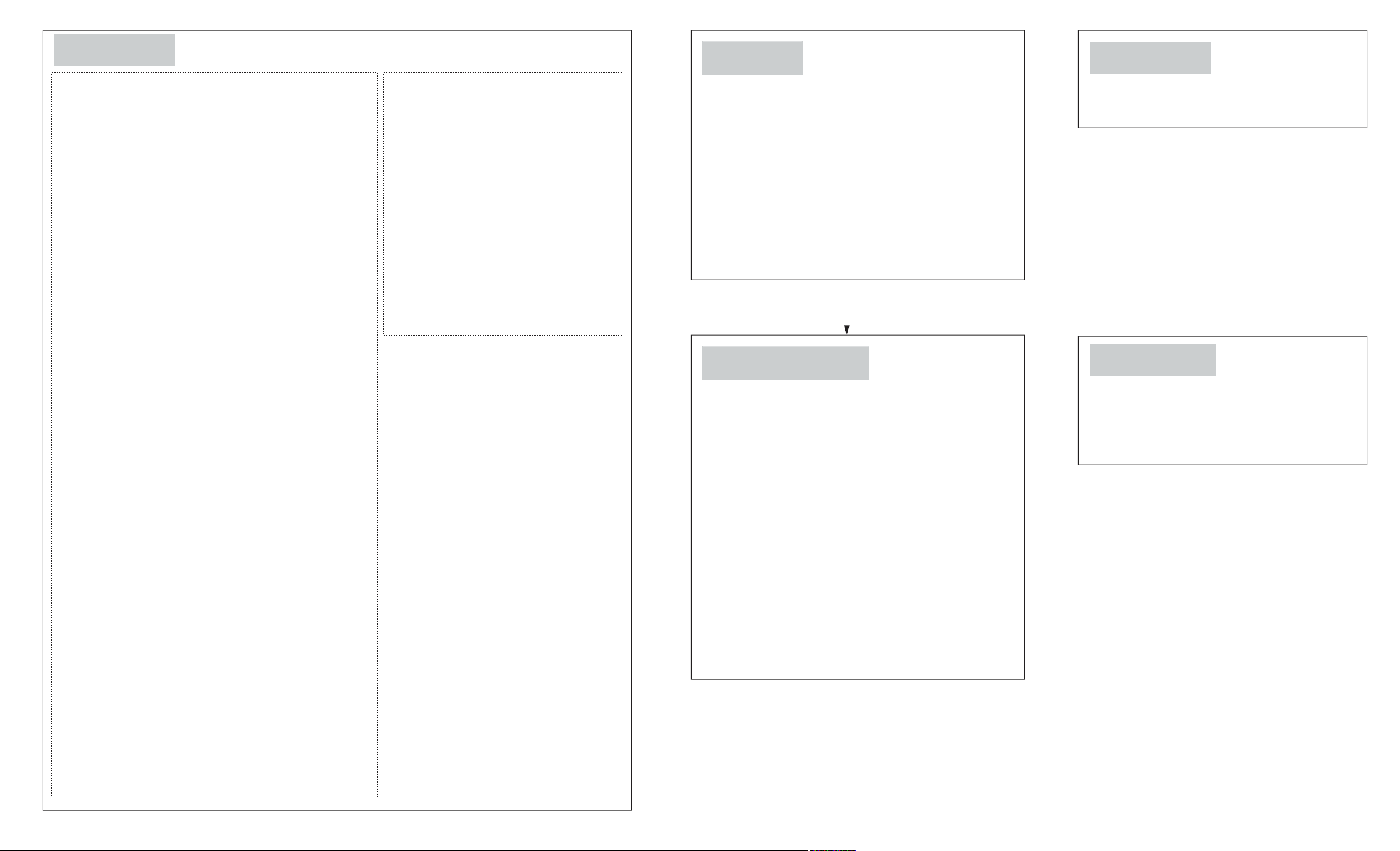
7.2.1 CD Loading Unit
Plunger lever
Step 1: Turn over the unit and install the plunger lever in 90
degree position.
Step 2: Push in the plunger lever.
Step 3: Turn over the unit and install the motor unit properly.
Plunger assembly
Step 4: Install the plunger assembly.
CD loading P.C.B.
Step 5: Install the CD Loading P.C.B.
Step 6: The claws should be latched.
Step 7: Solder the 4 points.
Step 8: Fix it with 4 screws.
Play switch lever
Step 9: Install the play switch lever.
Step 10: Fix the spring below the rib.
Function lever
Step 11: Install the the function lever.
Play gear 1
Step 12: Install the play gear 1.
Function gear and main drive gear
Step 13: Install the main drive gear.
Step 14: Install the function gear.
Gears
Step 15: Install the relay gear 2, switching gear and UD gear 1
respectively.
Step 16: Install the cam gear.Make sure the big hole is fix at the
position (A) at 90 degree.
Step 17: Turn the cam gear anti-clockwise until the big hole
stop at position (B).
Step 18: Install the relay gear 1, relay gear 3, UD gear 2, long
gear and play gear 2 respectively.
Step 19: Install the tray relay gear.
Pulley gear and belt
Step 20: Install the pulley gear followed by the belt.
Change spring
Step 21: Install the change spring.
Pitch plate
Step 22: Install the lock lever 2 in sequence.
Step 23: Install the pitch plate.
Step 24: The 4 claws should be latched properly.
Step 25: Fix it with 3 screws.
Trigger gear
Step 26: Install the trigger gear in sequence.
Step 27: Use the screwdriver to turn the hole
on the UD gear 2 align with the pitch
plate hole.
UD rack R
Step 28: Insert the UD rack R.
Step 29: Push the UD rack R.
UD rack L
Step 30: Insert the UD rack L.
Step 31: Push the claw.
Step 32: Pull the UD rack L.
Tray drive rack
Step 33: Install the tray drive rack.
Play lever B
Step 34: Install the play lever B below the rib.
7.2.2 Disc Trays
Step 1: Tilt and fix the 5 disc trays.
Step 2: Push the 5 disc trays until it stop.
Step 3: Push the tray drive rack until it stop.
Lock lever 1
Step 4: Fix the lock lever 1 onto the pitch plate.
Step 5: Press and hold the claw at the pitch plate then push
the UD rack R.
Step 6: Push the claw and slide the UD rack L.
UD connection lever
Step 7: Install the UD connection lever.
7.2.3 UD Base Assembly
Step 1: Push the traverse slide plate.
Step 2: Install the UD base assembly.
Step 3: Turn UD connection lever anti-clockwise,
the UD base assembly will move downwards.
Step 4: Install the tray lock lever to the mechanism base
and push the tray lock lever with a hand to fix it.
Step 5: Push the disc trays back to the unit.
Trigger Slide Plate
Step 6: Install the trigger slide plate, push forwards and
push the trigger until locked by the claw.
Step 7: Install the OC gear spring followed by the OC gear
assy.
Step 8: Install the open switch lever.
Step 9: Install the gear cover.
Step 10: Install the open lever spring.
Step 11: Install the top cover, fix the top cover hook to
the tray rear stopper.
Step 12: Fixed the top cover, the 2 claws should be latched.
7.2.5 Traverse Unit
Step 1: Turn over the unit and install traverse unit.
Step 2: Push the traverse slide plate to lock the
traverse unit.
7.2.4 CD Loading P.C.B
Step 1: Install the plunger assembly.
Step 2: Install the CD Loading P.C.B.
Step 3: The claw should be latched.
Step 4: Fix it with 4 screws.
Step 5: Solder the 4 points.
Page 2
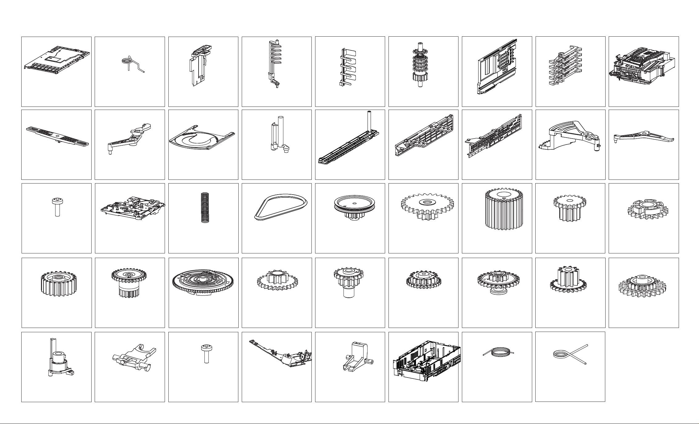
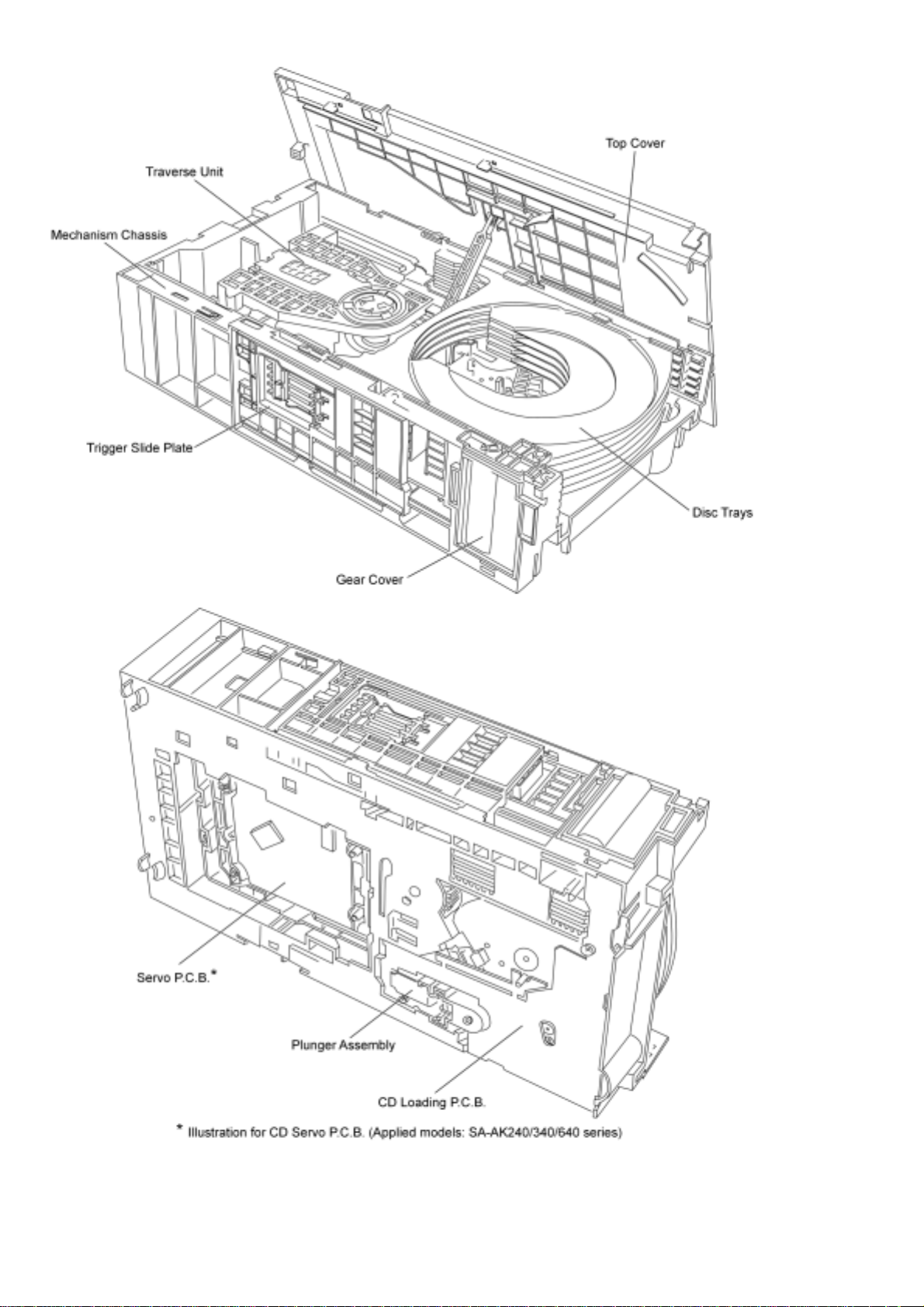
1. Top Cover
2. Open Lever Spring
3. Gear Cover
4. Open Switch Lever
5. OC Gear Spring
6. OC Gear Assy
7. Trigger Slide Plate
8. Tray Lock Lever
9. UD Base Assy
10. UD Connection
Lever
19. Screw
28. Relay Gear 3
11. Lock Lever 1
20. Pitch Plate
29. Relay Gear 1
12. Tray
21. Change Spring
30. Cam Gear
13. Play Lever B
22. Belt
31. UD Gear 1
14. Tray Drive Rack
23. Pulley Gear
32. Switching Gear
15. UD Rack L
24. Tray Relay Gear
33. Relay Gear 2
16.UD Rack R
25. Play Gear 2
34. Function Gear
17. Trigger Gear
26. Long Gear
35. Main Drive Gear
18. Lock Lever 2
27 UD Gear 2
36. Play Gear 1
37. Play Switch Lever
38. Function Lever
39. Screw
40. CD Loading
PCB
41. Plunger Lever
42. Mech Base
43. Play Lever Spring
44. Limit Spring
Page 3
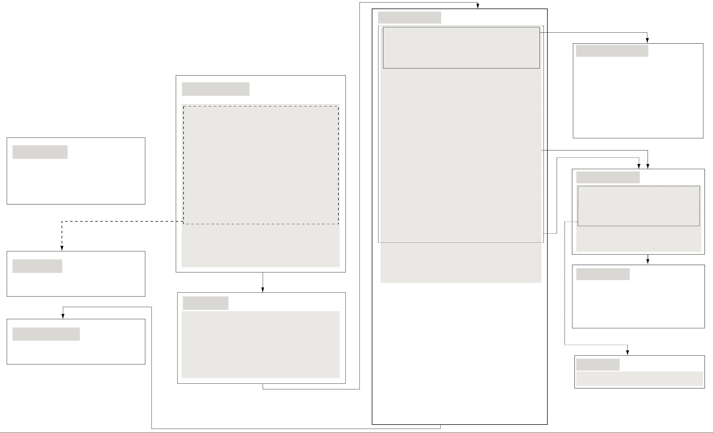
7.1.7 Traverse Unit
Step 1: Press and hold the plunger lever and
rotate the gear until it stop.
Step 2: Push the traverse slide plate to release
the traverse unit.
Step 3: Remove the traverse unit.
7.1.8 Limit Spring
Step 1: Remove the limit spring.
7.1.9 Play Lever Spring
Step 1: Remove the play lever spring.
7.1.1 UD Base Assembly
Step 1: Press the 2 claws downward and push the top
cover backwards and lift up the top cover to
remove it.
Step 2: Release the top cover from the tray rear stopper
and remove the top cover.
Step 3: Remove the open lever spring from the gear cover.
Step 4: Push forwards and remove the gear cover.
Step 5: Remove the open switch lever.
Step 6: Remove the OC gear assy followed by the OC
gear assy.
Step 7: Press the claw, push backwards and remove the
trigger slide plate.
Step 8: Use a minus screwdriver slot into the gap and
push out the tray lock lever.
Step 9: Push the disc trays towards the front.
Step 10: Turn the UD connection lever clockwise.
Step 11: Push the claw and slide the UD rack L.
Step 12: Press and hold the claw at the pitch plate then push
the UD rack R.
Step 13: Remove the UD base assembly.
7.1.2 DiscTrays
UD connection lever
Step 1: Remove the UD connection lever.
Step 2: Push the claw and remove the lock lever 1.
Step 3: Push the tray drive rack to hit the stopper.
Step 4: Push the 5 disc trays until it stop.
Step 5: Lift up slightly and push the 5 disc trays further.
Step 6: Tilt and remove the 5 disc trays.
7.1.3 CD Loading Unit
Play lever B
Step 1: Push the UD rack L forwards.
Step 2: Position the tray drive rack in the center.
Step 3: Push the play lever B and lift up the rib slightly to
remove the play lever B.
Tray drive rack
Step 4: Release the claw and then slide and remove the tray
drive rack.
UD rack L
Step 5: Push the claw.
Step 6: Slide the UD rack L.
Step 7: Lift up the unit.
Step 8: Follow the groove to lift up and remove the UD rack L.
UD rack R
Step 9: Slide the UD rack R until it stop.
Step 10: Press the claw.
Step 11: Continue to slide the UD rack R until it stop.
Step 12: Lift up the UD rack R and slide backwards to stop
at the stopper.
Step 13: Remove the UD rack R.
Trigger gear
Step 14 Turn the trigger gear clockwise and remove it.
Pitch plate
Step 15: Release 3 screws.
Step 16: Remove 4 claws in order followed by detach the pitch
plate.
Lock lever 2
Step 17: Release the claw and pull out the lock lever 2.
Change spring
Step 18: Remove the change spring.
Pulley gear and belt
Step 19: Remove the belt and pull out the pulley gear.
Gears
Step 20: Remove relay gear 1, relay gear 3, UD gear 2, long
gear, play gear 2 and tray gear in order.
Step 21: Remove relay gear 2, switching gear, UD gear 1 in
order.
Cam gear
Step 22: Remove cam gear.
Function gear and main drive gear
Step 23: Remove main drive gear and function gear.
Play gear 1
Step 24: Remove play gear 1.
Function lever
Step 25: Remove the function lever from the ribs.
Step 26: Release the spring from the ribs to remove the play
switch lever.
7.1.10 Pitch Plate Assembly
Step 1: Slide the UD rack L backwards, push
the claw.
Step 2: Slide the UD rack R until it stop.
Step 3: Press the claw.
Step 4: Push the claw, then turn the trigger
gear clockwise and remove it .
Step 5: Remove 3 screws.
Step 6: Release 4 claws in order followed by
detach the pitch plate.
7.1.4 CD Loading P.C.B.
Step 1: Turn over the unit and remove 4 screws
from the CD loading P.C.B.
Step 2: Unsolder the 4 points.
Step 3: Release the claw.
Step 4: Remove the CD Loading P.C.B.
Plunger assembly
Step 5: Remove the plunger assembly by using
a minus screw driver.
7.1.5 Plunger Lever
Step 1: Remove the switching gear.
Step 2: Install the pitch plate.
Step 3: Lift up the plunger lever in 90 degree.
Step 4: Remove the plunger lever in 90 degree
position.
7.1.6 Motor Unit
Step 1: Push the motor unit to remove it.
Page 4

1
2
3
ABCDEFG
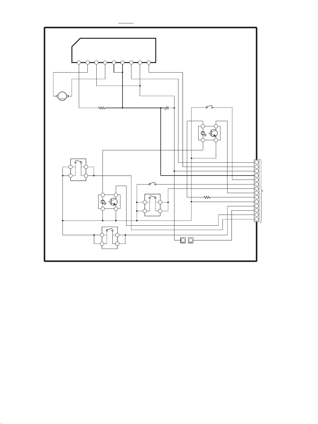
A
CD LOADING P.C.B (REPX0439A)
SOLENOID
SW5
(PLAY)
412
3
4
5
6
7
8
12
34
PH1
(UD SENSOR)
14
13
12
11
10
9
8
7
6
5
4
3
2
1
CN1
9
8
7
6
5
4
3
2
1
IC1
SW4
(TOP)
2143
W7
W2
W1
W3
W5
W4
R2
W6
W8
R1
M1
M
C1
SERVICE JIG
PH2
(CAM SENSOR)
SW3
(HOME)
21
43
SW2
(STOCK)
0458A
PbF
0458A
SW1
(OPEN)
12
34
9
Page 5
SCHEMATIC DIAGRAM - 1
CD LOADING CIRCUIT
C0GAG0000007
LOADING MOTOR DRIVE
VREF
OUT2
RNF
23456
1
M1
M
1
2
SW4
TOP
UD SENSOR
4
3
PH1
SG233
R1
1K
4
3
IC1
OUT1VMVCC
41
32
SW5
PLAY
1
2
: +B SIGNAL LINE
IN1
GND
1
2
IN2
SW2
STOCK
SW1
OPEN
789
4
3
C1
16V100
SW3
HOME
PH2
SG233
CAM SENSOR
R2
390
41
32
CN1
CCW
1
CW
2
PGND
3
VCC_8V
4
HOME_SW
5
ST_SW
6
OPEN_SW
CAM_SENSOR
DGND
PLAY_SW
UD_SENSOR
BOTTOM_SW
SPEED
TO
7
MAIN
8
CIRCUIT
5V
9
10
11
12
13
14
Page 6
http://www.csweb.panasonic-la.com/viewing/ALL/CRS1/SVC/MD0509368C0/doc/MD0509368C0_cvr.xml
ORDER NO. MD0509368C0 A6 Mechanism Unit CRS1
© 2005 Matsushita Electric Industrial Co. Ltd.. All rights reserved. Unauthorized copying and
distribution is a violation of law.
http://www.csweb.panasonic-la.com/viewing/ALL/CRS1/SVC/MD0509368C0/doc/MD0509368C0_cvr.xml13.08.2007 16:16:51
Page 7
http://www.csweb.panasonic-la.com/viewing/ALL/CRS1/SVC/MD0509368C0/doc/MD0509368C0_01.xml
1 Mechanism Overview
http://www.csweb.panasonic-la.com/viewing/ALL/CRS1/SVC/MD0509368C0/doc/MD0509368C0_01.xml13.08.2007 16:17:19
Page 8
http://www.csweb.panasonic-la.com/viewing/ALL/CRS1/SVC/MD0509368C0/doc/cab1.png
http://www.csweb.panasonic-la.com/viewing/ALL/CRS1/SVC/MD0509368C0/doc/cab1.png13.08.2007 16:24:17
Page 9
http://www.csweb.panasonic-la.com/viewing/ALL/CRS1/SVC/MD0509368C0/doc/cab2.png
http://www.csweb.panasonic-la.com/viewing/ALL/CRS1/SVC/MD0509368C0/doc/cab2.png13.08.2007 16:24:33
Page 10
http://www.csweb.panasonic-la.com/viewing/ALL/CRS1/SVC/MD0509368C0/doc/cab3.png
http://www.csweb.panasonic-la.com/viewing/ALL/CRS1/SVC/MD0509368C0/doc/cab3.png13.08.2007 16:24:47
Page 11

http://www.csweb.panasonic-la.com/viewing/ALL/CRS1/SVC/MD0509368C0/doc/MD0509368C0_13.xml
13 Replacement Parts List
Notes:
● Important safety notice:
Components identified by
mark have special characteristics important for safety.
Furthermore, special parts which have purposes of fire-retardant (resistors), high-quality
sound (capacitors), low-noise (resistors), etc. are used.
When replacing any of these components, be sure to use only manufacturers’s specified
parts shown in the parts list.
● Capacitor values are in microfarad (µF) unless specified otherwise, P=Pico-farads(pF);
Farads.
● Resistance values are in ohms, unless specified otherwise, 1K=1,000(ohms).
● The marking (RTL) indicates that the Retention Time is limited for this item. After the
discontinuation of this assembly in production, the item will continue to be available for a
specific period of time. The retention period of availability is dependant on the type of
assembly, and in accordance with the laws governing part and product retention. After the
end of this period, the assembly will no longer be available.
● [M] Indicates in the Remarks columns indicates parts that are supplied by PAVCSG .
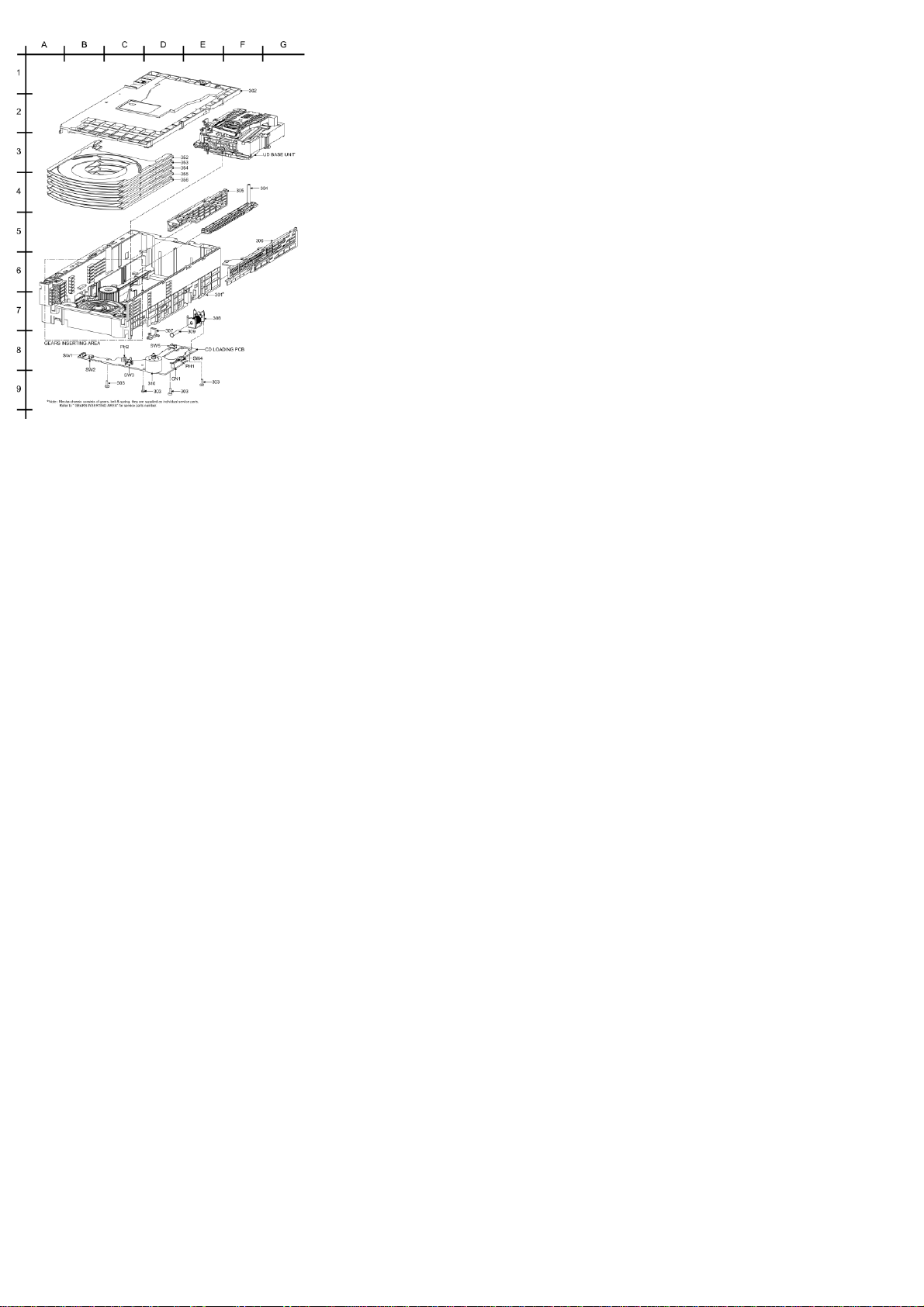
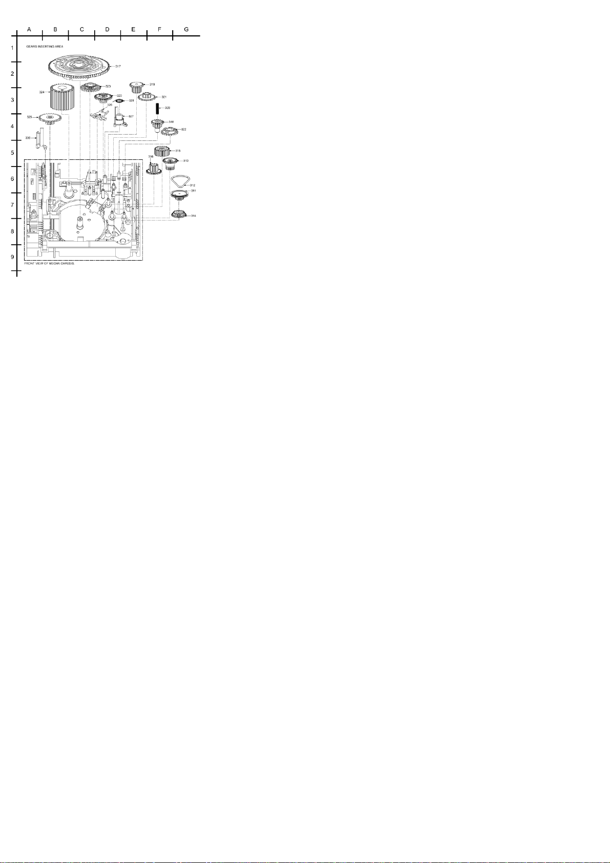
13.1 CD Loading Mechanism Parts List
Ref.
No.
Part No. Part Name & Description Remarks
TRAVERSE DECK
301
RFKJAA340PS MECHA CHASSIS ASS’Y [M]
302
RMLX0029 TOP COVER [M]
303
XTB3+8JFJ SCREW [M]
304
RMMX0008 TRAY DRIVE RACK [M]
305
RMMX0009 UD RACK L [M]
306
RMMX0010-1 UD RACK R [M]
307
RMLX0027 PLUNGER LEVER [M]
http://www.csweb.panasonic-la.com/viewing/ALL/CRS1/SVC/MD0509368C0/doc/MD0509368C0_13.xml (1 •• 4)13.08.2007 16:25:09
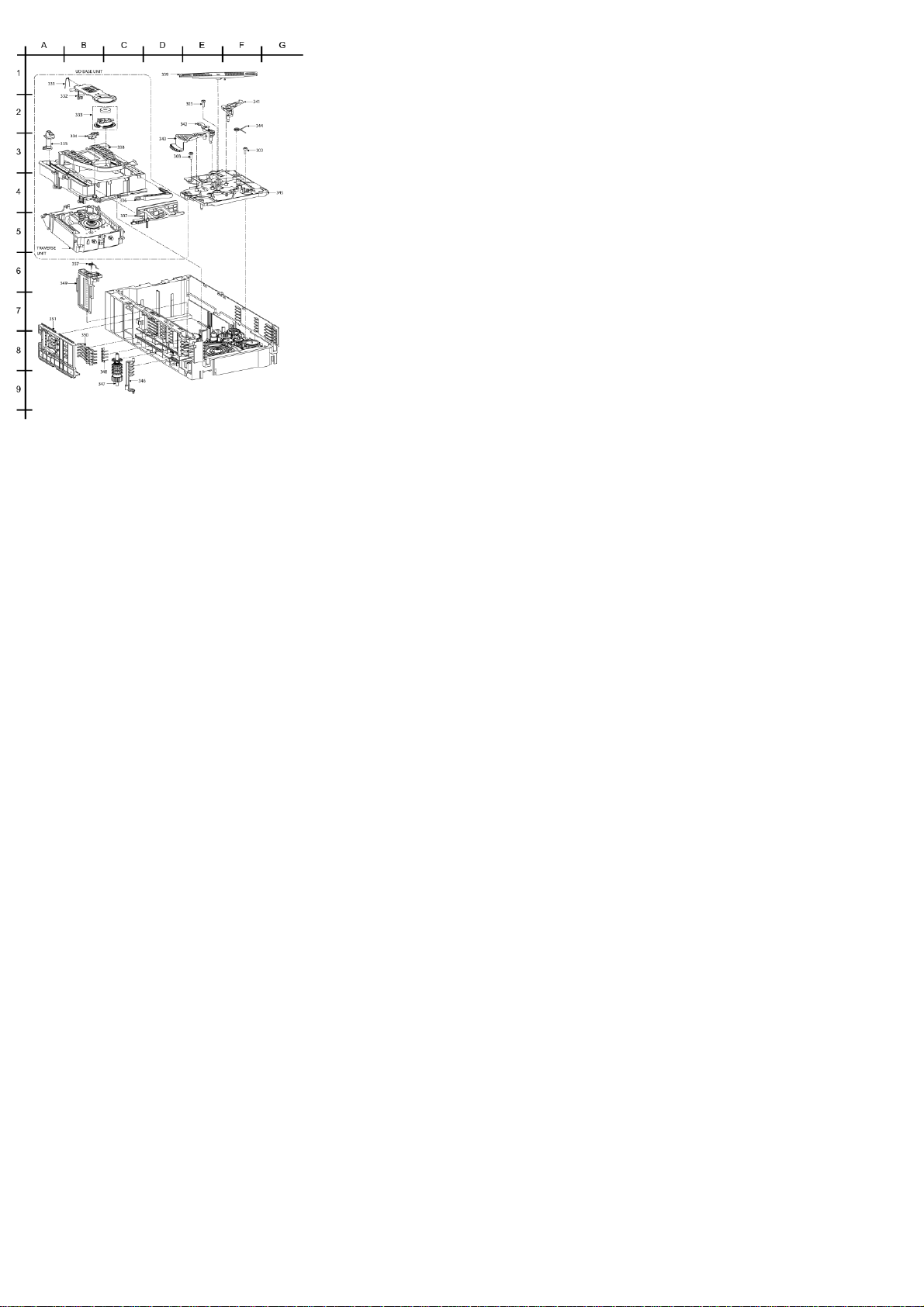
Page 12

http://www.csweb.panasonic-la.com/viewing/ALL/CRS1/SVC/MD0509368C0/doc/MD0509368C0_13.xml
308
RMS0398-1 MOVING CORE [M]
309
RAQX0001-V PLUNGER ASS’Y [M]
310
REMX0001 MOTOR UNIT [M]
311
RDGX0017 PULLEY GEAR [M]
312
RDVX0001 BELT [M]
313
RDGX0018 RELAY GEAR 1 [M]
314
RDGX0019 RELAY GEAR 2 [M]
315
RDGX0038 RELAY GEAR 3 [M]
316
RDGX0037 MAIN DRIVE GEAR [M]
317
RDGX0022 CAM GEAR [M]
318
RDGX0023 SWITCHING GEAR [M]
319
RDGX0024 LONG GEAR [M]
320
RDGX0025 FUNCTION GEAR [M]
321
RDGX0026 UD GEAR 1 [M]
322
RDGX0027 UD GEAR 2 [M]
323
RDGX0028 PLAY GEAR 1 [M]
324
RDGX0029 PLAY GEAR 2 [M]
325
RDGX0031-1 TRAY RELAY GEAR [M]
326
RMLX0024 FUNCTION LEVER [M]
327
RMLX0033 PLAY SWITCH LEVER [M]
328
RMBX0044 PLAY LEVER SPRING [M]
http://www.csweb.panasonic-la.com/viewing/ALL/CRS1/SVC/MD0509368C0/doc/MD0509368C0_13.xml (2 •• 4)13.08.2007 16:25:09
Page 13

http://www.csweb.panasonic-la.com/viewing/ALL/CRS1/SVC/MD0509368C0/doc/MD0509368C0_13.xml
329
RMBX0040 CHANGE GEAR SPRING [M]
330
RMLX0032 PLAY LEVER B [M]
331
RMBX0041
CLAMPER SUPPORT
PLAT
[M]
332
RMMX0011
CLAMPER SUPPORT
PLAT
[M]
333
RXQX0021 CLAMPER UNIT [M]
334
RMLX0031 PLAY LEVER A [M]
335
RMLX0025 TRAY CATCH LEVER [M]
336
RMLX0034 TRAY REAR STOPPER [M]
337
RMMX0007-1 TRV SLIDE PLATE [M]
338
RMRX0057-1 UD BASE [M]
339
RMLX0028 UD CONNECTION LEVER [M]
341
RMLX0036 LOCK LEVER 2 [M]
342
RMLX0035 LOCK LEVER 1 [M]
343
RDGX0030 TRIGGER GEAR [M]
344
RMBX0043 LIMIT SPRING [M]
345
RMQX0132-1 PITCH PLATE [M]
346
RMLX0026 OPEN SW LEVER [M]
347
RXQX0019 OC GEAR UNIT [M]
348
RMCX0031 OC GEAR SPRING [M]
349
RMQX0133-1 GEAR COVER [M]
350
RMLX0030 TRAY LOCK LEVER [M]
http://www.csweb.panasonic-la.com/viewing/ALL/CRS1/SVC/MD0509368C0/doc/MD0509368C0_13.xml (3 •• 4)13.08.2007 16:25:09
Page 14

http://www.csweb.panasonic-la.com/viewing/ALL/CRS1/SVC/MD0509368C0/doc/MD0509368C0_13.xml
351
RMMX0006 TRIGGER SLIDE PLATE [M]
352
RMRX0056A1
TRAY 1 [M]
353
RMRX0056B1
TRAY 2 [M]
354
RMRX0056C1
TRAY 3 [M]
355
RMRX0056D1
TRAY 4 [M]
356
RMRX0056E1
TRAY 5 [M]
357
RMEX0042 OPEN LEVER SPRING [M]
13.2 Electrical Parts List
Ref.
No.
Part No. Part Name & Description Remarks
PRINTED CIRCUIT
BOARD
REPX0439A CD LOADING P.C.B.
[M]
(RTL)
INTEGRATED CIRCUITS
IC1 C0GAG0000007 IC DRIVER [M]
SWITCHES
SW1 RSH1A045-1A SW OPEN [M]
SW2 K0L1BA000117 SW STOCK [M]
SW3 K0L1BA000086 SW HOME [M]
SW4 K0L1BA000078 SW TOP [M]
SW5 K0L1BA000078 SW PLAY [M]
CONNECTORS
CN1 K1MN14A00049 14P FFC CONNECTOR [M]
PH1 B3NAA0000004 PHOTOSENSOR [M]
PH2 B3NAA0000004 PHOTOSENSOR [M]
RESISTORS
R1 D0AE102JA048 1K 1/4W [M]
R2 D0AE101JA048 100 1/4W [M]
CAPACITORS
C1 ECEA1CKA101B 100 16V [M]
FLE0509D/E/J/N/S/A
http://www.csweb.panasonic-la.com/viewing/ALL/CRS1/SVC/MD0509368C0/doc/MD0509368C0_13.xml (4 •• 4)13.08.2007 16:25:09
Page 15
http://www.csweb.panasonic-la.com/viewing/ALL/CRS1/SVC/MD0509368C0/doc/MD0509368C0_02.xml
2 Mechanism Drive Unit 2.1 Tray Open/Close and Multi-Discs Change operations
2.1.1 Description of
tray open/close and multi-discs change operations
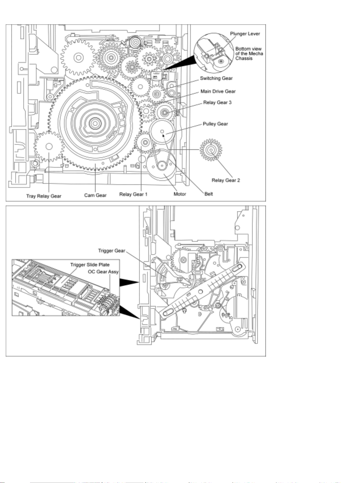
1. The motor turns in the clockwise direction and the rotation is transmitted via the belt, the
pulley gear also turns clockwise.
2. The relay gear 1 turns counterclockwise.
3. The relay gear 2 turns clockwise.
4. The relay gear 3 turns counterclockwise.
5. The switching gear at down position turns clockwise (up/down position functioned by the
plunger lever).
6. The main drive gear turns counterclockwise.
http://www.csweb.panasonic-la.com/viewing/ALL/CRS1/SVC/MD0509368C0/doc/MD0509368C0_02.xml (1 •• 4)13.08.2007 16:17:36
Page 16
http://www.csweb.panasonic-la.com/viewing/ALL/CRS1/SVC/MD0509368C0/doc/MD0509368C0_02.xml
7. The cam gear turns clockwise, which is engaged with the trigger gear and slide plate, are
driven, causes the tray lock lever unlock.
8. The tray relay gear turns counterclockwise, which is engaged with the OC assy, is driven.
9. The movement of the OC assy releases the disc trays.
(The operation of the disc trays closed is the opposite of that for opening of disc trays.)
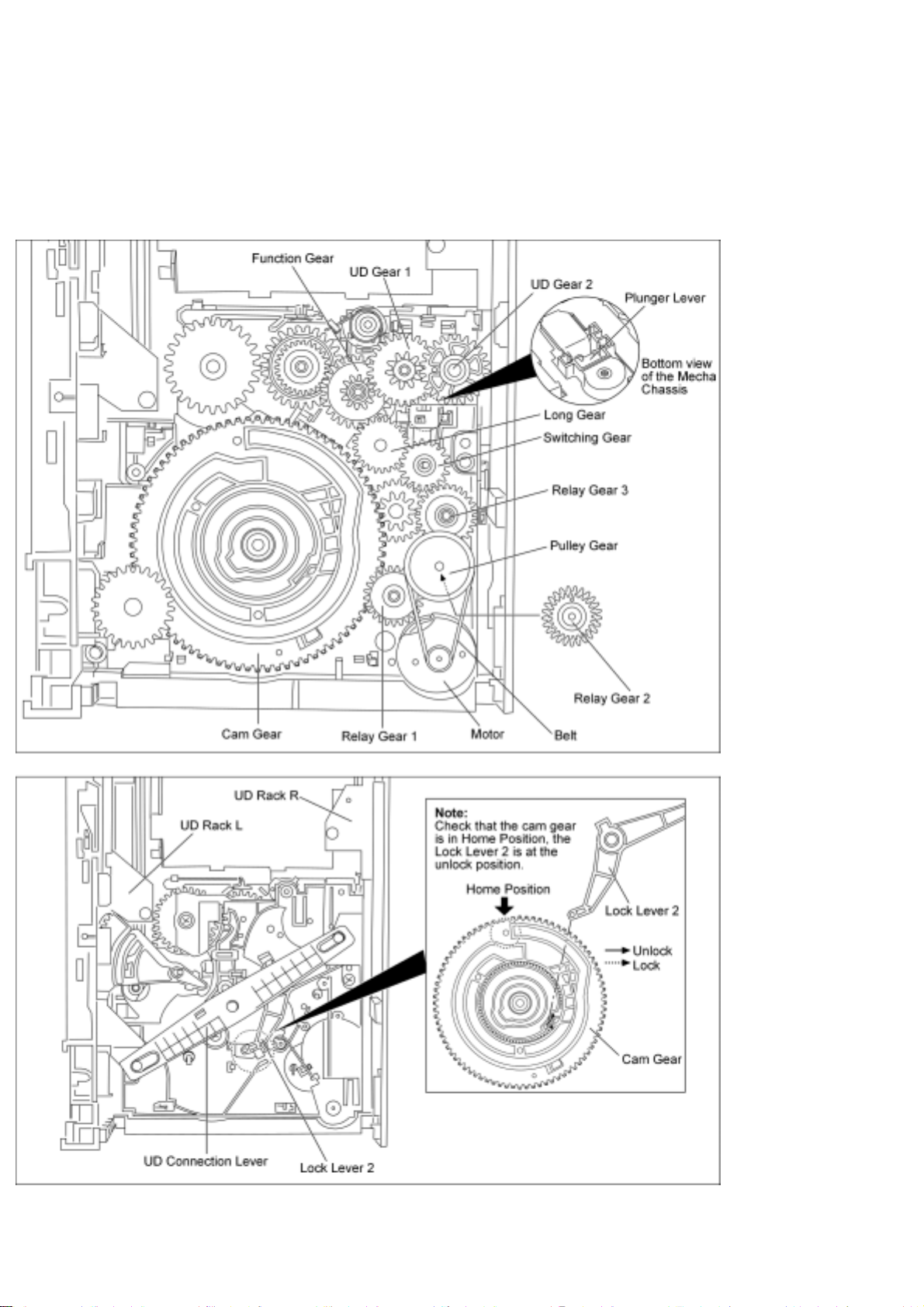
2.2 Disc Selection operation
2.2.1 Description of
disc selection operation Note: Check that the cam gear is in “HOME” position.
http://www.csweb.panasonic-la.com/viewing/ALL/CRS1/SVC/MD0509368C0/doc/MD0509368C0_02.xml (2 •• 4)13.08.2007 16:17:36
Page 17
http://www.csweb.panasonic-la.com/viewing/ALL/CRS1/SVC/MD0509368C0/doc/MD0509368C0_02.xml
1. The motor turns in the clockwise direction and the rotation is transmitted via the belt, the
pulley gear also turns clockwise.
2. The relay gear 1 turns counterclockwise.
3. The relay gear 2 turns clockwise.
4. The relay gear 3 turns counterclockwise..
5. The switching gear move up turns clockwise (up/down position functioned by the plunger
lever).
6. The long gear turns counterclockwise.
7. The function gear moved up turns clockwise.
8. The UD gear 1 turns counterclockwise.
9. The UD gear 2 turns clockwise engaged with the UD rack R drives the UD connection
lever turns clockwise, UD rack L, is driven to move the traverse deck assembly up.
(The operation of the traverse deck assembly down is the opposite of that for the traverse deck
assembly up.)
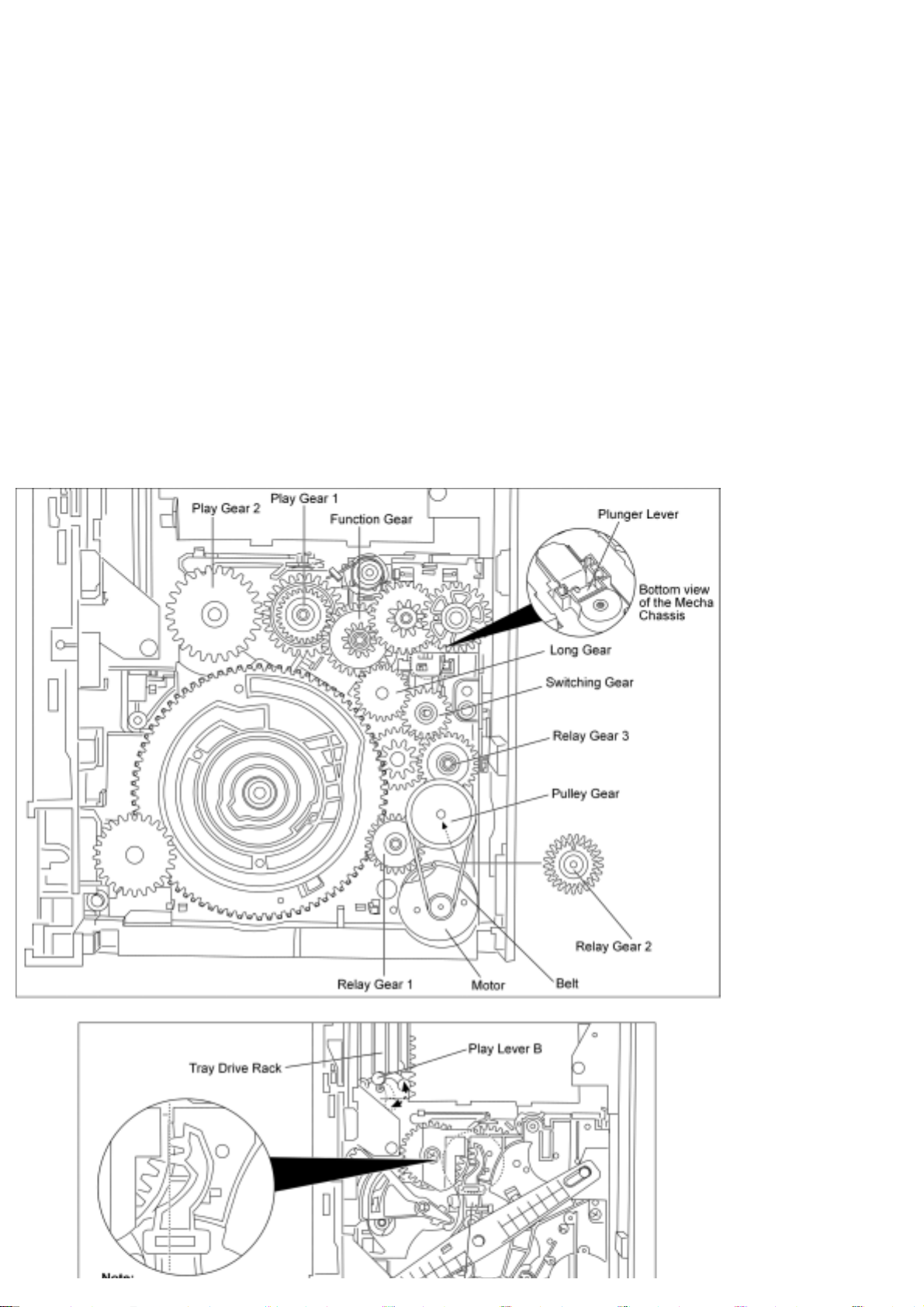
2.3 Play/Stop operation
http://www.csweb.panasonic-la.com/viewing/ALL/CRS1/SVC/MD0509368C0/doc/MD0509368C0_02.xml (3 •• 4)13.08.2007 16:17:36
Page 18

http://www.csweb.panasonic-la.com/viewing/ALL/CRS1/SVC/MD0509368C0/doc/MD0509368C0_02.xml
2.3.1 Description of
play/stop operation Note: Check that the Lock Lever 1 is unlock.
1. The motor turns in the clockwise direction and the rotation is transmitted via the belt, the
pulley gear also turns clockwise.
2. The relay gear 1 turns counterclockwise.
3. The relay gear 2 turns clockwise.
4. The relay gear 3 turns counterclockwise.
5. The switching gear move up turns clockwise (up/down position functioned by the plunger
lever).
6. The long gear turns counterclockwise.
7. The function gear move down turns clockwise.
8. The play gear 1 turns counterclockwise.
9. The play gear 2 turns clockwise engaged with the tray drive rack and tray catch lever to
push in the disc trays.
10. Play lever B engaged with the traverse deck assembly’s play lever A, causes slide plate
move towards to the play position.
http://www.csweb.panasonic-la.com/viewing/ALL/CRS1/SVC/MD0509368C0/doc/MD0509368C0_02.xml (4 •• 4)13.08.2007 16:17:36
Page 19
http://www.csweb.panasonic-la.com/viewing/ALL/CRS1/SVC/MD0509368C0/doc/MD0509368C0_03.xml
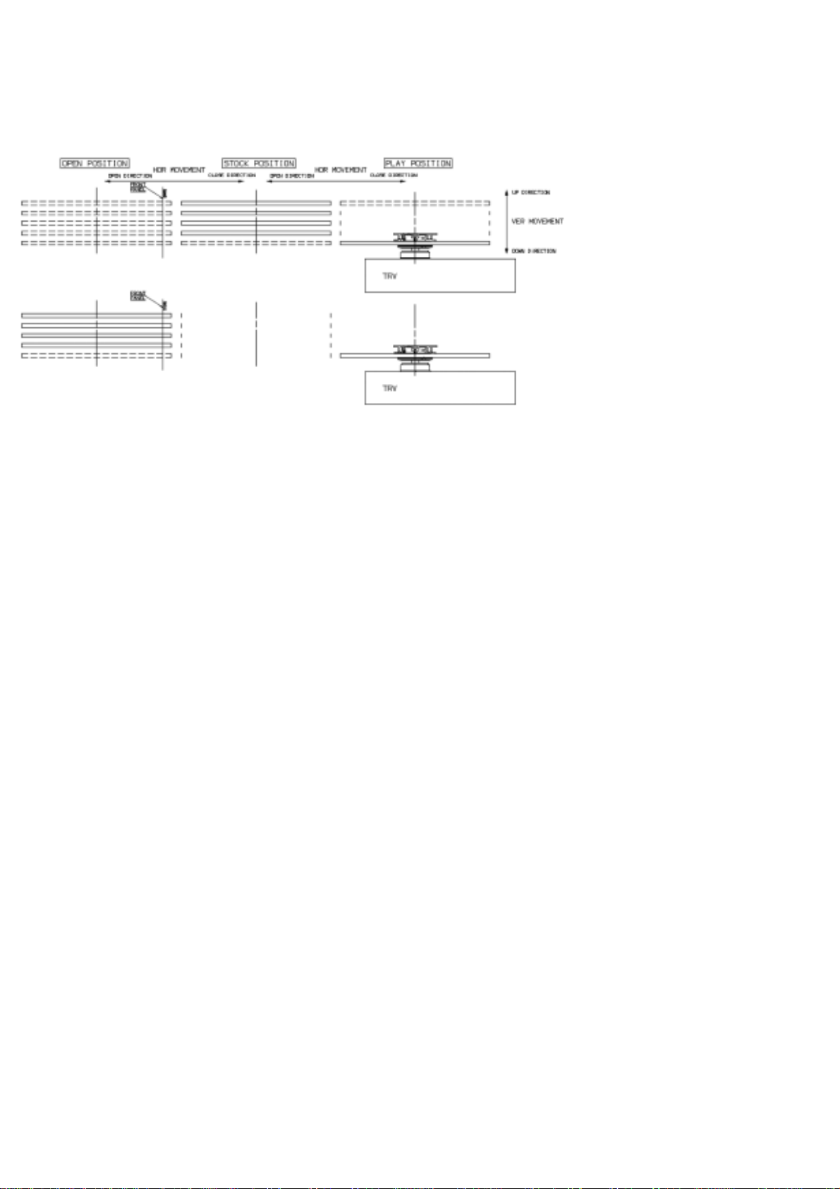
3 Mechanism Operation Description 3.1 General Feature
● This is a five disc changer mechanism for CD/DVD. The outline figure is shown below.
● The mechanism has "CHANGE WHILE PLAY" function. It open other trays for disc
exchanging while one tray is at PLAY position performing recording or reproducing.
● The mechanism can quickly change all trays with "CHANGE ALL" function. All trays can be
move to OPEN position with one operation.
● There is no sensor to indicate presence of disc on any tray.
3.2 Hardware composition
● Below is the hardware components of the mechanism
Name Function
Open Switch (OPEN-SW)
The switch is used to detect normal tray opening
The switch is used for detect tray being manually push/trigger when full open
Home Switch (HOME-SW) Is used to detect cam gear home position
Close Sensor (CLOSE-
SENSOR)
Used for normal single tray closing
Used to detect cam gear rotate to Play Driving position
Play Switch (PLAY-SW) Detect TRV clamping complete position
Stocking Switch (STOCK-SW) Detect tray completely transfer for play position to stocking positi
UD Sensor (UD-SENSOR) Detect TRV vertical movement position
Top Switch (TOP-SW) Detect a default position of TRV vertical movement position
Driver IC To drive Motor
Motor Main driving source for changer
Plunger
Switching the driving source from motor to:
1. Tray open/close
2. Drive tray to play/stock position and TRV vertical movemen
3.3 Mechanism Operation
http://www.csweb.panasonic-la.com/viewing/ALL/CRS1/SVC/MD0509368C0/doc/MD0509368C0_03.xml (1 •• 26)13.08.2007 16:17:56
Page 20

http://www.csweb.panasonic-la.com/viewing/ALL/CRS1/SVC/MD0509368C0/doc/MD0509368C0_03.xml
● This mechanism has the following state:
1. Driving of a tray to open/close
2. Up/down operation of a traverse performs a state changes of tray.
By using the plunger to lift/release of a switching gear, and the cam gear to lift/release the
function gear the motor can be link to several gear trains to perform various operations.
● The functions that can be perform in this mechanism are described as below:
Note: * represent tray number (from 1 ~ 5)
Condition Explanation
Open current playing
tray
The state to change current playing disc. All tray will be open at once and current tray at
PLAY position will be expose.
Open All
The state where all trays being driven to OPEN position. The disc can be taken in or out
from tray to tray by close tray one by one from top to bottom.
Stock The state where the trays are stored in STOCK position
Play
The state where one of the tray 5 trays is being driven to PLAY position and clamped by
traverse unit
Play & Open Tray-*
The state where one of the tray is in playing position performing recording or
reproducing, other trays can be used (OPEN position) for disc exchanging without
stopping the recording or reproducing process.
Change
The state when one of the opened tray being driven from OPEN position to STOCK
position and other opened trays remain still at OPEN position.
Close All
The state where all open trays will being driven from OPEN position to STOCK
position, one by one from top to bottom
● Logics of motor control:
Notes :
CW/CCW : Motor direction control (CW : clockwise, CCW : Anti-clockwise)
Plunger : Solenoid Control (H : ON = Activation)
Action CW CCW Plunger
Tray Opening H L L
Tray Closing L H L
Cam move from Home Position to Play Driving
Position
H L L
Cam move from Play Driving Position to Home
Position
L H L
Drive tray to PLAY position H L H
Drive tray to STOCK position L H H
UD base moving upward H L H
UD base moving downward L H H
● Cam gear in the mechanism use for opening/closing of trays and lifting a function gear to link
http://www.csweb.panasonic-la.com/viewing/ALL/CRS1/SVC/MD0509368C0/doc/MD0509368C0_03.xml (2 •• 26)13.08.2007 16:17:56
Page 21
http://www.csweb.panasonic-la.com/viewing/ALL/CRS1/SVC/MD0509368C0/doc/MD0509368C0_03.xml
to gear train that drive UD base moving up/down. When cam gear is being driven to play
driving position, the function gear will be bring down to link the gear train that drive tray to
and from STOCK position and PLAY position. Below are the relation between mechanism
function and cam gear movement and position
Motor
Direction
Plunger
Unit
Cam gear movement/position Function
CW Release
Home SW → rotate CW
Trays Open
CCW Release
Rotate CCW → Home SW
Trays Close
CW Release
Home SW → close sensor 1st L-H signal
Cam gear move from Home Position
to Play Driving Posi
CCW Release
Close sensor 1st (H → L) signal → Home
SW
Cam gear move from Play Driving
Position to Home Position
CW Up Cam Stop at Home Position UD base moving from bottom to top
CCW Up Cam Stop at Home Position UD base moving from top to bottom
CW Up Cam Stop at Play Driving Position
Tray move from STOCK to PLAY
position
CCW Up Cam Stop at Play Driving Position
Tray move from PLAY position to
STOCK Position
● Cam gear rotation direction, switch and state changes is show in figure below:
● The movement of UD base (vertical up/down) and driving of tray(s) between STOCK
position and PLAY position is only enable when plunger ON (lift up the switching gear to
link driving source to the both gear train). Only one gear train can be driven at one time, the
selection of either gear train is depending on cam gear position. Below are figure showing the
operation of motor driving direction and its function carry out.
Cam Gear
Motor Home Position (UD Driving Position)
Play Driving
Position
CW
UD base move upwards direction 5→1 Stock → Play
CCW
UD base move downwards direction
1→5
Play → Stock
● For driving UD base up/down the cam gear must be at the home position (UD driving
position) and plunger need to be activated, the switch and state change is as figure below:
http://www.csweb.panasonic-la.com/viewing/ALL/CRS1/SVC/MD0509368C0/doc/MD0509368C0_03.xml (3 •• 26)13.08.2007 16:17:56
Page 22
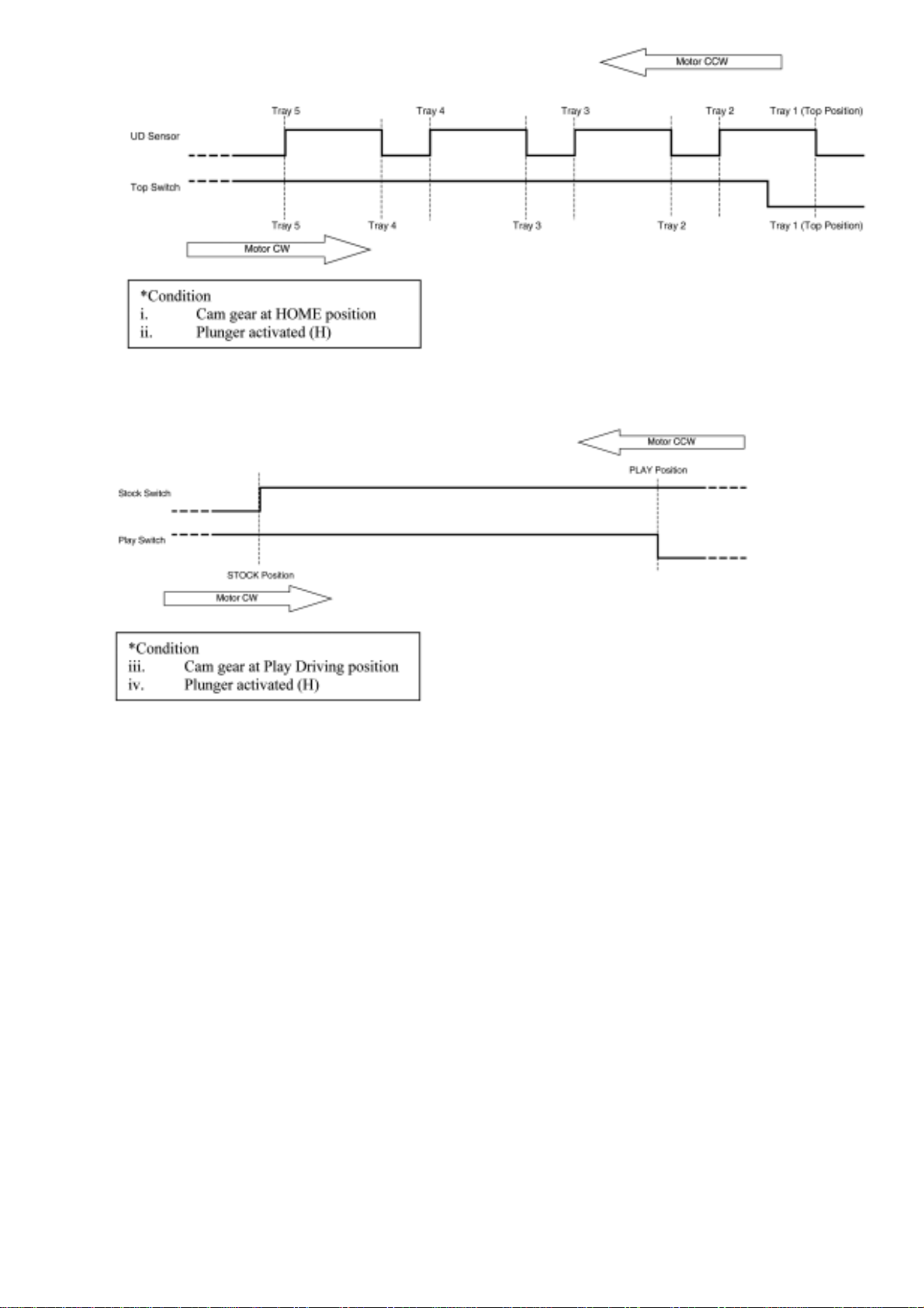
http://www.csweb.panasonic-la.com/viewing/ALL/CRS1/SVC/MD0509368C0/doc/MD0509368C0_03.xml
● To drive the tray(s) between STOCK/PLAY position, cam gear must be at the play driving
position and plunger need to be activated, the switch and state change is as figure below:
● The mechanism tray opening and closing is cycle process. It is able to open all trays in
STOCK position while one of the tray is in PLAY position. The closing can be done one by
one or close all at once depend on the user instruction. Below show the tray opening and
closing flow.
http://www.csweb.panasonic-la.com/viewing/ALL/CRS1/SVC/MD0509368C0/doc/MD0509368C0_03.xml (4 •• 26)13.08.2007 16:17:56
Page 23

http://www.csweb.panasonic-la.com/viewing/ALL/CRS1/SVC/MD0509368C0/doc/MD0509368C0_03.xml
3.4 Switches Chattering Check
● Each input shall perform chattering check processing.
OPEN-SW
2ms Periodic sampling. It logic-decides by continuation same 5
times.
PLAY-SW
2ms Periodic sampling. It logic-decides by continuation same 5
times.
STOCK-SW
2ms Periodic sampling. It logic-decides by continuation same 5
times.
TOP-SW
2ms Periodic sampling. It logic-decides by continuation same 5
times.
HOME-SW
2ms Periodic sampling. It logic-decides by continuation same 5
times.
UD-SENSOR
2ms Periodic sampling. It logic-decides by continuation same 5
times.
CLOSESENSOR
2ms Periodic sampling. It logic-decides by continuation same 5
times.
3.5 Motor Movement Control
Condition
Motor
CW CCW
Free L L
Rotate CW H L
Rotate
CCW
L H
Short Brake H H
http://www.csweb.panasonic-la.com/viewing/ALL/CRS1/SVC/MD0509368C0/doc/MD0509368C0_03.xml (5 •• 26)13.08.2007 16:17:56
Page 24

http://www.csweb.panasonic-la.com/viewing/ALL/CRS1/SVC/MD0509368C0/doc/MD0509368C0_03.xml
3.6 Plunger Timing Chart
● Plunger is use for pulling the lever that a switching gear is sit on the lever. When current
supply to the plunger to pulling (kick) switching gear, it will be lift up to engage to 1 st gear
train. When current supply to plunger is cut off (release), switching gear will be bring done
by gravity force and mechanical coil spring on top of it. Plunger use for connect the driving
source from motor to 2 different gear train in the mechanism, the functions of the gear trains
are as below:
1. Tray open/close
2. Drive tray to play/stock position and TRV vertical movement
● The plunger movement is define as below:
Kick = H, Release= L
● Each time during plunger activation time (Kick/Release), the motor shall perform a short time
CW and CCW rotation for release the gear side force and ensure complete gear to gear
engagement.
● The basic concept of the motor rotation sequence (CW or CCW) is base on the initial and
final motor rotating direction. The direction should be opposite to the initial and final motor
driving direction in order to:
1. To release the gear teeth side force
2. To release mechanism belt tension
3. To ensure switching gear disengage or engage into other gear•s teeth
● Summary of the type of motor short rotation direction is as below:
Motor
Direction
Initial
Short Rotate Direction
Final
Switching
Mode
1 st 2 nd 3 rd
Plunger Kick
CW
CCW CW CCW CW A
CCW CW - CCW B
CCW
CW CCW - CW C
CW CCW CW CCW D
Plunger
Release
CW
CCW CW CCW CW E
CCW CW - CCW F
CCW
CW CCW - CW G
CW CCW CW CCW H
● Below are the timing charts of plunger activation time.
http://www.csweb.panasonic-la.com/viewing/ALL/CRS1/SVC/MD0509368C0/doc/MD0509368C0_03.xml (6 •• 26)13.08.2007 16:17:56
Page 25

http://www.csweb.panasonic-la.com/viewing/ALL/CRS1/SVC/MD0509368C0/doc/MD0509368C0_03.xml
● As the plunger only activate at 2 position of cam gear. The plunger mode summary as below:
Switching
Position
Initial Motor Direction
Switching
Mode
Initial Motor Direction Function
http://www.csweb.panasonic-la.com/viewing/ALL/CRS1/SVC/MD0509368C0/doc/MD0509368C0_03.xml (7 •• 26)13.08.2007 16:17:56
Page 26

http://www.csweb.panasonic-la.com/viewing/ALL/CRS1/SVC/MD0509368C0/doc/MD0509368C0_03.xml
Home
Position
Cam gear rotate CCW to
HOME
Motor : CCW
C
UD base move from bottom
to top
Motor : CW
Tray selection from bottom to
top
Cam gear rotate CCW to
HOME
Motor : CCW
D
UD base move from top to
bottom
Motor : CCW
Tray selection from top to
bottom
UD base move from bottom
to top
Motor : CW
E
Cam gear rotate CW from
HOME to Play Driving
Position. Motor : CW
After tray selection, cam gear
rotate to Play Driving
Position
UD base move from top to
bottom
Motor : CCW
G
Cam gear rotate CW from
HOME to Play Driving
Position. Motor : CW
After tray selection, cam gear
rotate to Play Driving
Position
Play
Driving
Position
Cam gear rotate CW from
HOME to Play Driving
Position. Motor : CW
A
Drive tray from STOCK
position to PLAY position.
Motor : CW
Load tray to Play
Cam gear rotate CW from
HOME to Play Driving
Position. Motor : CW
B
Drive tray from PLAY
position to STOCK position.
Motor : CCW
Unload tray from Play to
Stock
Drive tray from STOCK
position to PLAY position.
Motor : CW
F
Cam gear rotate CCW from
Play Driving Position to
HOME. Motor : CCW
After load tray to Play, cam
gear return to HOME
Drive tray from PLAY
position to STOCK position.
Motor : CCW
H
Cam gear rotate CCW from
Play Driving Position to
HOME. Motor : CCW
After unload tray from Play,
cam gear return to HOME
Drive tray from PLAY
position to STOCK position.
Motor : CCW
G
Cam gear rotate CW from
until trays full open. Motor :
CW
Open trays while one tray
Play
● Switching mode G is used during initialization to ensure that the switching gear is at the
release (down) condition before the initialization process begins.
3.7 Initialization of Mechanism Unit.
● Mechanism Initialization -- This mechanism is designed to operate & set to a pre-defined
position to prevent malfunction when unavoidable circumstances happen. For examples: user
mis-handling during transportaion or abnormal user operations.This is comply to the product
shipping reliability standards.
● Mechanism is initialized when the mechanism controller is unable to detect the present
condition/state of mechanism. For example, when the microcomputer carries out a cold start.
(In complete unit)
http://www.csweb.panasonic-la.com/viewing/ALL/CRS1/SVC/MD0509368C0/doc/MD0509368C0_03.xml (8 •• 26)13.08.2007 16:17:56
Page 27

http://www.csweb.panasonic-la.com/viewing/ALL/CRS1/SVC/MD0509368C0/doc/MD0509368C0_03.xml
● Once the initialization process is completed, the mechanism unit is set to this condition:-
1. Tray 1 is at PLAY position (Top tray)
2. The traverse unit is at clamping condition (PLAY SW-L)
3. All the remaining trays are in STOCK Position (Trays 2 ~ 5 )
4. Plunger lever at release condition
5. Cam gear is at Home position ( HOME SW-L)
6. Motor is free (CW-L, CCW-L)
Note: This is same as shipment condition. (In complete unit)
● Below is the flow chart of the initialization process:-
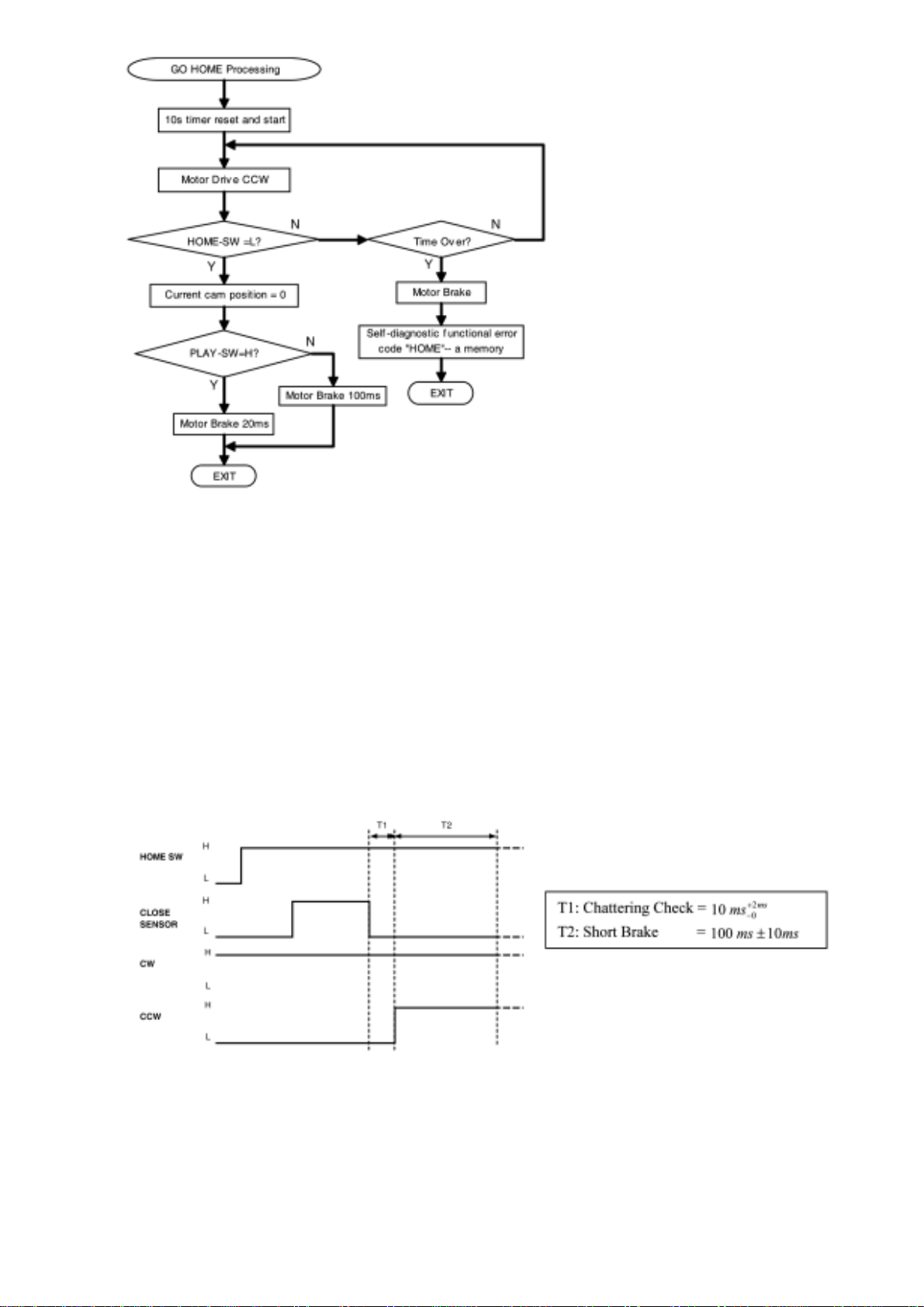
3.8 Mechanism “HOME” position
● Mechanism HOME position is a starting position for few functions, such as below:
1. Load tray from STOCK position to PLAY position
2. Unload tray from PLAY position to STOCK position
3. Open trays
4. Driving UD base up/down
http://www.csweb.panasonic-la.com/viewing/ALL/CRS1/SVC/MD0509368C0/doc/MD0509368C0_03.xml (9 •• 26)13.08.2007 16:17:56
Page 28
http://www.csweb.panasonic-la.com/viewing/ALL/CRS1/SVC/MD0509368C0/doc/MD0509368C0_03.xml
● Besides this, it will always return to “HOME” position after performing below functions:
1. After tray completely clamped by Traverse unit
2. Closing All trays
3. Closing tray 5
4. After completely the UD base movement
● There are 2 type of mode to go to HOME position.
Mode 1 is to go to HOME position and motor brake and stay at HOME position, motor need
longer brake time for reduce overrun of mechanical parts.
For Mode 2, after mechanism go to HOME position, motor immediately rotate reverse
direction to go do loading/unloading processing, shorter brake time necessary to reduce the
total mechanism operation time.
The table below is types of "GO HOME" mode and operation that use it.
GO HOME MODE 1 GO HOME MODE 2
1. After loading tray to PLAY position
1. After closing all trays (no tray at PLAY
position)
2. After unloading tray to STOCK position
3. After closing all trays (one tray at PLAY
position)
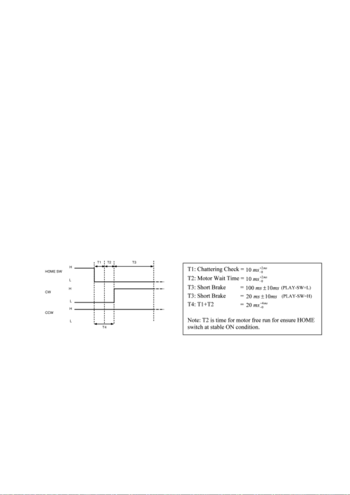
● The timing chart for the mechanism to set to “HOME” position is illustrated as below.
● Below is the flow chart for the mechanism to set to “HOME” position.
http://www.csweb.panasonic-la.com/viewing/ALL/CRS1/SVC/MD0509368C0/doc/MD0509368C0_03.xml (10 •• 26)13.08.2007 16:17:56
Page 29
http://www.csweb.panasonic-la.com/viewing/ALL/CRS1/SVC/MD0509368C0/doc/MD0509368C0_03.xml
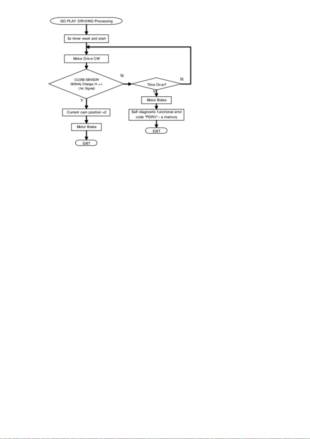
3.9 Mechanism “Play Driving” position
● Play driving position is a position driving source linkage to drive the tray(s) between STOCK
position and PLAY position (load and unload of tray). Cam gear will rotate to this position
from HOME position, and after the completion of clamping process will back to HOME
position.
For Go to Play Driving position, cam gear move from HOME position, motor brake after
detect 1 st time CLOSE sensor signal change from H→L
● Below is the flow chart for the mechanism to set PLAY DRIVING position.
http://www.csweb.panasonic-la.com/viewing/ALL/CRS1/SVC/MD0509368C0/doc/MD0509368C0_03.xml (11 •• 26)13.08.2007 16:17:56
Page 30
http://www.csweb.panasonic-la.com/viewing/ALL/CRS1/SVC/MD0509368C0/doc/MD0509368C0_03.xml
3.10 Trays Operation 3.10.1 Tray ‘Open’ Operation
● Changer mechanisms are required to open trays to load a disc. This mechanism features an
"All Open" or "Change all one by one" function for quick & easy disc change. There are 3
kinds of "Tray Open" conditions.
1. All trays open
Occurs when OPEN/CLOSE button is pressed, playing tray will be driven to
STOCK position and all trays will driven to OPEN position. All trays will remain
open until "DISC CHANGE" or "OPEN/CLOSE" is pressed. When "DISC
CHANGE" is pressed, the upper most tray will close while "OPEN/CLOSE" is
close all trays.
2. Open selected tray while one tray at PLAY position
Occurs when specify tray is selected to be opened while one tray is at PLAY
position. This operation never disturbs the playing disc operation and allow user
to change desire disc on specific tray.
3. Direct open playing tray
Occurs only when the user selects to open playing tray. Tray at PLAY position
will stop recording/reproducing process and being driven to STOCK position.
This will follow by driven all trays to OPEN position and trays closing until the
previous playing tray expose for disc changing.Example: User press "DISC
CHANGE" + "DISC 3". Mechanism opens all the trays, then closes trays 1 & 2
respectively exposing the tray 3.
● The timing chart for both positions is the same, motor rotate CW direction, until OPEN SW
changing signal H→ L → H, motor need to continue run for 45ms.
http://www.csweb.panasonic-la.com/viewing/ALL/CRS1/SVC/MD0509368C0/doc/MD0509368C0_03.xml (12 •• 26)13.08.2007 16:17:56
Page 31

http://www.csweb.panasonic-la.com/viewing/ALL/CRS1/SVC/MD0509368C0/doc/MD0509368C0_03.xml
● Motor free at the end of tray open, this is for enable the tray to be manually pushing by user.
● Below is the timing chart for tray opening.
● For all type of trays opening, either 4 trays (open remaining) or 5 trays (all open) will be set
to OPEN position.
3.10.2 Tray Closing Operation
● The following action is tray closing. For this mechanism, there are 3 types of trays closing
also.
1. All trays close
When user press "OPEN/CLOSE" after trays open, all trays (at any condition)
will being driven to STOCK position.
2. Auto Tray Close
This closing operation is an internal operation in the mechanism. This operation
completes the open selected tray function. Mechanism uses this operation to drive
trays that cover top surface of desire tray to STOCK position and then expose the
selected tray for user to do disc exchanging.
3. Change
When user press "CHANGE", one tray will be driven to STOCK position. This
operation is for changing disc one by one from top to bottom. The operation each
time will only drive the upper most tray to STOCK position, it can be only being
interrupt by "OPEN/CLOSE". If the "CHANGE" being pressed during one tray is
http://www.csweb.panasonic-la.com/viewing/ALL/CRS1/SVC/MD0509368C0/doc/MD0509368C0_03.xml (13 •• 26)13.08.2007 16:17:56
Page 32

http://www.csweb.panasonic-la.com/viewing/ALL/CRS1/SVC/MD0509368C0/doc/MD0509368C0_03.xml
closing, mechanism will close the second tray immediately after 1st tray. The
number of tray will be closed equal to number time of "CHANGE button" being
pressed.
● All trays close can occurs anytime when there is tray at open condition. The all trays close
processing is used when mechanism carry out the function as:
1. Close Tray 5
2. Close Tray 4 while tray 5 is in PLAY position
3. User press OPEN/CLOSE to instruct all trays close.
● Mechanism will close all the trays by rotating cam gear at CCW direction until detect HOME
position
● Below is the timing chart for tray close (until detect HOME position).
● Table below explain the function of open selected tray while one tray at PLAY position. This
table indicated the possible tray at playing trays. For opened tray, all trays will be open except
the tray at PLAY position. Trays will close to expose the selected tray for user to input or
change the disc.
http://www.csweb.panasonic-la.com/viewing/ALL/CRS1/SVC/MD0509368C0/doc/MD0509368C0_03.xml (14 •• 26)13.08.2007 16:17:56
Page 33

http://www.csweb.panasonic-la.com/viewing/ALL/CRS1/SVC/MD0509368C0/doc/MD0509368C0_03.xml
● Timing chart below, shown an example of user select to open tray 4 only.
● The "Change" operation is to close one tray each time when "CHANGE" is pressed. This is
the basic operation of "auto tray close". The "change" operation will stop after detect a signal
change in CLOSE-SENSOR while "auto tray close" count the number of CLOSE-SENSOR
signal change and stop at before selected tray start to move to STOCK position.
If there is a case where user select a upper level tray of current tray in PLAY position to be
closed, (e.g. current tray at PLAY position is tray 4, user select tray 3 to be open), micro-p
counting of CLOSE sensor signal must done until tray 4 position, before motor brake. The
reason is to eliminate long waiting time for the next tray closing.
http://www.csweb.panasonic-la.com/viewing/ALL/CRS1/SVC/MD0509368C0/doc/MD0509368C0_03.xml (15 •• 26)13.08.2007 16:17:56
Page 34

http://www.csweb.panasonic-la.com/viewing/ALL/CRS1/SVC/MD0509368C0/doc/MD0509368C0_03.xml
● Below is the timing chart of tray closing (Change Operation):-
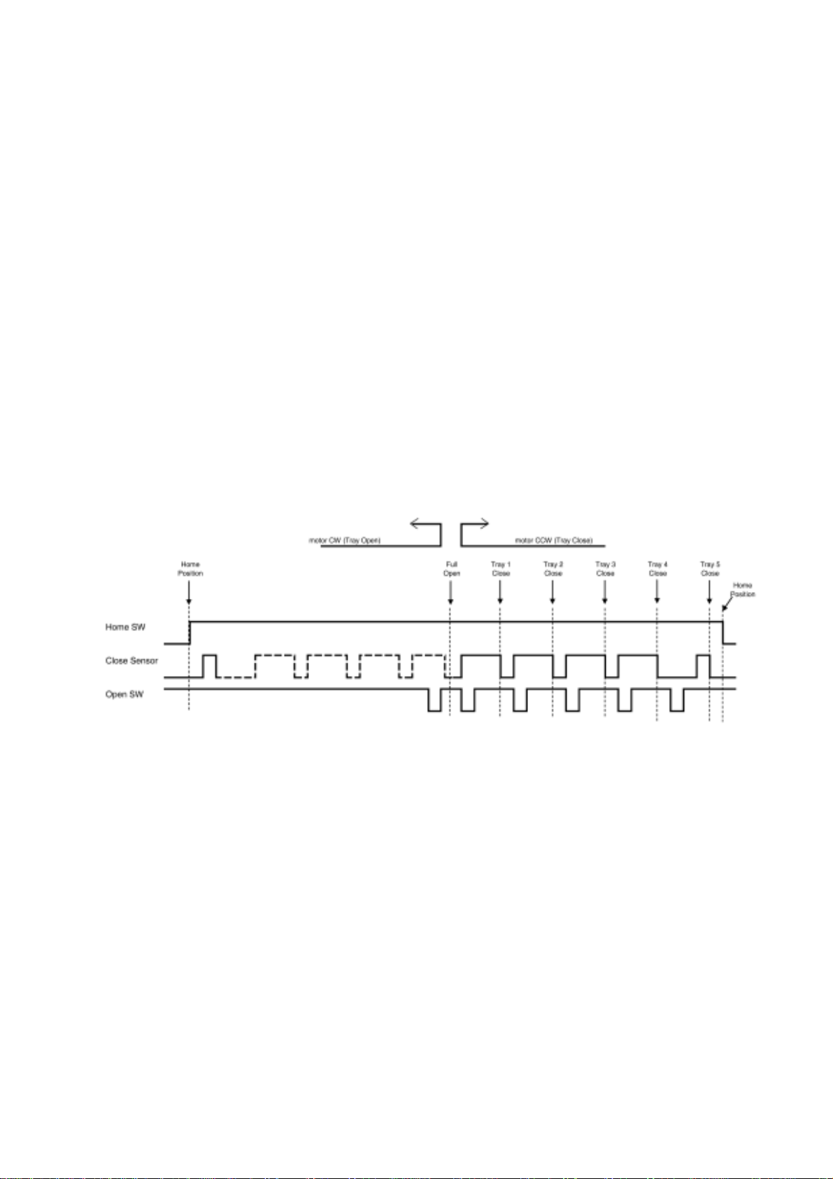
● Tray opening and closing is control by cam gear and CLOSE-SENSOR signal. OPEN-SW is
only use for full open operation in order to get more accurate tray stroke. Figure below show
the cam gear rotation direction for tray opening and closing, and cam important position.
● Below is the flow chart for tray open processing.
http://www.csweb.panasonic-la.com/viewing/ALL/CRS1/SVC/MD0509368C0/doc/MD0509368C0_03.xml (16 •• 26)13.08.2007 16:17:56
Page 35

http://www.csweb.panasonic-la.com/viewing/ALL/CRS1/SVC/MD0509368C0/doc/MD0509368C0_03.xml
● The flow charts below shown the types of tray close processing, for tray auto close processing
is use if user select a specify tray to be close automatically after trays full open.
● Tray change close processing use if use select a function and want to change disc one by one
from top tray to bottom tray.
● Close all processing is use when user wants to close all trays at once, or want to close tray
no.5 or close tray no.4 while tray no. 5 is at PLAY position.
http://www.csweb.panasonic-la.com/viewing/ALL/CRS1/SVC/MD0509368C0/doc/MD0509368C0_03.xml (17 •• 26)13.08.2007 16:17:56
Page 36

http://www.csweb.panasonic-la.com/viewing/ALL/CRS1/SVC/MD0509368C0/doc/MD0509368C0_03.xml
http://www.csweb.panasonic-la.com/viewing/ALL/CRS1/SVC/MD0509368C0/doc/MD0509368C0_03.xml (18 •• 26)13.08.2007 16:17:56
Page 37

http://www.csweb.panasonic-la.com/viewing/ALL/CRS1/SVC/MD0509368C0/doc/MD0509368C0_03.xml
● When there is a OPEN/CLOSE button pressed during tray open or tray close operation. Motor
will rotate revere direction. There are 2 type of cases, where 1 st is before full open condition
(open/close gear assembly still resting) and the 2nd is after trays full open condition. For the 1
st condition, motor will rotate the cam gear to move between HOME direction and tray open
direction. While for the 2 nd case, cam gear inside mechanism will move between specific
http://www.csweb.panasonic-la.com/viewing/ALL/CRS1/SVC/MD0509368C0/doc/MD0509368C0_03.xml (19 •• 26)13.08.2007 16:17:56
Page 38

http://www.csweb.panasonic-la.com/viewing/ALL/CRS1/SVC/MD0509368C0/doc/MD0509368C0_03.xml
positions by checking CLOSE-SENSOR signal change.
● The flow chart for both open reverse (when tray opening motor reverse) and close reverse
(when tray closing motor reverse) is as below. The operation use when user press OPEN/
CLOSE button during tray is opening or closing.
3.11 Drive tray between STOCK and PLAY position
● Play position is defined as the position whereas the tray is aligned to be played over the CD/
DVD unit. Only a single tray can be at this location & note that the traverse mechanism is at
its clamped position. Play position can be either disc playing (actively reading disc data) or its
not playing (no data reading).
* Shipment or Initialize positions always finish with a tray at this location.
● Loading operation is process to move tray from STOCK position to PLAY position.
● Unloading operation is process to move tray from PLAY position to STOCK position.
● If there is a certain operation key pressed at the middle of movement. The reversal operation
is necessary. The reversal operation should carry out after the tray arriving the STOCK
position or PLAY position.
● The flow chart and timing chart for load a disc from STOCK position to PLAY position is as
http://www.csweb.panasonic-la.com/viewing/ALL/CRS1/SVC/MD0509368C0/doc/MD0509368C0_03.xml (20 •• 26)13.08.2007 16:17:56
Page 39

http://www.csweb.panasonic-la.com/viewing/ALL/CRS1/SVC/MD0509368C0/doc/MD0509368C0_03.xml
below:
● The flow chart and timing chart for unload a disc from PLAY position to STOCK position is
as below:
3.12 Selection of Tray by Moving UD base Up/down
● Tray alignment & selection is achieved by UD (up/down) movement, whereas the Mechanism
vertically aligns itself to the selected tray to be driven to PLAY position or STOCK position.
The upper most tray is defined as tray 1 and bottom most tray is defined as tray 5. Counting is
achieved by resetting during initialization to the TOP-SW (tray 1) and counting the signal
change by UD-SENSOR.
● Below are the timing chart for UD base tray selection Up/down:
http://www.csweb.panasonic-la.com/viewing/ALL/CRS1/SVC/MD0509368C0/doc/MD0509368C0_03.xml (21 •• 26)13.08.2007 16:17:56
Page 40

http://www.csweb.panasonic-la.com/viewing/ALL/CRS1/SVC/MD0509368C0/doc/MD0509368C0_03.xml
● Tray 1 is the reset position for UD base up/down processing. The position should be unique; a
TOP-SW is use in this purpose.
● Below is the flow chart for UD selection processing.
http://www.csweb.panasonic-la.com/viewing/ALL/CRS1/SVC/MD0509368C0/doc/MD0509368C0_03.xml (22 •• 26)13.08.2007 16:17:56
Page 41

http://www.csweb.panasonic-la.com/viewing/ALL/CRS1/SVC/MD0509368C0/doc/MD0509368C0_03.xml
● For tray 1 selection, flow chart below will be used.
http://www.csweb.panasonic-la.com/viewing/ALL/CRS1/SVC/MD0509368C0/doc/MD0509368C0_03.xml (23 •• 26)13.08.2007 16:17:56
Page 42

http://www.csweb.panasonic-la.com/viewing/ALL/CRS1/SVC/MD0509368C0/doc/MD0509368C0_03.xml
3.13 Fail Safe
● Fail safe function is for purpose of recovery of tray movement if the mechanism is not able to
carry out tray open or close within a specified time.
Fail safe 1: Tray can not open: Fail safe - move all trays to home position
Fail safe 2: Tray can not close: Fail safe - move to next close sensor transition position
Note : For Fail safe 2 :
1. If done on tray 1 - will fully go to Open position because OC gears are fully engaged
2. If done on either one of the remaining trays (2, 3, 4 & 5) - will only release the gear
engagement and leave the tray at free condition, tray can only open manually by user.
After fail safe, any subsequent button pressed on main set, the mechanism must follow "GO HOME"
flowchart.
● Fail safe flow chart are shown as below:
http://www.csweb.panasonic-la.com/viewing/ALL/CRS1/SVC/MD0509368C0/doc/MD0509368C0_03.xml (24 •• 26)13.08.2007 16:17:56
Page 43

http://www.csweb.panasonic-la.com/viewing/ALL/CRS1/SVC/MD0509368C0/doc/MD0509368C0_03.xml
3.14 Manual Trigger Tray Close
● When user push open tray at full open position, user may able to activate tray to be all close.
This function will be disable if user happen to press "OPEN/CLOSE" button and fail safe
happen before.
http://www.csweb.panasonic-la.com/viewing/ALL/CRS1/SVC/MD0509368C0/doc/MD0509368C0_03.xml (25 •• 26)13.08.2007 16:17:56
Page 44

http://www.csweb.panasonic-la.com/viewing/ALL/CRS1/SVC/MD0509368C0/doc/MD0509368C0_03.xml
3.15 Changer Error Code
● The error code summary of CRS1 changer is as below:
Error
Code
Operation
IHMS Cam gear rotate to HOME position
ICLS
Cam gear rotate to Play Driving position to drive playing tray to STOCK
position
ISTK Move tray drive rack to STOCK position (drive tray to STOCK position)
IPLY Move tray drive rack to PLAY position (drive tray to PLAY position)
ITOP Move UD rack R to front direction (raise UD base to top position)
IUDS After TOP-SW detect, UD rack move to tray 1 position
HOME
After load tray to PLAY position, cam gear move to HOME
After unload to STOCK position, cam gear move to HOME
After all tray close, cam gear go to HOME position
LOAD Tray move from STOCK to PLAY position
UNLD Tray move from PLAY to STOCK position
PDRV Cam gear move from HOME to Play Driving position
UDU UD base move at up direction (from tray 5 to tray 2)
UDD UD base move at down direction (from tray 1 to tray 5)
UD1 UD base move to tray 1
F1NG Fail safe 1 NG (Fail safe 1 unsuccessful then try Fail Safe 2 also unsuccesful)
F2NG Fail safe 2 NG (Fail safe 2 unsuccessful then try Fail Safe 1 also unsuccesful)
http://www.csweb.panasonic-la.com/viewing/ALL/CRS1/SVC/MD0509368C0/doc/MD0509368C0_03.xml (26 •• 26)13.08.2007 16:17:56
Page 45

http://www.csweb.panasonic-la.com/viewing/ALL/CRS1/SVC/MD0509368C0/doc/MD0509368C0_04.xml
4 Self diagnosis and special mode setting
This unit is equipped with functions for checking and inspecting namely: Self-Diagnostic and Test
Mode.
4.1 Special Mode Table
Item
FL Display
Key Operation
Mode Name Description Front Key
Self -
Diagnostic
Mode
To enter into
self diagnostic
checking for
main unit.
1. Select [
] for
TAPE mode (Ensure no
tape is inserted).
2. Press and hold [
]button for 3
seconds follow by [
].
To exit, press
button on
main unit or remote control.
CD Test
Mode
To enter into
checking the
reliability of
changer unit.
1. Select [
] for CD
mode.
2. Press and hold [
] button for 3
seconds follow by [
].
To exit, press
button on
main unit or remote control.
CD Auto
Adjustment
To check the
CD auto
adjustment
result for
FLOCK,
TLOCK and
CLVS.
In CD Test Mode:
1. Press [0] button on the
remote control.
To exit, press
button on
main unit or remote control.
CD Changer
Reliability
Test (CRS1)
To determine
the reliability
of CD
Changer Unit.
(For more
information,
refer to
section 4.1.1)
In Self-Diagnostic Mode:
1. Select [
] for CD
mode.
2. Press [
]
button.
To exit, press
button on
main unit or remote control.
(The tray will return to PLAY
position and then power off)
http://www.csweb.panasonic-la.com/viewing/ALL/CRS1/SVC/MD0509368C0/doc/MD0509368C0_04.xml (1 •• 7)13.08.2007 16:18:27
Page 46

http://www.csweb.panasonic-la.com/viewing/ALL/CRS1/SVC/MD0509368C0/doc/MD0509368C0_04.xml
Doctor Mode
To enter into
Doctor Mode
for checking
of various
items and
displaying
EEPROM and
firmware
version.
1.
2.
1. All segments will light up for 1
second.
2. The Check Sum of EEPROM and
firmware version will be display.
* ROM correction
** Firmware version No:
In any mode:
1. Press [
] button
on main unit follow by
[4] and [7] on remote
control.
To exit, press [ENTER] button on
remote control or
button
on main unit or remote control.
Cold Start
To activate
cold start upon
next AC
power up.
In doctor mode:
1. Press [4] button on
remote control.
To exit, press [ENTER] button on
remote control or
button
on main unit or remote control.
Changer
Reliability
Test
To check the
function
operation of
changer unit.
(For more
information,
refer to 4.1.1)
In doctor mode:
1. Press [DISC] on remote
control.
To exit, press [ENTER] button on
remote control or
button
on main unit or remote control.
FL Display
Test
To check the
FL segments
display (All
segments will
light up and
LED will
blink at 0.5
second
interval)
In doctor mode:
1. Press [PROGRAM]
button on remote
control.
Tape Eject
Test
To check on
the tape eject
function (For
deck 1/2)
In doctor mode:
1. Press [PROGRAM]
button on remote
control.
4.1.1 CD changer unit ageing test mode
Below is the process flow chart of ageing for the CD changer unit.
http://www.csweb.panasonic-la.com/viewing/ALL/CRS1/SVC/MD0509368C0/doc/MD0509368C0_04.xml (2 •• 7)13.08.2007 16:18:27
Page 47

http://www.csweb.panasonic-la.com/viewing/ALL/CRS1/SVC/MD0509368C0/doc/MD0509368C0_04.xml
http://www.csweb.panasonic-la.com/viewing/ALL/CRS1/SVC/MD0509368C0/doc/MD0509368C0_04.xml (3 •• 7)13.08.2007 16:18:27
Page 48

http://www.csweb.panasonic-la.com/viewing/ALL/CRS1/SVC/MD0509368C0/doc/MD0509368C0_04.xml
4.2 Error code Table
Self-Diagnosis Function (refer Section 4.1) provides information on any problems occuring for the
unit and its respective components by displaying the error codes. These error code such as U**, H**
and F** are stored in memory and held unless it is cleared.
The error code is automatically display after entering into self-diagnostic mode.
Error Code
Diagnosis
Contents
Description of error Automatic FL Display Remarks
IHMS
Cam gear
abnormality
Cam gear does not rotate to “HOME”
position.
For CD changer
unit (CRS1).
Press [SINGLE
CHANGE] on
main unit for
next error.
http://www.csweb.panasonic-la.com/viewing/ALL/CRS1/SVC/MD0509368C0/doc/MD0509368C0_04.xml (4 •• 7)13.08.2007 16:18:27
Page 49

http://www.csweb.panasonic-la.com/viewing/ALL/CRS1/SVC/MD0509368C0/doc/MD0509368C0_04.xml
ICSL
Cam gear/gear
units abnormal
Cam gear does not rotate to “PLAY” driving
position and hence does not drive playing
tray to “STOCK” position.
For CD changer
unit (CRS1).
Press [SINGLE
CHANGE] on
main unit for
next error.
ISTK
Drive rack/gear
assembly
abnormal
The tray drive rack does not move to
“STOCK” position. (Tray does not move to
“STOCK” position)
For CD changer
unit (CRS1).
Press [SINGLE
CHANGE] on
main unit for
next error.
IPLY
Drive rack/gear
assembly
abnormal
The tray drive rack does not move to
“PLAY” position. (Tray does not move to
“PLAY” position)
For CD changer
unit (CRS1).
Press [SINGLE
CHANGE] on
main unit for
next error.
ITOP UD assembly
UD Rack does not move to front direction.
This lead to UD base not raise to top
position.
For CD changer
unit (CRS1).
Press [SINGLE
CHANGE] on
main unit for
next error.
IUDS UD assembly
After TOP SW is detected, UD rack does not
move into tray 1 position.
For CD changer
unit (CRS1).
Press [SINGLE
CHANGE] on
main unit for
next error.
HOME
Cam gear/gear
assembly
abnormal
Cam gear does not move to “HOME”
position under following conditions
1. After tray is load to “PLAY”
position.
2. After tray is unload to
“STOCK” position.
For CD changer
unit (CRS1).
Press [SINGLE
CHANGE] on
main unit for
next error.
LOAD
Tray drive
assembly
abnormal
Tray unit does not move from “STOCK” to
“PLAY” position
For CD changer
unit (CRS1).
Press [SINGLE
CHANGE] on
main unit for
next error.
http://www.csweb.panasonic-la.com/viewing/ALL/CRS1/SVC/MD0509368C0/doc/MD0509368C0_04.xml (5 •• 7)13.08.2007 16:18:27
Page 50

http://www.csweb.panasonic-la.com/viewing/ALL/CRS1/SVC/MD0509368C0/doc/MD0509368C0_04.xml
PDRV
Cam gear/gear
assembly
abnormal
Cam gear does not move from “HOME” to
“PLAY” drive position.
For CD changer
unit (CRS1).
Press [SINGLE
CHANGE] on
main unit for
next error.
UDU
UD base
asssembly
abnormal
UD Base assembly does not move upwards
from tray 5 to tray 2
For CD changer
unit (CRS1).
Press [SINGLE
CHANGE] on
main unit for
next error.
UDD
UD base
asssembly
abnormal
UD Base assembly does not move
downwards from tray 1 to tray 5
.
For CD changer
unit (CRS1).
Press [SINGLE
CHANGE] on
main unit for
next error.
UD1
UD base
asssembly
abnormal
UD Base assembly does not move to tray 1
.
For CD changer
unit (CRS1).
Press [SINGLE
CHANGE] on
main unit for
next error.
F1NG
Fail - safe mode.
(For open/close
tray unit(s))
When the tray open operation is performed,
it fails to open. It will automatically close all
trays after the time-out by the
microprocessor. During this time when it
fails, the error code will appear.
For CD changer
unit (CRS1).
Press [SINGLE
CHANGE] on
main unit for
next error.
F2NG
Fail - safe mode.
(For open/close
tray unit(s))
When the tray close operation is performed,
it fails to close. It will automatically open all
trays after the time-out by the
microprocessor. During this time when it
fails, the error code will appear.
For CD changer
unit (CRS1).
Press [SINGLE
CHANGE] on
main unit for
next error.
SRVC_TRV
To unlock the
traverse unit for
service
1. All trays set to “STOCK”
position
2. Mechanism set to tray 5
3. Cam gear set to “HOME”
position
For CD changer
unit (CRS1).
Press [SINGLE
CHANGE] on
main unit.
http://www.csweb.panasonic-la.com/viewing/ALL/CRS1/SVC/MD0509368C0/doc/MD0509368C0_04.xml (6 •• 7)13.08.2007 16:18:27
Page 51

http://www.csweb.panasonic-la.com/viewing/ALL/CRS1/SVC/MD0509368C0/doc/MD0509368C0_04.xml
RSET
Cam gear jam/
close sensor
faulty
During tray re-open, the cam gear will rotate
in the opposite direction to reset the cam
gearposition. When it fails, the error code
will appear.
For CD changer
unit (CRS1).
Press [SINGLE
CHANGE] on
main unit for
next error.
CRS1 Error Code display
1. The errors that occured in CRS1 Mechanism can be recalled and displayed, in the order of
the occurence under self-diagnostic (Refer to Section 4.1 for procedures to enter this
mode.
❍ Only the first 5 errors will be memorized (in backup memory). The
subsequence error shall be ignored and not memorize.
For system with EEPROM as memory backup,memory space in EEPROM is
neccesary.
2. To display all error code memorized
In CRS1 Self-Diagnostic mode, press [SINGLE CHANGE] to display subsequence error
code.
It shall repeat after reaching error no. 5.
e.g.:
[1 _ _ _ _ I H M S] → [SINGLE CHANGE]
[2 _ _ _ _ I T O P] → [SINGLE CHANGE]
[3 _ _ _ _ H O M E] → [SINGLE CHANGE]
[4 _ _ _ _ L O A D] → [SINGLE CHANGE]
[5 _ _ _ _ _ U D D] → [SINGLE CHANGE]
3. To clear the error code memory
In CRS1 Self-Diagnostic mode, long press [SINGLE CHANGE] key (2s or more)
http://www.csweb.panasonic-la.com/viewing/ALL/CRS1/SVC/MD0509368C0/doc/MD0509368C0_04.xml (7 •• 7)13.08.2007 16:18:27
Page 52

http://www.csweb.panasonic-la.com/viewing/ALL/CRS1/SVC/MD0509368C0/doc/MD0509368C0_05.xml
5 Troubleshooting Explorer 5.1 Preparation of service jig
● This unit has a gear which is used for checking items (open/close of disc tray, up/down
operation of traverse unit by manually) when servicing. (For gear information, that is
described on the items for disassembly procedures.)
● For preparation of gear (for servicing), perform the procedures as follows.
● In case of re-servicing the same set, the “gear for servicing” may be took off because it
had been used. So, the “gear for servicing” must be stored.
5.2 Checking of Changer Unit
Below is the procedures for checking the function of the changer unit.
Step 1: Enter into doctor mode.
Step 2: Press [DISC] on remote control unit.
Step 3: Error code will appear if there is any function problems. (Pls refer to section 4.2 on more
information of error code).
5.3 Setting the trays in “STOCK” position
● Below is procedures for setting the main unit into service mode:-
1. Enter into self-diagnostic (Refer to section 4.1)
2. Press [SINGLE CHANGE] on main unit.
● If fail to set the main unit into service mode, do it manually by the below procedures
http://www.csweb.panasonic-la.com/viewing/ALL/CRS1/SVC/MD0509368C0/doc/MD0509368C0_05.xml (1 •• 15)13.08.2007 16:19:00
Page 53

http://www.csweb.panasonic-la.com/viewing/ALL/CRS1/SVC/MD0509368C0/doc/MD0509368C0_05.xml
5.3.1 No CD in the tray
http://www.csweb.panasonic-la.com/viewing/ALL/CRS1/SVC/MD0509368C0/doc/MD0509368C0_05.xml (2 •• 15)13.08.2007 16:19:00
Page 54

http://www.csweb.panasonic-la.com/viewing/ALL/CRS1/SVC/MD0509368C0/doc/MD0509368C0_05.xml
http://www.csweb.panasonic-la.com/viewing/ALL/CRS1/SVC/MD0509368C0/doc/MD0509368C0_05.xml (3 •• 15)13.08.2007 16:19:00
Page 55

http://www.csweb.panasonic-la.com/viewing/ALL/CRS1/SVC/MD0509368C0/doc/MD0509368C0_05.xml
http://www.csweb.panasonic-la.com/viewing/ALL/CRS1/SVC/MD0509368C0/doc/MD0509368C0_05.xml (4 •• 15)13.08.2007 16:19:00
Page 56

http://www.csweb.panasonic-la.com/viewing/ALL/CRS1/SVC/MD0509368C0/doc/MD0509368C0_05.xml
5.3.2 When CD in the tray
http://www.csweb.panasonic-la.com/viewing/ALL/CRS1/SVC/MD0509368C0/doc/MD0509368C0_05.xml (5 •• 15)13.08.2007 16:19:00
Page 57

http://www.csweb.panasonic-la.com/viewing/ALL/CRS1/SVC/MD0509368C0/doc/MD0509368C0_05.xml
http://www.csweb.panasonic-la.com/viewing/ALL/CRS1/SVC/MD0509368C0/doc/MD0509368C0_05.xml (6 •• 15)13.08.2007 16:19:00
Page 58

http://www.csweb.panasonic-la.com/viewing/ALL/CRS1/SVC/MD0509368C0/doc/MD0509368C0_05.xml
http://www.csweb.panasonic-la.com/viewing/ALL/CRS1/SVC/MD0509368C0/doc/MD0509368C0_05.xml (7 •• 15)13.08.2007 16:19:00
Page 59

http://www.csweb.panasonic-la.com/viewing/ALL/CRS1/SVC/MD0509368C0/doc/MD0509368C0_05.xml
http://www.csweb.panasonic-la.com/viewing/ALL/CRS1/SVC/MD0509368C0/doc/MD0509368C0_05.xml (8 •• 15)13.08.2007 16:19:00
Page 60

http://www.csweb.panasonic-la.com/viewing/ALL/CRS1/SVC/MD0509368C0/doc/MD0509368C0_05.xml
http://www.csweb.panasonic-la.com/viewing/ALL/CRS1/SVC/MD0509368C0/doc/MD0509368C0_05.xml (9 •• 15)13.08.2007 16:19:00
Page 61

http://www.csweb.panasonic-la.com/viewing/ALL/CRS1/SVC/MD0509368C0/doc/MD0509368C0_05.xml
http://www.csweb.panasonic-la.com/viewing/ALL/CRS1/SVC/MD0509368C0/doc/MD0509368C0_05.xml (10 •• 15)13.08.2007 16:19:00
Page 62

http://www.csweb.panasonic-la.com/viewing/ALL/CRS1/SVC/MD0509368C0/doc/MD0509368C0_05.xml
http://www.csweb.panasonic-la.com/viewing/ALL/CRS1/SVC/MD0509368C0/doc/MD0509368C0_05.xml (11 •• 15)13.08.2007 16:19:00
Page 63

http://www.csweb.panasonic-la.com/viewing/ALL/CRS1/SVC/MD0509368C0/doc/MD0509368C0_05.xml
http://www.csweb.panasonic-la.com/viewing/ALL/CRS1/SVC/MD0509368C0/doc/MD0509368C0_05.xml (12 •• 15)13.08.2007 16:19:00
Page 64

http://www.csweb.panasonic-la.com/viewing/ALL/CRS1/SVC/MD0509368C0/doc/MD0509368C0_05.xml
http://www.csweb.panasonic-la.com/viewing/ALL/CRS1/SVC/MD0509368C0/doc/MD0509368C0_05.xml (13 •• 15)13.08.2007 16:19:00
Page 65

http://www.csweb.panasonic-la.com/viewing/ALL/CRS1/SVC/MD0509368C0/doc/MD0509368C0_05.xml
http://www.csweb.panasonic-la.com/viewing/ALL/CRS1/SVC/MD0509368C0/doc/MD0509368C0_05.xml (14 •• 15)13.08.2007 16:19:00
Page 66

http://www.csweb.panasonic-la.com/viewing/ALL/CRS1/SVC/MD0509368C0/doc/MD0509368C0_05.xml
http://www.csweb.panasonic-la.com/viewing/ALL/CRS1/SVC/MD0509368C0/doc/MD0509368C0_05.xml (15 •• 15)13.08.2007 16:19:00
Page 67

http://www.csweb.panasonic-la.com/viewing/ALL/CRS1/SVC/MD0509368C0/doc/MD0509368C0_07.xml
7 Assembling and Disassembling Procedure. 7.1 Disassembling Procedures Caution:
Do ensure that the main unit is set to service mode before repair.
For information on setting to service mode for changer unit, pls refer to section 5.3.
Note:
Change unit (CRS1) reliability test must be carry out in complete unit or using the Service P.C.B
(Refer section 8).
7.1.1 Disassembly of UD Base Assembly
http://www.csweb.panasonic-la.com/viewing/ALL/CRS1/SVC/MD0509368C0/doc/MD0509368C0_07.xml (1 •• 64)13.08.2007 16:22:31
Page 68

http://www.csweb.panasonic-la.com/viewing/ALL/CRS1/SVC/MD0509368C0/doc/MD0509368C0_07.xml
http://www.csweb.panasonic-la.com/viewing/ALL/CRS1/SVC/MD0509368C0/doc/MD0509368C0_07.xml (2 •• 64)13.08.2007 16:22:31
Page 69

http://www.csweb.panasonic-la.com/viewing/ALL/CRS1/SVC/MD0509368C0/doc/MD0509368C0_07.xml
http://www.csweb.panasonic-la.com/viewing/ALL/CRS1/SVC/MD0509368C0/doc/MD0509368C0_07.xml (3 •• 64)13.08.2007 16:22:31
Page 70

http://www.csweb.panasonic-la.com/viewing/ALL/CRS1/SVC/MD0509368C0/doc/MD0509368C0_07.xml
http://www.csweb.panasonic-la.com/viewing/ALL/CRS1/SVC/MD0509368C0/doc/MD0509368C0_07.xml (4 •• 64)13.08.2007 16:22:31
Page 71

http://www.csweb.panasonic-la.com/viewing/ALL/CRS1/SVC/MD0509368C0/doc/MD0509368C0_07.xml
http://www.csweb.panasonic-la.com/viewing/ALL/CRS1/SVC/MD0509368C0/doc/MD0509368C0_07.xml (5 •• 64)13.08.2007 16:22:31
Page 72

http://www.csweb.panasonic-la.com/viewing/ALL/CRS1/SVC/MD0509368C0/doc/MD0509368C0_07.xml
7.1.2 Disassembly of Disc Trays
● Follow the (Step 1) to (Step 13) of item 7.1.1. (Disassembly of UD Base Assembly)
● Disassembly of UD connection lever
http://www.csweb.panasonic-la.com/viewing/ALL/CRS1/SVC/MD0509368C0/doc/MD0509368C0_07.xml (6 •• 64)13.08.2007 16:22:31
Page 73

http://www.csweb.panasonic-la.com/viewing/ALL/CRS1/SVC/MD0509368C0/doc/MD0509368C0_07.xml
http://www.csweb.panasonic-la.com/viewing/ALL/CRS1/SVC/MD0509368C0/doc/MD0509368C0_07.xml (7 •• 64)13.08.2007 16:22:31
Page 74

http://www.csweb.panasonic-la.com/viewing/ALL/CRS1/SVC/MD0509368C0/doc/MD0509368C0_07.xml
http://www.csweb.panasonic-la.com/viewing/ALL/CRS1/SVC/MD0509368C0/doc/MD0509368C0_07.xml (8 •• 64)13.08.2007 16:22:31
Page 75

http://www.csweb.panasonic-la.com/viewing/ALL/CRS1/SVC/MD0509368C0/doc/MD0509368C0_07.xml
http://www.csweb.panasonic-la.com/viewing/ALL/CRS1/SVC/MD0509368C0/doc/MD0509368C0_07.xml (9 •• 64)13.08.2007 16:22:31
Page 76

http://www.csweb.panasonic-la.com/viewing/ALL/CRS1/SVC/MD0509368C0/doc/MD0509368C0_07.xml
7.1.3 Disassembly of CD Loading Unit
http://www.csweb.panasonic-la.com/viewing/ALL/CRS1/SVC/MD0509368C0/doc/MD0509368C0_07.xml (10 •• 64)13.08.2007 16:22:31
Page 77

http://www.csweb.panasonic-la.com/viewing/ALL/CRS1/SVC/MD0509368C0/doc/MD0509368C0_07.xml
● Follow the (Step 1) to (Step 13) of item 7.1.1. (Disassembly of UD Base Assembly)
● Follow the (Step 1) to (Step 6) of item 7.1.2. (Disassembly of Disc Trays)
● Disassembly of play lever B
● Disassembly of tray drive rack
http://www.csweb.panasonic-la.com/viewing/ALL/CRS1/SVC/MD0509368C0/doc/MD0509368C0_07.xml (11 •• 64)13.08.2007 16:22:31
Page 78

http://www.csweb.panasonic-la.com/viewing/ALL/CRS1/SVC/MD0509368C0/doc/MD0509368C0_07.xml
● Disassembly of UD rack L
http://www.csweb.panasonic-la.com/viewing/ALL/CRS1/SVC/MD0509368C0/doc/MD0509368C0_07.xml (12 •• 64)13.08.2007 16:22:31
Page 79

http://www.csweb.panasonic-la.com/viewing/ALL/CRS1/SVC/MD0509368C0/doc/MD0509368C0_07.xml
http://www.csweb.panasonic-la.com/viewing/ALL/CRS1/SVC/MD0509368C0/doc/MD0509368C0_07.xml (13 •• 64)13.08.2007 16:22:31
Page 80

http://www.csweb.panasonic-la.com/viewing/ALL/CRS1/SVC/MD0509368C0/doc/MD0509368C0_07.xml
● Disassembly of UD rack R
http://www.csweb.panasonic-la.com/viewing/ALL/CRS1/SVC/MD0509368C0/doc/MD0509368C0_07.xml (14 •• 64)13.08.2007 16:22:31
Page 81

http://www.csweb.panasonic-la.com/viewing/ALL/CRS1/SVC/MD0509368C0/doc/MD0509368C0_07.xml
http://www.csweb.panasonic-la.com/viewing/ALL/CRS1/SVC/MD0509368C0/doc/MD0509368C0_07.xml (15 •• 64)13.08.2007 16:22:32
Page 82

http://www.csweb.panasonic-la.com/viewing/ALL/CRS1/SVC/MD0509368C0/doc/MD0509368C0_07.xml
● Disassembly of trigger gear
● Disassembly of pitch plate
http://www.csweb.panasonic-la.com/viewing/ALL/CRS1/SVC/MD0509368C0/doc/MD0509368C0_07.xml (16 •• 64)13.08.2007 16:22:32
Page 83

http://www.csweb.panasonic-la.com/viewing/ALL/CRS1/SVC/MD0509368C0/doc/MD0509368C0_07.xml
● Disassembly of lock lever 2
● Disassembly of change spring
http://www.csweb.panasonic-la.com/viewing/ALL/CRS1/SVC/MD0509368C0/doc/MD0509368C0_07.xml (17 •• 64)13.08.2007 16:22:32
Page 84

http://www.csweb.panasonic-la.com/viewing/ALL/CRS1/SVC/MD0509368C0/doc/MD0509368C0_07.xml
● Disassembly of pulley gear and belt
● Disassembly of gears
http://www.csweb.panasonic-la.com/viewing/ALL/CRS1/SVC/MD0509368C0/doc/MD0509368C0_07.xml (18 •• 64)13.08.2007 16:22:32
Page 85

http://www.csweb.panasonic-la.com/viewing/ALL/CRS1/SVC/MD0509368C0/doc/MD0509368C0_07.xml
http://www.csweb.panasonic-la.com/viewing/ALL/CRS1/SVC/MD0509368C0/doc/MD0509368C0_07.xml (19 •• 64)13.08.2007 16:22:32
Page 86

http://www.csweb.panasonic-la.com/viewing/ALL/CRS1/SVC/MD0509368C0/doc/MD0509368C0_07.xml
● Disassembly of cam gear
● Disassembly of function gear and main drive gear
http://www.csweb.panasonic-la.com/viewing/ALL/CRS1/SVC/MD0509368C0/doc/MD0509368C0_07.xml (20 •• 64)13.08.2007 16:22:32
Page 87

http://www.csweb.panasonic-la.com/viewing/ALL/CRS1/SVC/MD0509368C0/doc/MD0509368C0_07.xml
● Disassembly of play gear 1
http://www.csweb.panasonic-la.com/viewing/ALL/CRS1/SVC/MD0509368C0/doc/MD0509368C0_07.xml (21 •• 64)13.08.2007 16:22:32
Page 88

http://www.csweb.panasonic-la.com/viewing/ALL/CRS1/SVC/MD0509368C0/doc/MD0509368C0_07.xml
● Disassembly of function lever
7.1.4 Disassembly of CD Loading P.C.B.
http://www.csweb.panasonic-la.com/viewing/ALL/CRS1/SVC/MD0509368C0/doc/MD0509368C0_07.xml (22 •• 64)13.08.2007 16:22:32
Page 89

http://www.csweb.panasonic-la.com/viewing/ALL/CRS1/SVC/MD0509368C0/doc/MD0509368C0_07.xml
http://www.csweb.panasonic-la.com/viewing/ALL/CRS1/SVC/MD0509368C0/doc/MD0509368C0_07.xml (23 •• 64)13.08.2007 16:22:32
Page 90

http://www.csweb.panasonic-la.com/viewing/ALL/CRS1/SVC/MD0509368C0/doc/MD0509368C0_07.xml
● Disassembly of plunger assembly
7.1.5 Disassembly of Plunger Lever
● Follow the (Step 1) to (Step 13) of item 7.1.1. (Disassembly of UD Base Assembly)
● Follow the (Step 1) to (Step 6) of item 7.1.2. (Disassembly of Disc Trays)
● Follow the (Step 1) to (Step 18) of item 7.1.3. (Disassembly of CD Loading Unit)
● Follow the (Step 1) to (Step 5) of item 7.1.4. (Disassembly of CD Loading P.C.B.)
http://www.csweb.panasonic-la.com/viewing/ALL/CRS1/SVC/MD0509368C0/doc/MD0509368C0_07.xml (24 •• 64)13.08.2007 16:22:32
Page 91

http://www.csweb.panasonic-la.com/viewing/ALL/CRS1/SVC/MD0509368C0/doc/MD0509368C0_07.xml
http://www.csweb.panasonic-la.com/viewing/ALL/CRS1/SVC/MD0509368C0/doc/MD0509368C0_07.xml (25 •• 64)13.08.2007 16:22:32
Page 92

http://www.csweb.panasonic-la.com/viewing/ALL/CRS1/SVC/MD0509368C0/doc/MD0509368C0_07.xml
7.1.6 Disassembly of Motor Unit
● Follow the (Step 1) to (Step 13) of item 7.1.1. (Disassembly of UD Base Assembly)
● Follow the (Step 1) to (Step 6) of item 7.1.2. (Disassembly of Disc Trays)
● Follow the (Step 1) to (Step 16) of item 7.1.3. (Disassembly of CD Loading Unit)
● Follow the (Step 1) to (Step 4) of item 7.1.4. (Disassembly of CD Loading P.C.B.)
http://www.csweb.panasonic-la.com/viewing/ALL/CRS1/SVC/MD0509368C0/doc/MD0509368C0_07.xml (26 •• 64)13.08.2007 16:22:32
Page 93

http://www.csweb.panasonic-la.com/viewing/ALL/CRS1/SVC/MD0509368C0/doc/MD0509368C0_07.xml
7.1.7 Disassembly of Traverse Unit Important notes:
Ensure all the trays are in the “STOCK” position before proceeding to the disassemble of traverse
unit. For procedures to set the trays in “STOCK” position, please refer to (5. Troubleshooting
http://www.csweb.panasonic-la.com/viewing/ALL/CRS1/SVC/MD0509368C0/doc/MD0509368C0_07.xml (27 •• 64)13.08.2007 16:22:32
Page 94

http://www.csweb.panasonic-la.com/viewing/ALL/CRS1/SVC/MD0509368C0/doc/MD0509368C0_07.xml
Explorer)
http://www.csweb.panasonic-la.com/viewing/ALL/CRS1/SVC/MD0509368C0/doc/MD0509368C0_07.xml (28 •• 64)13.08.2007 16:22:32
Page 95

http://www.csweb.panasonic-la.com/viewing/ALL/CRS1/SVC/MD0509368C0/doc/MD0509368C0_07.xml
7.1.8 Disassembly of Limit Spring
● Follow the (Step 1) to (Step 9) of item 7.1.1. (Disassembly of UD Base Assembly)
7.1.9 Disassembly of Play Lever Spring
● Follow the (Step 1) to (Step 13) of item 7.1.1. (Disassembly of UD Base Assembly)
● Follow the (Step 1) to (Step 6) of item 7.1.2. (Disassembly of Disc Trays)
● Follow the (Step 1) to (Step 26) of item 7.1.3. (Disassembly of CD Loading Unit)
7.1.10 Disassembly of Pitch Plate Assembly
● Follow the (Step 1) to (Step 13) of item 7.1.1. (Disassembly of UD Base Assembly)
● Follow the (Step 1) to (Step 6) of item 7.1.2. (Disassembly of Disc Trays)
http://www.csweb.panasonic-la.com/viewing/ALL/CRS1/SVC/MD0509368C0/doc/MD0509368C0_07.xml (29 •• 64)13.08.2007 16:22:32
Page 96

http://www.csweb.panasonic-la.com/viewing/ALL/CRS1/SVC/MD0509368C0/doc/MD0509368C0_07.xml
● Follow the (Step 1) to (Step 3) of item 7.1.3. (Disassembly of CD Loading Unit)
http://www.csweb.panasonic-la.com/viewing/ALL/CRS1/SVC/MD0509368C0/doc/MD0509368C0_07.xml (30 •• 64)13.08.2007 16:22:32
Page 97

http://www.csweb.panasonic-la.com/viewing/ALL/CRS1/SVC/MD0509368C0/doc/MD0509368C0_07.xml
7.2 Assembling Procedure 7.2.1 Assembly of CD Loading
Unit
● Assembly of Plunger Lever
http://www.csweb.panasonic-la.com/viewing/ALL/CRS1/SVC/MD0509368C0/doc/MD0509368C0_07.xml (31 •• 64)13.08.2007 16:22:32
Page 98

http://www.csweb.panasonic-la.com/viewing/ALL/CRS1/SVC/MD0509368C0/doc/MD0509368C0_07.xml
● Assembly of Motor Unit
http://www.csweb.panasonic-la.com/viewing/ALL/CRS1/SVC/MD0509368C0/doc/MD0509368C0_07.xml (32 •• 64)13.08.2007 16:22:32
Page 99

http://www.csweb.panasonic-la.com/viewing/ALL/CRS1/SVC/MD0509368C0/doc/MD0509368C0_07.xml
● Assembly of Plunger Assembly
● Assembly of CD Loading P.C.B.
http://www.csweb.panasonic-la.com/viewing/ALL/CRS1/SVC/MD0509368C0/doc/MD0509368C0_07.xml (33 •• 64)13.08.2007 16:22:32
Page 100

http://www.csweb.panasonic-la.com/viewing/ALL/CRS1/SVC/MD0509368C0/doc/MD0509368C0_07.xml
http://www.csweb.panasonic-la.com/viewing/ALL/CRS1/SVC/MD0509368C0/doc/MD0509368C0_07.xml (34 •• 64)13.08.2007 16:22:32
 Loading...