

Page 1
Operating
Instructions
VmEOCiPHER'n
INTEGRATED SATELLITE RECEIVER/
POSmONER/DESCRAMBLER
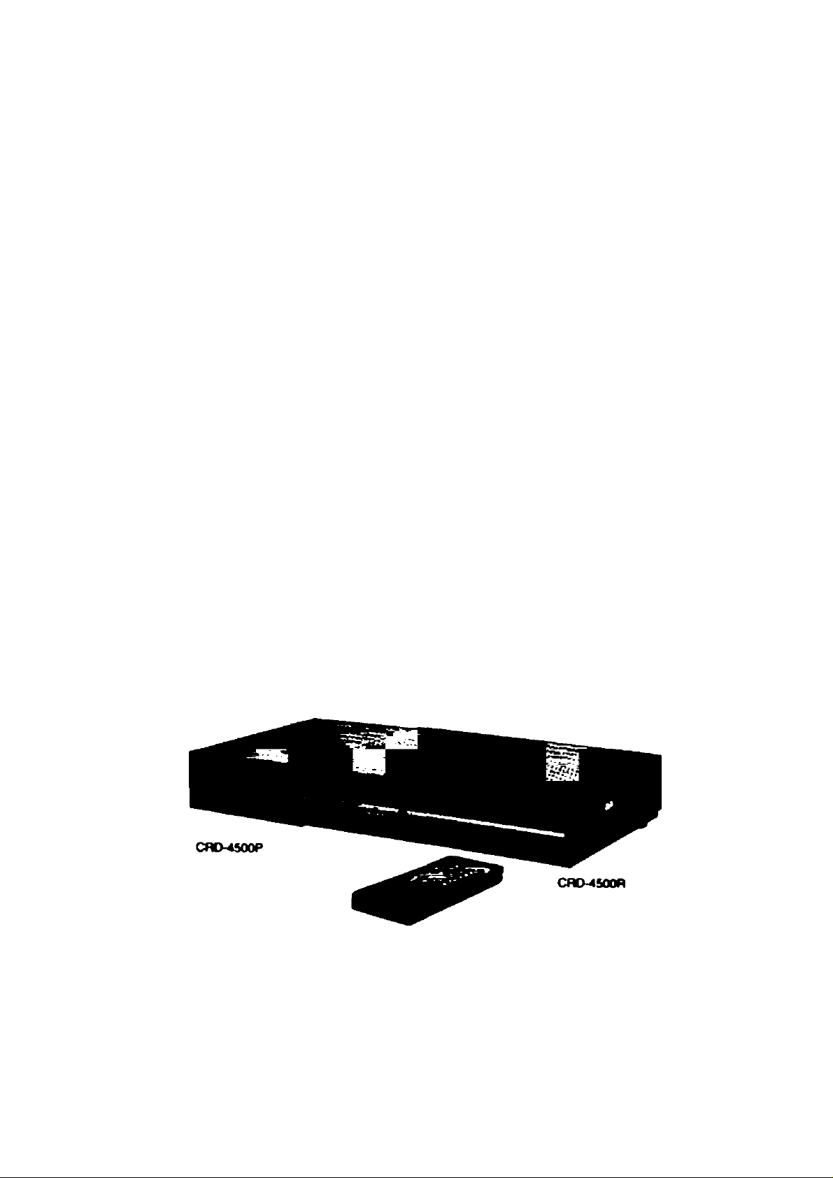
Model No. CRD-4500
Satellite Receiver
Power Supply
Remote Controller
CRD-4500R
CRD-4500P
RMC-4500
RMC-iSOO
CRD-4500
Panasonic.
Read these instnictions completely, before operating this set.
TOB510066
Page 2
INTRODUCTION
DEAR PANASONIC CUSTOMER
Congratulation on your purchase of a new Panasonic CRD-4500 Integrated Satellite Receiver/Positioner/Descrambler, It
represents the state-of-the-art in television viewing. CRD-4500 is an integrated satellite receiver/positioner/descrambler com
posed of a receiver unit [CRD-4500R]; a power supply [CRD-4500P]; a remote controller [RMC-4500]: and a built-in descram
bler [VideoCipher n ].
* See page 23.
IMPORTANT SAFETY NOTICE
WARNING:
To prevent damage which may result in fire or shock hazard, do not expose this appiiance to rain or moisture.
WARNING:
Remove plug from wall outlet when the unit is not in use for a prolonged period of time.
The lightning flash with arrowhead symbol,
CAUTION
RISK OF ELECTRIC SHOCK
DO NOT OPEN
CAUTION: TO REDUCE THE RISK OF ELECTRIC SHOCK.
DO NOT REMOVE COVER (OR BACK)
NO USER-SERVICEABLE PARTS INSIDE
REFER SERVICING TO QUALIFIED SERVICE PERSONNEL
“This equipment has been tested and found to comply with the limits for a Class B computing device in accordance with the
specifications set forth in Subpart J of Part 15 of the FCC Rules. If this equipment does cause interference to radio or
television reception which can be determined by turning the equipment on and off, use the equipment in another location
and/or utilize an electrical outlet different from that used by the receiver."
within an equilateral triangle, is intended to
alert the user to the presence of uninsu
lated “dangerous voltage” within the pro
duct’s enclosure that may be of sufficient
magnitude to constitute a risk of electric
shock to persons.
The exclamation point within an equilateral
triangle is intended to alert the user to the
presence of important operating and main
tenance (servicing) instructions in the liter
ature accompanying the appliance.
To comply with FCC rules regarding emission limits, shielded cables must be used when connecting this device
to other equipment.
CAUTION:
Do not remove the grounding pin on the power plug.
This equipment is equipped with a three grounding-type power plug. This plug will only fit a grounding-type power outlet.
This is a safety feature. If you are unable to insert the plug into the outlet, contact an electrician.
Do not defeat the purpose of the grounding plug.
- 1 -
Do not remove
Page 3

Note to CATV system installer:
This reminder is provided to call the CATV system installer’s attention to Article 820-22 of the NEC
that provides guidelines for proper grounding and, in particular, specifies that the cable ground shall
be connected to the grounding system of the building, as close to the point of cable entry as practical.
CONTENTS_____________________________
INTRODUCTION ................................................................................................................................................................................. 1
IMPORTANT SAFETY NOTICE .......................................................................................................................................................... 1
CONTENTS...........................:............................................................................................................................................................. 2
GENERAL DESCRIPTION .................................................................................................................................................................. 3
ACCESSORIES.................................................................................................................................................................................... 3
ATTACHMENT OF THE SET LEGS .................................................................................................................................................... 4
FRONT CONTROLS AND INDICATORS [CRD-4500R] ..................................................................................................................... 5
REAR CONTROLS AND TERMINALS [CRD-4500R] ......................................................................................................................... 6
REAR TERMINALS [CRD-4500P]........................................................................................................................................................ 7
REMOTE CONTROLLER [RMC-4500]................................................................................................................................................. 8
BATTERY REPLACEMENT ...............................................................................................................................................................10
_________
_______
LOW NOISE BLOCK DOWN CONVERTER ......................................................................................................................................10
CONNECTIONS..................................................................................................................................................................................11
ON-SCREEN DISPLAYS.....................................................................................................................................................................13
PROGRAMMING AND OPERATIONS............................................................................................................................................... 15
1. General Information..........................................................................................................................................................15
2. Single Satellite Operation with Fixed Antenna ................................................................................................................15
3. Multiple Satellite Operation with Motor Drive Antenna.....................................................................................................17
4. Operation Using Remote Controller.................................................................................................................................20
5. VideoCipher II Operation .................................................................................................................................................23
DIAGNOSTICS.................................................................................................................................................................................... 27
TROUBLESHOOTING.........................................................................................................................................................................28
SPECIFICATIONS...............................................................................................................................................................................29
WARRANTY.........................................................................................................................................................................................30
-2-
Page 4
GENERAL DESCRIPTION
Panasonic [CRD-4500] Integrated Receiver/Positloner/Descrambler
Introducing the CRD-4500, a new Integrated Receiver/Positioner/Descrambler from Panasonic. The CRD-4500 combines
Panasonic’s receiver expertise and the full technological compatibility that you need to enjoy scrambled broadcasts.
Its built-in descrambler is the VideoCipher n, the premium standard in today’s satellite broadcast industry.
This slim, ultra-light IRD is brimming with state-of-the-art performance. An on-screen display puts relevant information right
where you can see it. A full function UHF remote control is provided.
Surround circuit adds listening excitement, while 18-channel memory simplifies operation.
* VideoCipher H is a registered trademark of the VIDEOCIPHER Division of Genera! Instrument Corporation.
Features/Capabilities
Built-in VideoCipher n Descrambler
Block Down Conversion (950-1450MHz)
C/Ku compatible tuning
On-screen displays
Built-in Programmable Actuater Controller for automatic antenna positioning with 30 satellite memory capacity
18 channels favorite program recall
Full function UHF remote controller including VideoCipher H functions (42 functions)
Surround sound system
Digital stereo sound (on VideoCipher n channels only)
Built-in RF modulator with channel 3/4 switch
Programmed satellite information
Direct satellite access
Parental lock per sat./channel (on favorite channel)
Audio subcarrier frequency tuning setting
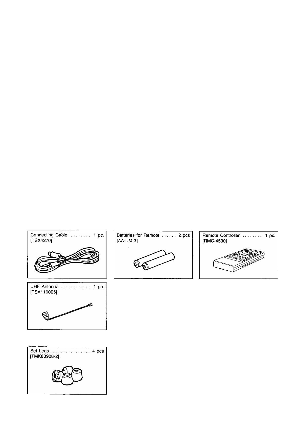
ACCESSORIES
Accessories packed with your satellite receiver {CRD-4500R]
Accessory packed with your power supply [CRD-4500P]
-3-
Page 5
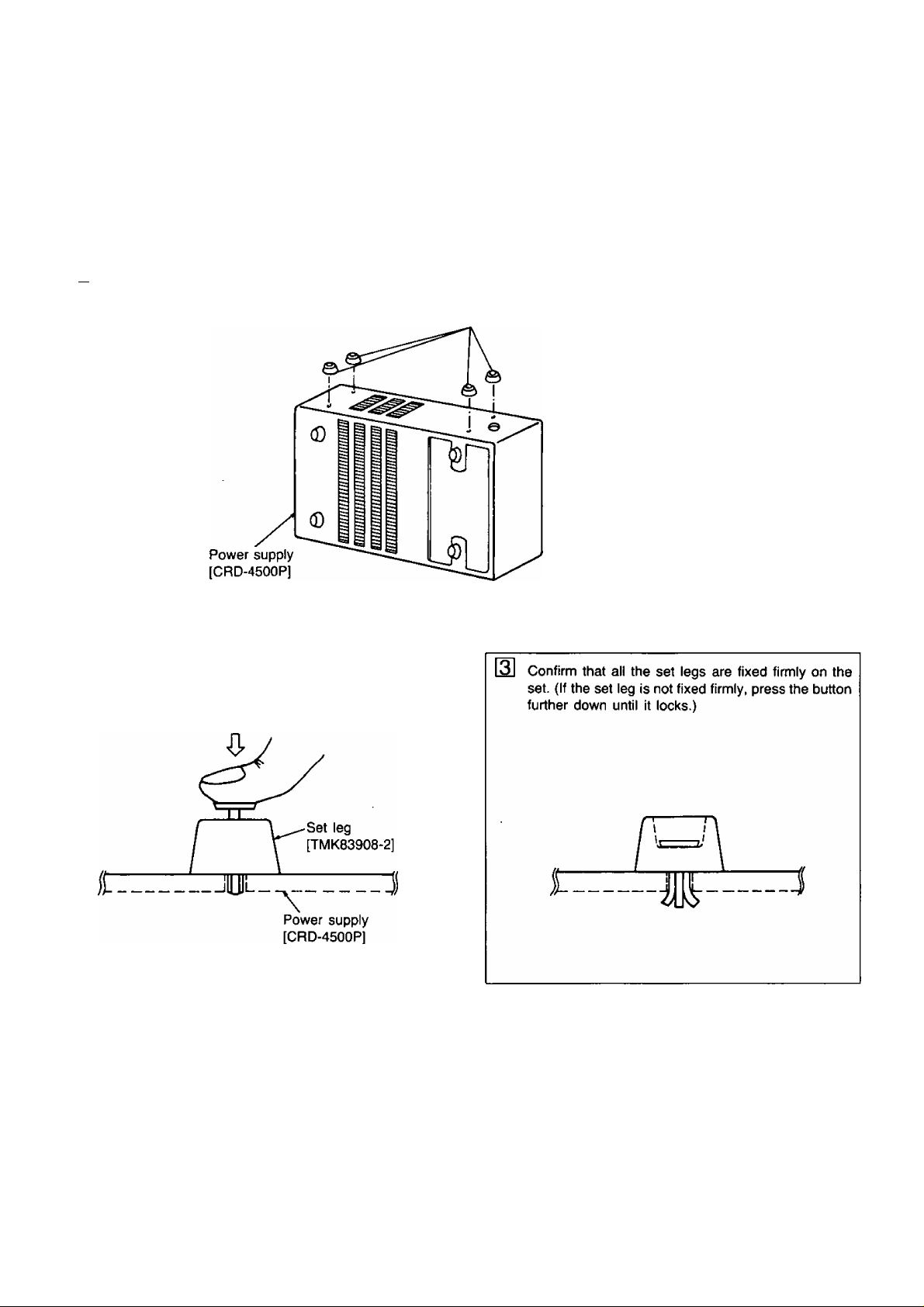
ATTACHMENT OF THE SET LEGS
Attachment of the Set Legs
The power supply may be installed either horizontal or vertical. These are 2 sets of mounting holes for the set legs, and
an extra set of legs supplied with the unit. If it is desired to install the power supply in the vertical position, insert the extra
legs as shown.
m Insert the set legs [TMK83908-2] to the four holes located on the right side of the power supply.
Set legs [TMK83908-2]
2 Press down hard on the button on the upper part
of the set leg.
0
_4_
Page 6
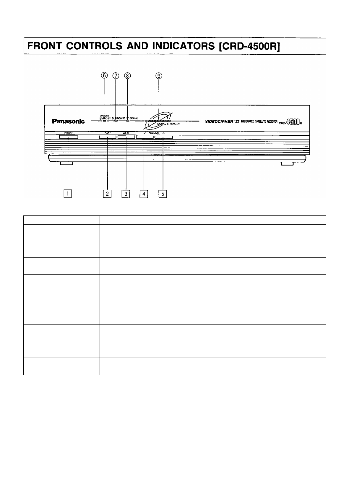
ITEM NO.
PURPOSE
\J] POWER
(T| EAST
WEST
|T| CHANNEL V
\T\ CHANNEL A
^ POWER/STAND BY
^ INDICATOR
^ SURROUND
^ INDICATOR
^ VC SIGNAL
^ INDICATOR
^ SIGNAL STRENGTH
^ INDICATOR
Note: □ ■■■ Controls
O ••• Indicators
Turns the unit ON or OFF.
Causes the antenna to be positioned towards the next east satellite.
Causes the antenna to be positioned towards the next west satellite.
Tunes to a lower channel.
Tunes to a higher channel.
Indicates when the power of this unit is turned ON (red), or the unit is in stand-by mode (green).
Indicates SURROUND mode selected.
Indicates when the system is receiving a VideoCipher n signal.
Indicates the relative strength of the signal being received.
-5-
Page 7
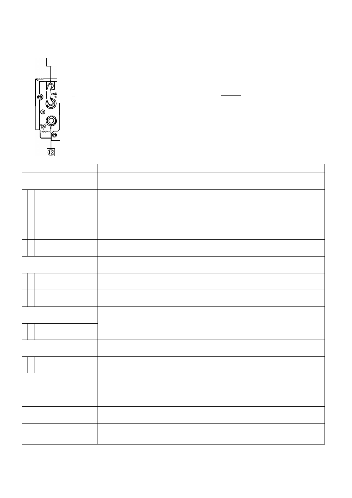
REAR CONTROLS AND TERMINALS [CRD-4500R]
© @
@ © @ -¿I,™ @ @ @ @
^ EXT ANT TV OUT ““composite VIDEO AUDIO V-/
^
------------
ITEM NO.
1^ UHF REMOTE ANT
2ND IF LOOP
0
IF IN/+18V DC
©
OUTPUT TERMINAL
COMPOSITE OUTPUT
©
TERMINAL
VIDEO OUTPUT
0
TERMINAL
AUDIO OUTPUT
^ TERMINALS
/©V
@ © 16 21
m
J
©
@ ©
----------
OUT OUT OUT
GNO VlHVi QH)
dual FEED CONTIOL
ipPv dWa
vgTtZBaüg?
c
25
PURPOSE
Connector for UHF antenna.
Provides 510MHz (2nd IF) signal loop for optional Tl filter Installation.
Input connector for signal from-LNB. Also supplies power to the LNB.
Composite baseband signal to other descramblers.
Video signal to video monitor.
Audio signal to stereo monitor.
FROM POAiER UNIT
©i
/©N ^
n
'©
©
METER ADJUST
16
DUAL FEED CONTROL
©
TERMINALS
1^ IPPV
DATA
©
g| 25 PIN TERMINAL
VIDEO SCAN
21
ON/OFF
EXT. ANTENNA
^ TERMINAL
TV RF OUTPUT
^ TERMINAL
CHANNEL
M CH3/CH4
VIDEOCIPHER
^ ADDRESS NO.
Note: □ Controls
n "■ Terminals
Normalizes the signal strength meter.
Control Voltages to V/H, Ku/C switch for Dual LNB System.
RCA-type connector for future applications.
(Pay per view subscription for special programs when available.)
To connect the power cable from the power supply.
Scans from the lowest frequency channel to the highest while in the “ON” position.
Use to locate satellites when moving anterira. Set Ku or C-Band as appropriate.
Input from external VHF antenna.
VHF signal to TV.
Selects Channel 3 or 4 output of CRD-4500 to the television.
Choose the channel that is not broadcast locally and tune TV to this channel.
You can read the first 8 numbers of your Authorization (Address) Number through this
window. See page 23—26 for directions to read your full 12-digit number.
Use this No. for program subscription.
-6-
Page 8
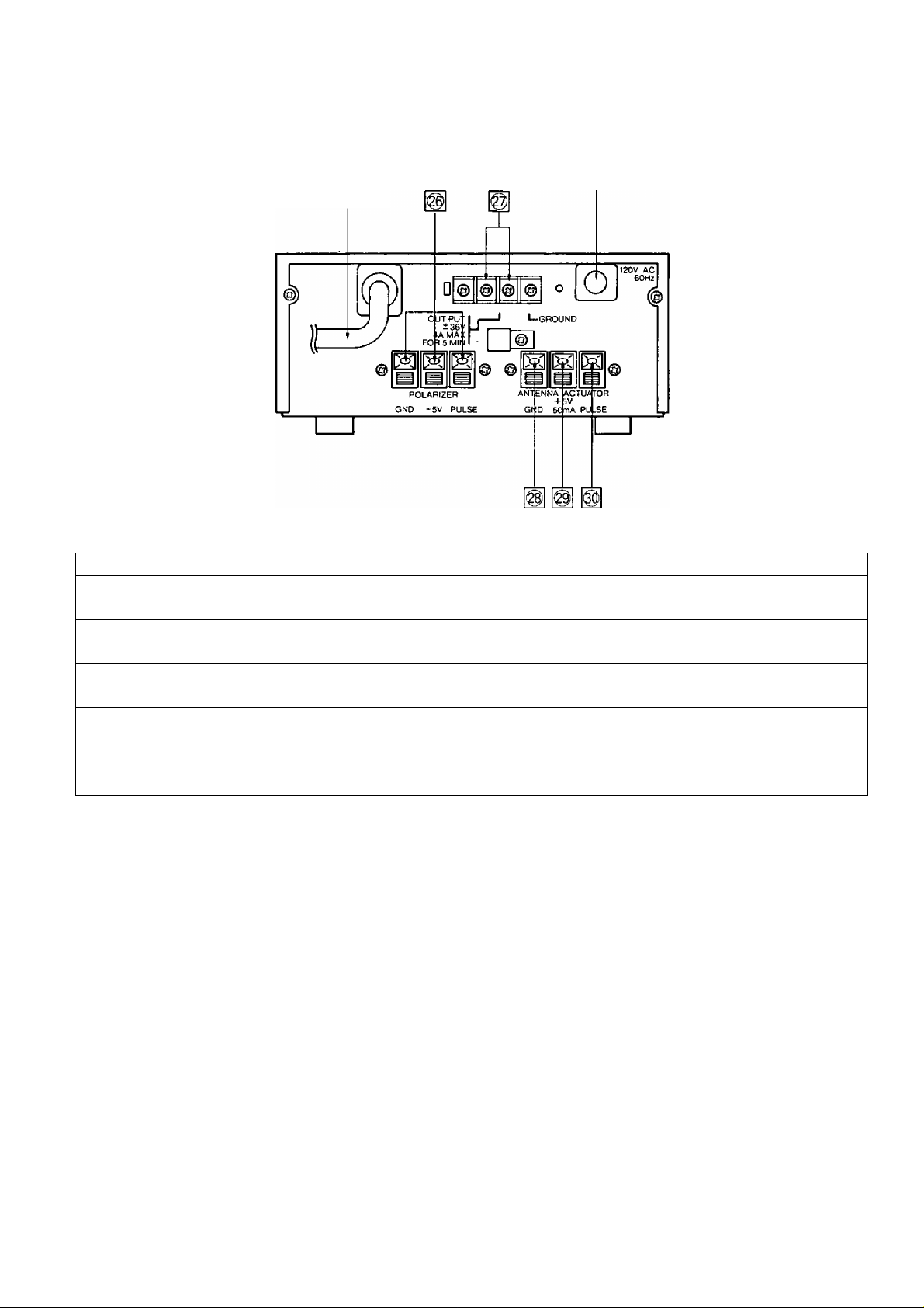
REAR TERMINALS [CRD-4500P]
25P Connecting Cable
ITEM NO. PURPOSE
1^ POLARIZATION CONTROL
^ SIGNAL TERMINAL
AC Cord
Polarizer signal outputs.
@ ±36V/+36V TERMINAL
1^ GND TERMINAL Signal ground conductor from actuator.
g| DC 5V TERMINAL
O PULSE TERMINAL
Note: n Terminals
±36V DC output to actuator motor.
5V DC (50 mA) output to supply Hall or Optical sensor in actuator.
Connection from the sensor pulse output of the actuator.
(Reed switch, hall sensor or optical type)
-7-
Page 9

REMOTE CONTROLLER [RMC-4500]
ITEM N0.
31
38
40
WG 2fT 3/F
0 0,0
o o o
■cmt ' —9JK
o o o
OJB° o ¿5
siWBOUND
0
"EHIer cancel prg
& tZ] CD
SETUP HELP r~ T~ 7IEW
o cp m m
TEXT MESSAGE NE)^ VC[1
VOLUME*'-^ CHANNEL ^
_gzi cp CQ
6/C
t TUNE
I
¿3*
C±3 o
AFC
o-
MUTE
CD-
rasPEKv
rp-
rn
[UK
PURPOSE
47
49
51
53
55
57
59
61
31 POWER
32
NUMBER BUTTONS
33 SAT
AUDIO
34
35
SURROUND
36 ENTER
CANCEL
37
38 PRG
SET UP
39
HELP
40
TEXT
41
Turns the receiver ON and OFF.
Used to program and select satellite and channel by direct access.
Used to select the satellite mode.
Used to set audio frequency.
Used to select surround mode.
Used to input data and for VideoCipher n operation.
Used to delete data and for VideoCipher n operation.
Used to select program mode.
Use this button along with the number buttons to display your Authorization Number and
set up your VideoCipher II channel services and features.
Press this button to read instructional text about setting up your VideoCipher 11 features and
controls.
Some VideoCipher D channels provide text information to their users. These messages may
include news bulletins, program promotions and other special notes.
Use this button to read channel and service related text on your TV screen.
Note: □ •” Controls
-8-
Page 10

ITEM NO.
42 MESSAGE
PURPOSE
Occassionally, your program supplier may have a personal message for your subscription.
If there is a message for you, you will see a flashing asterisk (*) in the upper right corner
of your TV screen. Press this button to read messages on your TV screen.
VOLUME V
43
44
VOLUME A
EAST
45
WEST
46
FINE TUNE V
47
FINE TUNE A
48
49
AUDIO TUNE V
50
AUDIO TUNE A
POLARIZATION V/H Reverses the polarizer signal format, (only in set up mode)
51
AFC ON/OFF
52
53 N/W
Decreases the audio volume.
Increases the audio volume.
Causes the antenna to be positioned towards the east.
Causes the antenna to be positioned towards the west.
Use to optimize picture quality, (only when AFC switch is OFF)
Decreases audio subcarrier frequency.
Increases audio subcarrier frequency.
Activates and deactivates the AFC tuning system, {Automatic Frequency Control)
Selection of bandwidth of audio IF band. (Narrow/Wide)
MUTE
54
55 FAV Displays FAV channel, mode.
56 DISPLAY
57 </>
58 VIEW
NEXT PRG
59
VC II ON/OFF
60
61 CHANNEL V
62
CHANNEL A Tunes the receiver to a higher channel.
Mutes the audio.
Calls up receiver on-screen display data.
Use these buttons to move back and forth in the VideoCipher H text files or to change program
rating limits.
Use this button to check the program title, running time and other information about the
program you are watching.
This button allows you to see information about the next scheduled program on a VideoCipher
n channel.
Turns the VC II ON and OFF when VideoCipher II signal is present.
Tunes the receiver to a lower channel.
-9-
Page 11

BATTERY REPLACEMENT
Open the battery cover by sliding the panel away from the body. Insert the two AA batteries (UM-3) into the battery compartment.
• To install the remote controller batteries,
i) Slide the panel away.
Battery precautions
The incorrect use of batteries can cause electrolyte leakage which will corrode the remote control transmitter or cause the
batteries to explode. The following precautions must be observed carefully.
ii) Replace all batteries at the same time.
iii) Insert batteries with the correct polarity.
iv) Replace the panel.
Don’t mix battery types,
(alkaline and carbon zinc, etc.)
Note:
1. The remote control transmitter should be placed to avoid direct sunlight or heat.
2. Pressing more than two buttons at a time can lead to an incorrect command.
LOW NOISE BLOCK DOWN CONVERTER
• xhe receiver uses Low Noise Block Down Converters (C or Ku-Band LNB) for its microwave interface. The output frequency
range is 950 to 1450MH2. Power is supplied to the LNB via its output F connector.
Note:
The receiver is capable of supplying 18 V DC at 300 milliamps max from the input F connector.
• This is sufficient for one LNB and one Line Amplifier. The breakdown is shown below.
Line Amp (+20 dB)
LNB
If the line amp used only 25 milliamps, then four line amps can be used.
100 milliamps max
200 milliamps max
-10-
Page 12
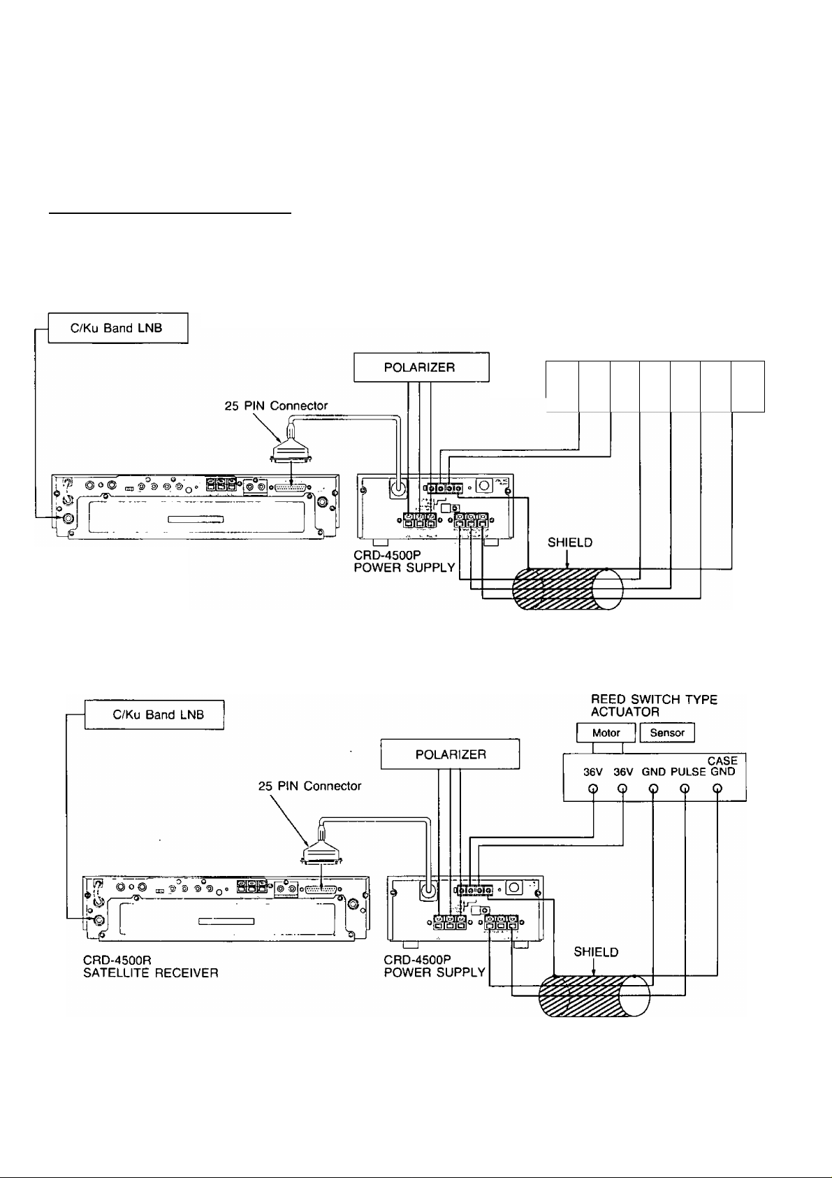
CONNECTIONS
CAUTION:
Inproper connection ot accessories (or connection to incompatible equipment) may damage your unit. All connections should
be made with the power supply unplugged.
[T| I CONNECTION OF OUTDOOR UNIT
• Insert the 25 PIN connector of the power supply [CRD-4500P], to the connector terminal located on the rear panel of
the satellite receiver tCRD-4500R] and tighten the locking screws.
• Connect LNB down converter to the receiver and connect the polarizer and actuator to power supply.
HALL SENSOR AND OPTICAL TYPE ACTUATOR
HALL SENSOR AND
OPTICAL TYPE ACTUATOR
V Gf
> c
Sensor
+5
.V PU
> C
> C
c
LSE G
> C
Motor
36cV 36
) c
4SE
NO
)
CRD-4500R
SATELLITE RECEIVER
REED SWITCH TYPE ACTUATOR
- 11 -
Page 13

[Т] I EXT. ANTENNA AND TV OUT TERMINAL
• To receive an ordinary TV broadcast, turn the
receiver OFF.
• The CRD-4500R has a built-in RF modulator
with RF output (TV OUT) on either Channel 3
or 4. Unless a monitor is used, the RF output
will normally connect to the TV set.
[T| I AUDIOA/IDEO OUTPUT TERMINAL
• The receiver audio out and video out terminals may be used at the same time as the RF output (TV OUT).
VHF Antenna
TV
•X- To Ant. terminal
of TV set.'
^1
Note:
The audio to a monaural monitor can be connected to either the R or L audio output terminal.
[T| I COMPOSITE OUT TERMINAL
• In case of connecting a descrambler other than VideoCipher H, connect it to the composite out terminal.
Page 14

ON-SCREEN DISPLAYS
The CRD-4500 generates a variety of on-screen informational displays. The full display indicates your current satellite,
channel & favorite channel, polarity, antenna position, audio volume level, and more. This information appears automatically
whenever you make any changes or adjustments. You can also check your setting at any time by pressing the I DISPLAY |
button on the remote controller.
\T] Normal on-screen display ___________
• When the equipment is turned on and the I DISPLAY“"] button on the remote controller is depressed, the following
data will be displayed on TV or the monitor screen connected to the equipment.
On-Screen Display’s basic formation
(T) Mode
CD Satellite ■
(D Channel
® V/H select
CD AFC ON/OFF
CD Volume
CD Audio subcarrier
Surround
• Data input choices for the ordinary operation
No. PARAMETER
®
Mode
Satellite
Channel
V/H select
Set up or blank
Automatically appears by
satellite name CD- (‘D
Cband-CH1~CH24
Ku band -CHI-CH32
VERT or HOR
>. . .. . I
DATA INPUT CHOICES
^7—71^
No. PARAMETER
Satellite
®
name/No.
KU/C Band
select
Favorite
page/No.
Antenna
position
-CD Satellite name/No.
Ku/C Band select
Favorite page/No.
® Antenna position
® VC ON/OFF
@ Audio bandwidth
DATA INPUT CHOICES
name
No. -1-9
Ku BAND or C BAND
18 CHs. FAV1-1-FAV1-9,
FAV2-1-FAV2-9 (*2)
0000-9999
AFC ON/OFF ON or OFF
Volume 1—16 bars
Audio
®
subcarrier
5.20-8.60 MHz
©
Note: *1 Displays name of pre-stored satellite.
*2 ” Displays when program received has been stored in Favorite Channel memory.
*3— Displays only when the VideoCipher II signal is being received.
-13-
VC ON/OFF
Audio
bandwidth
Surround
ON or OFF (’3)
WIDE or NARROW
“S" or blank
Page 15

[Example]
A typical display appears below;
•Setup mode
"Galaxy
■CH2
“Horizontal
• AFC ON
©•
■ Volume is 8 bars
■6.20MHz
•G-1
• C Band
®-
■FAV 1-4
©•
■4720
■VC OFF
■NARROW
|~2] VideoCipher n on-screen display
When you receive the VideoCipher n signal, the receiver displays additional data on your TV screen.
For details, please see page 23'-26.
/ GALAXY G-1 C BAND \
CH 2
ANTENNA POS. 4720
AFC ON
\ VOL
-------------
\ AUDIO 6. 20 NARROW /
—
/ SET UP
HOR FAV 1-4
----------------
——
___
1
j
[3] Favorite mode on-screen display
You can program into memory up to 18 of your favorite channels on any satellite.
For details, please see page 21.
-14-
Page 16

PROGRAMMING AND OPERATIONS
1. General Information
The CRD-4500 is designed for automatic operation and simplified installation.
Pre-stored in the memory are the names, relative locations, format and frequency band of over 20 satellites with provisions
for storing 10 new satellites when they are launched into orbit.
The set-up mode is accomplishd using the remote controller with no programming controls located on the receiver. After Set-up,
it is extremely simple to change various settings from the remote controller without resorting to the set-up mode. AFC ON or
OFF, video fine tune, audio tuning, audio bandwidth, antenna fine positioning may all be changed from the remote controller
and are automatically stored in memory on a per-channel basis after adjustment.
Satellite selection, channel selection, and audio tuning may be done either by direct access using the 10 number buttons, or
by using the appropriate slew controls.
2. Single Satellite Operation with Fixed Antenna
■ Indication with [_
1. Program Menu
Press l~PFIG I.
2. Clear Memory
Press I 5 |.
^ means button on remote controller and front panel of the receiver.
• Set-up menu will be displayed unless unit has
been previously programmed. [Fig. 1]
If unit has been programmed display will show
as [Fig. 2].
Press r~1 I then f PRC I.
• All Memory Clear, then press I 9 I | 1 |
I ENTER~~| within 5 seconds.
•
1 SET UP END
2 SELECT DUAL FEED
3 CHANGE WEST LIMIT
4 CHANGE EAST LIMIT
5 ALL MEMORY CLEAR
[Fig-1]
3. Displays
• See [Fig. 3].
SET UP
NOT YET INITIALIZED
ISET WEST LIMITÒ
ANTENNA POS. 5000
(Fig. 3]
-15-
Page 17

4. Limits
Press t Inter I. wait 5 seconds press I ENTER I again.
5. Feed
Press t PRG I .
Set up menu is again displayed. (See [Fig. l])
Press I 2 I Select Dual Feed. Display will show as [Fig. 4].
Press I 1 I for C Band or Ku Band single feed or C Band/Ku Band dual band feed.
[ 2 I for C Band or Ku Band dual feed (H & V).
6. Satellite
Select satellite by pressing I SAT | I NUMBER BUTTONS ] (LETTER)
I NUMBER BUTTONS I (NO.)
• This will automatically set the channel/polarity format for that satellite,
7. Skew
When the satellite is recognized adjust the skew using the I ^ I I >~| buttons on
an even channel.
The word SKEW will be displayed on the screen during the adjustment, SKEW flashes
until the skew limit is reached and the indication stops flashing. Repeat the skew
adjustment for an odd channel.
8. Format
If necessary on a Ku Band satellite, set polarity for each channel by using / V I
button on remote controller while tuning each channel.
9. Program
When all adjustments above are completed press I ^TER~| to enter all settings into
memory.
10. Operate
Press rPR5 3 □□ “SET UP END” to go back to normal operation.
-16-
Page 18

3. Multiple Satellite Operation with Motor Drive Antenna
Indication with | 1 means button on remote controller and front panel of the receiver.
1. Program Menu
Press I PRG I.
2. Clear Memory
Press I 5 I.
3. West Limit
• Set-up menu will be displayed unless unit has
been previously programmed. [Fig. 1]
• If unit has been programmed display will show
as [Fig. 2].
Press I 1 I for SET UP, then I PRG [.
• Alt Memory Clear, then press I 9 I I 1 H
I ENTER~~| within 5 seconds.
Use m (EAST) rw~l (WEST) buttons to
position antenna to desired west limit.
Press I ENTER ~| to set west limit into mem
ory.
Note: 1. If antenna moves in wrong direction, reverse ±36 V leads to motor at
the power supply.
2. Turn on video scan to locate most westerly and (easterly) satellites if
necessary.
4. East Limit
5. Feed
Press I PRG I.
After setting the limits the set up menu should be displayed again. (See [Fig. 1])
Press I 2 I Select Dual Feed. Display will shows as [Fig. 4]
Press r 1 I For C Band or Ku Band single feed or C Band / Ku Band dual band feed
r~2~l For C Band or Ku Band dual feed ( H & V )
Use l~E~l (EAST) rW~l (WEST) buttons to
position antenna to desired east limit.
Press i ENTER ~| to set east limit into memory.
-17-
Page 19

6. Satellite
Press I SAT I I W~| (WEST) buttons on remote controller, or press j WEST 1 button
on front panel of the receiver.
The name of the most easterly available Satellite appears automatically.
Note: 1. If it is not desired to program that satellite into memory, skip to the next
satellite by pressing I SAT I I W I (WEST).
2. If it is desired to program the satellites in an arbitrary sequence, press I SAT I
I NUMBER BUTTONS I (LETTER) I NUMBER BUTTONS I (NO.) to select
a paticular satellite.
3. When it is desired to program a satellite not listed on table 1, use the system
described in section 10.
Press I W I (WEST) button again.
Search for the most easterly satellite using video scan, or if a known channel is active,
set the receiver to that channel.
7. Skew
When the satellite is recognized adjust the skew using the I < I I >~l buttons on
an even channel.
The word SKEW will be displayed on the screen during the adjustment, SKEW flashes
until the skew limit is reached and the indication stops flashing. Repeat the skew adjust
ment for an odd channel.
8. Polarizer Control/Format
The CRD-4500 has been pre-programmed with each satellite format (horizontal or
vertical polarization) according to the program guides. If it appears that the format on
any satellite seems to be opposite to the pre-stored information then follow one of the
procedures below:
A) (Preferred) Rotate the feed horn 90 degress without changing the pre-programmed
format. _______
B) Re-program the format for each satellite by using the I H/V I button on the remote
during the setup mode.
9. Memory
Press I ENTER ~| to set antenna position and skew settings into memory.
10. Additional Satellites
To select the next satellite press I SAT 11 W~| (WEST) or enter satellite name directly
I SAT I I NUMBER BUTTONS I (LETTER) I NUMBER BUTTONS I (NO.) and
repeat 6, 7, 8 and 9 steps above.
-18-
Page 20

11. New Satellites
Satellite Name
C is for C-Band satellite.
0 is for Ku-Band satellite.
Press I S^T~| I C I I 2 I ~ I C I I 9 I for C-Band additional (Fig. 5-0]
or I SAT 1 I O I I 1 I — f O I I 9^ I for Ku-Band additional [Fig. 5-0].
Repeat 6, 7, 8 and 9 steps above.
12. End Programming
After programming all desired Satellites press I PRO I I 1 I "SET UP END’
13. Special Instructions
To cancel or reposition a satellite in memory, or change satellite name.
a. Cancel — Press I PRO I to return to SET UP MODE indicating satellite to be cancelled. Press
after 5 seconds press I CANCEr~| again.
b. Reposition — Locate the new position and enter the satellite name. Press I ENTER ~| — an ERROR 2 message is
displayed. Press I ENTER ~l again after 5 seconds.
c. New Satellite Name — To enter a new satellite name at a programmed position, go to the ^t-up mo^e and enter the
new satellite name. Press I ENTER~| — and an ERROR 3 message is displayed. Press 1~ENTER~| again.
CANCEL I and
# TABLE 1
NAME
S
F
G
K
F
K
T
s
G
T
w
A
A
M
0
S
W
T
F
G
F
F
NUMBER
2
2
2
2 Satcom K2
4 Satcom F4
1 Satcom K1
2 Telstar 302
3 Spacenet 3
3
1
4
1 Anik D1
2 Anik D2
1 Morelos 1
1
1
5 Westar 5
3
3
1
1
5
SATELLITE Kuor C
Spacenet 2
Satcom F2R
Telstar 301
Ku-SAT (Anik C3)
Spacenet 1
Telstar 303
Satcom F3R
Satcom FIR
Satcom F5
Galaxy 2
Galaxy 3
Westar 4
Galaxy 1
LONGITUDE
C 69 “W H
c
72“W
POUCH 1
c 74°W H
Ku 81 °W H
c 83 °W V
Ku 85“W
C 86 °W
c 87“W
c 93.5 “W
c
96°W
c 99° W
c 104.5°W
c 110.5°W
c 113.5°W
Ku
117.5°W
c 120°W
c 122.5°W
c 125°W
c 131°W
c 134“W H
c
139°W
c 143°W V
V
H
V
H
H
V
H
H
H
H
V
H
H
V
V
V
-19-
Page 21

= 4. Operation Using Remote Controlier
■ Indication with I j means button on remote controller.
1. Satellite and Channel Selection
Direct selection of programmed satellite
[Example]
Press I SAT I rF~l m m for SATCOM IR ch 4
or I sAT~i m m m m for telstar 301 ch 15.
The satellite letter must be selected within 5 seconds after pressing I SAT |.
The satellite number must be selected within 5 seconds after selecting satellite letter.
The channel number may be selected at any time afterwards.
2. Satellite Selection
Slew Mode
Press I SAT I I E l (EAST) or I W I (WEST). The next programmed satellite in the
arc will be selected. If the I E~| or I W I buttons are held down, the satellite names
slew through. The antenna starts to move 2 seconds after the desired satellite is selected.
I EAST I I WEST 1 controls on the front panel on the receiver are used to provide
the same operation.
3. Channel Selection
Direct Selection
Press 1 button for channels 1*9, 2 buttons for channels 10 and above.
4. Channel Selection
Slew Mode
Press Channel I A I I V I to slew through the channels.
5. Antenna Fine Positioning
Press I EH (EAST) or | W I (WEST) for fine positioning of the antenna. The antenna
can be moved 8 counts in either direction. The new position will be stored in memory
5 seconds after fine positioning.
6. AFCA/ideo Fine Tuning
AFC (Automatic Fine Tuning) is normally ON. When Terrestrial Interference is present,
or with some Ku Band channels, it may be necessary to off-tune the receiver. Press
I AFC I to turn AFC OFF and then use Fine Tune I A I and I V j until the best
picture is received. These settings will be automatically stored in memory.
-20-
Page 22

7. Audio Tuning
Direct Selection
Press I AUDIO ~| and 3 digit number for subcarrier frequency.
i.e. I AUDIg~| m [X] CX]
This frequency will be automatically stored in memory.
8. Audio Tuning
Slew Mode
Press Audio Tune I A I f V I to slew through all subcarrier frequencies. The last
setting will be automatically stored in memory.
9. Audio NA/V (NarrowWide)
Some audio programs are transmitted in a narrow band mode. After tuning the subcar
rier, use the | NAA/ | button to select the appropriate bandwidth.
The last setting will be automatically stored in memory.
10. Favorite Channel
Up to 18 favorite channels may be stored in the favorite channel memory, 9 on favorite
page 1, and 9 on favorite page 2. To store a channel, tune to the desired program
press I FAV I for favorite page 1, or I FAV j I FAV I for favorite page 2.
Press I ENTER I and I NUMBER BUTTONS 1 (NO.) to place the program that is
being received into the favorite channel memory, in that position.
To cancel a stored selection press 1 FAV I I CANCEL"! I NUMBER BUTTONS 1
(NO.)
To select a stored channel press I FAV I I NUMBER BUTTONS I (NO.)'on favorite
page 1 or I FAV [ I FAV I I NUMBER BUTTONS t (NO.) on favorite page 2.
11 Parental Lock
When the parental lock is on, viewing is restricted to the programs stored in the favorite
channel memory. All other programs are blanked out by a blue screen and the audio
muted. To select the parental lock mode, program the permissable programs into the
favorite channel memory. Press I PRO I I 2 I for parental lock. [Fig. 2]
If the memory has been cleared, enter a new 4 digit password, or use the 4 digit
password already entered.
Press I ENTER I .
Then press I 1 I to turn parental lock ON or OFF. [Fig. 6. 7]
1 SET UP
2 PARENTAL LOCK
[Fig. 2]
Note: When parental lock is on, the SET UP mode is inhibited induding the ALL
MEMORY CLEAR mode.
-21 -
Page 23

Press I NUMBER BUTTONS ] (NO.) for 4 digit password (any desirable number).
Now the password is registered.
Parental lock will be in ON or OFF mode by entering password.
Note:
If you forget or lost your password, you can recover this data by MASTER PASSWORD.
Please refer to the page 29 of this instrutions.
12. Changing Password
1) Press I PR(j 1. [Fig. 2]
2) Press I 2 I for parental lock. [Fig. 6]
3) Press [ ENTER I. [Fig. 7]
4) Press I 2~l for changing password mode. [Fig. 8]
PARENTAL LOCK
Enter password by number buttons, then I ENTER
Password is indicated at on-screen at the 1st entering.
Mark ” will be indicated for 2nd time entering of password.
13. Surround Sound
This mode provides greatiy improved stereo sound when the receiver is connected to
a stereo system or stereo monitor. VideoCipher n stereo audio is greatly enhanced and
monaural transmissions sound as if they are broadcast in stereo. The surround sound
mode may be selected by pressing I SURROUND I on the remote controller.
Note; Surround Sound does not operate on RF out, only operable on baseband audio
with stereo system or stereo monitor.
14. Volume Control
The Volume I A 1 I V I allows adjustment of volume for both RF and baseband
outputs in 16 steps.
The on-screen display indicates the voiume levei when the buttons are depressed.
1 PARENTAL LOCK
2 CHANGE PASSWORD
[Fig. 7]
ENTER PASSWORD
[Fig. 8]
,ON
Urr
Note: When using a Video Cassette Recorder to record a program from the
CRD-4500, adjust the volume to full maximum level.
15. Mute
The 1 MUTEH button mutes the audio. To hear the audio press the [ MUTE I button
again or press Volume I A I I V 1 buttons.
ADDITIONAL NOTICE:
UHF Remote Control
The normal range of the UHF control is greater than 150 feet, with no obstructions.
Houses where a greater range is required, or that have several walls in the path of the
signal may have problems with reliable remote operation. In these cases it mey be
necessary to relocate the UHF receiving antenna to a different location. Unscrew the
antenna from the back of the receiver and reconnect it using a length of coaxial cable
while testing for a location where signals can be received reliably from all control areas.
-22-
Page 24

5. VideoCipher n Operation
Note: Indication with
I means button on remote controller and front panel of the receiver.
■ VideoCipher n Authorization
To view scrambled programming, you will need to be authorized from your local program supplier or contact the program
distributors directry. They will set up an account for you and authorize your unit to descramble selected channels.
You can obtain the program distributor’s telephone number by tuning your satellite receiver to the channel that you wish
to watch. Most services broadcast subscription information on audio subcarriers (usually 6.8 MHz). Some VideoCipher II
channels will display a subscription phone number on the screen when your tune them in.
Your program distributor will need your address number, which can be read off your TV screen by pressing a few buttons
on the remote controller.
D] Getting Authorized
1. Turn your TV satellite system ON.
2. Use your program guide to check which satellite and channel has the VideoCipher II service that you wish to subscrible to.
3. Tune to the VideoCipher II channel. The VIDEOCIPHER SIGNAL indicator will light up, turn ON VideoCipher II, you
will see only a black screen (or text) until you subscribe to the channel and receive authorization.
When you are tuned to a VideoCipher n channel, the VIDEOCIPHER SIGNAL indicator should be ON.
4. Press [ SET UP~n and [T] on the remote controller. Your
TV will display the following;
A. Your Authorization (Address) Number will appear on the
screen. The first 8 digits of this number should be the
same as those in the window on the back of your receiver.
The last 4 digits on the screen are for Program Distributor
use. Write all 12 numbers in the page 1 of this Manual.
B. Your TV should also show 2 signal strength numbers.
UNIT 1000 0082 FF 8A
SIGNAL LEVEL48/45
SERVICEID:NONE
LOCATION:NOT SET
For the best system performance, both numbers should
be between 45 and 50. For example, 46/48 is good, but
43/41 is not. Maximum strength is 50. Dish alignment and
weather conditions can affect the VideoCipher signal
strength.
Some VideoCipher II channels may require video fine
tuning to improve picture quality and reduce the channel
lockup time.
5. Call the program service that you want to subscribe to.
They will ask for your Authorization Number and other billing
information.
6. Once the Authorization Messages are received by your
receiver, the SERVICE ID line will say something other than
NONE. You will probably see [AO] after SERVICE ID.
The LOCATION line will say SET.
UNIT:1000 0082 FF 8A
SIGNALLEVEL:48/45
SERVICEID:AO
LOCATION:SET
-23-
Page 25

7. Press I VIEW I. You should see the current program on
the VideoCipher II channel. You should also see information
about the program (Title, Running Time, Start Time). Check
your program guide to verfiy that you are on the correct chan
nel. This text information will drop off the screen in about 3
seconds. If you wish to display it again, press I VIEW |.
Note: Some VideoCipher channels may not have title dis
play when you press [ VIEW 1.
[2] VIDEOCIPHER E SETUP
Once you have received authorization, you can turn on and view a VideoCipher n channel just as you would on unscrambled
channels. However, VideoCipher II channels provide additional features and services. Here’s how to use them.
The following features can be used only on VideoCipher II channels.
VIEW
Press the I VIEW | to see information about the current pro
gram being broadcast on the channel.
This will include program title, running time and rating.
After 3 seconds, this program information will disappear from
the screen.
The I VIEW I is also used when you want to exit from a
VideoCipher II setup routine without completing it, to watch your
regular program.
HELP
Press I HELP I when you are using VideoCipher II features
and need an explanation of the procedure. You will be able to
read HELP messages on your TV. If you still cannot understand
the procedure, press I VIEW | and consult .the Manual.
SETUP
Press I SETUP~1 is used with the number buttons to customize
your VideoCipher II features.
If you press I SETUPn, you will see the following menu on
your TV.
1. Installation
2. Unit Setting
3. Rating Ceilling
4. Rating Password
You can choose one of these VideoCipher П setup activities by pressing one of these number buttons.
1. Installation
Press I SETUP~1 and Q] to display your Authorization Number and Signal Strength on your TV screen. Your program
supplier will need these numbers to authorize you for VideoCipher E program reception.
-24-
Page 26

2. Unit Setting
Personal Messages
VideoCipher II program suppliers may send you messages about your service subscription.
These may concern you account balance, new service, or other information. Messages can be read on your TV.
1. A flashing asterisk [*] will appear on the screen to inform you that a message is stored for you,
2. To read the message, press [ MESSAGE I.
You can set your system so that the [*] does not show on
the screen.
1. Press I SETUP I and [H.
2. The display will read: MESSAGE PROMPT ENABLED
(ON) or MESSAGE PROMPT DISABLED (OFF).
3. Press {2} to switch back and forth and set the prompt ON
or OFF.
Second Language Audio
Some VideoCipher II channels may offer second languages on their programs.
1. To listen to an ALTERNATE language, press I SETUP ~| and (1].
2. Press Q] to select PRIMARY (usually English) or ALTERNATE (the second language).
3. Ratings Ceilings
Your receiver allows you to set a rating limit for you
VideoCipher n channels.
Your receiver uses rating ceilings similar to the G, PG, PG-
13, R and X ratings used by the motion picture industry.
You can prevent viewing all rated VideoCipher II channel
programs above the level that you set it at.
For example, if you set the level at PG-13, your system will
allow only G, PG and PG-13 rated programs.
Both R and X-rated programs will be blocked.
r n
1. Press I SETUP I and [3].
2. Enter your password if one has been set, if no password
has been set, proceed to the next step.
3. Use the I < |/[~~>~n to change the . rating ceiling.
AUDIO MODE IS
PRIMARY
(PRESS t FOR)
(ALTERNATE)
MESSAGE PROMPT IS
ENABLED
(PRESS 2 TO)
(DISABLE)
RATING CEILING:R
PROGRAM RAT)NG:G
(ENTER THE RATING)
(PASSWORD: )
RATING CEILING:R
PROGRAM RATING:G
(• . •. OR ENTER')
J
4. Rating Password
Passwords are used to control access to the rating ceilings. We suggest that you pick a password number that is easy
to remember: your zip code, date of birth phone number, street address.
It you forget your password, you will need to contact your program distributor to have it reset.
-25-
Page 27

If you don’t want password control:
1, Press I SETUP "I and S],
2. Press I ENTER~| twice when the screen prompts you to enter
a new password.
To set or change a password:
1. Press I SETUP I and 0.
f ENTER A NEW 1
PROGRAM RATING '
PASSWORD
0-8 DIGITS
PLUS 'ENTER'
^ (PASSWORD: ) J
2. Key in your new password (up to 8 digits) and press
I ENTER I.
(a) If the system has a password stored, you will need to key it
in and press [ ENTER~| before the system will accept a new
one.
__________
© Key in the new password, and press I ENTER~1-
3. The screen will ask you to enter the new password a second
time and press I ENTER~| to confirm it.
Г REENTER THE NEW I
PASSWORD '
FOR VERIFICATION
0-8 DIGITS
PLUS 'ENTER'
^ (PASSWORD: ' J
The screen will then tell you that the password has been
changed and then return you to the main SETUP menu.
Program Messages
VideoCipher n program suppliers offer a wide variety of services, some of which require restrictions on viewing. When there
is a viewing restricion, you will see one of the following messages, rather than the program that is showing:
No Subscription
This message indicates that your receiver has not been authorized to receive this channel, or you have lost authorization.
Contact your program supplier to receiver or renew your authorization.
Blackout
This message indicates that a specific program is not available in your geographic area.
Program Locked Out
This message will appear if the program curretly being broadcast on that channel exceeds the rating ceiling that you have
set. You must change the rating ceiling if you want to view the program. (See Rating Ceilings and Rating Password).
Next Available Program
This VideoCipher II feature allows you to quickly check upcoming programs.
1. Turn to the VideoCipher n channel that you wish to watch.
2. Press f NEXT PRG~~l.
3. You will see a message listing the title, rating, start time and other information about the next program.
4. You may also see one of the other VideoCipher II service messages (No Subscription, Blackout, etc.)
Text Services
Some VideoCipher II channels may broadcast news bulletins, program information and other text over the channel.
To view these services:
1. Turn to a VideoCipher II channel.
2. Press rtEXTH.
3. Use the I < |/|~~>~~| to move back and forth within the text.
4. You can move to a specific page by keying in a 3-digit page number. For example, page 6 would be 006. If will usually
take several seconds before the page is displayed.
If you request a page that is not in the file (for example page 006 in a 5 page file), the screen will not change.
- -
Page 28

DIAGNOSTICS
Error Indication (Error is indicated by a flashing message)
No.
(D
ON SCREEN
ERROR-2
(D ERROR-3
(D
ERROR-6
®
ERROR-8
CAUSES METHODS OF CORRECTION
When trying to enter the same satellite name/
No. into memory at more than one satellite pos
itions.
When trying to enter more than two satellite into
memory at one single satellite positions.
When feedback pulses are not being received.
A. When the actuator is fully extended or
retrected in the initialize mode or in the
manual mode.
B. When the actuator is not correctly con
nected with CRD-4500P or the connection
is broken, (no pulse being received)
“ERROR-2” and “ERROR-3” occurred simul
taneously. (The same satellite name was tried
to be stored at the same antenna position.)
Press 1 ENTER | to release the error. The
satellite is stored at the position selected later.
Press 1 ENTER I to release the error. The
priority is given to the name of the satellite
selected later and stored accordingly.
Press ( EAST |/1 WEST 1 to move the
antenna position slightly in the reverse direc
tion.
Check that antenna is not into a stop, or that
cable connections to actuator are secure.
Press 1 CANCEL 1.
This information has been already stored.
(D
ERROR-!
THERMAL OVER
®
LOAD
Memory error
If the internal temperature (CRD-4500P)
increases and the thermal protective circuit
(Disable circuit) functions, the unit will not be
operative.
Turn the power off and Call your dealer.
Turn unit OFF to allow to cool. (Wait approx.
10 min. to operate)
Check actuator and antenna for free move
ment.
-27-
Page 29

TROUBLESHOOTING
Before calling for service, determine symptoms and attempt these simple solutions shown below. These checks apply to your
TV or monitor as well as the CRD-4500.
PROBLEM
No operation
Picture
Sound
Picture
Sound
Picture
Remote control
Antenna
SYMPTOM
No indicator lights
None
Noisy (Snow)
distorted
Horizontal hum
(Bar rising across screen
caused by a ground loop)
Doesn’t work
(CRD-4500R is still operable
from front panel controls)
Doesn’t move
CHECK
• Power cord
• Call dealer
• Brightness and sound controls on TV Monitor
• Call dealer
• No transmission on channel selected try another channel
• Antenna adjustment
• Check cable connections
• TV not tuned to output channel of receiver CH3/CH4
• Check polarization and antenna position
• Call dealer
• Ground loop problem
• Call dealer
• Test at different distances
• Make sure UHF receiving antenna is connected properly
• Replace batteries
• Call dealer
• Check antenna for obstruction
• Check electrical connections from receiver to the power
supply and antenna.
• Check antenna actuator load, if too heavy caused by freez
ing.
• Call dealer
-28-
Page 30

SPECIFICATIONS
Satellite Receiver CRD-4500R
IF
Input Frequency:
Input Impedance:
Noise Figure:
Input Signal Level:
Number of Channels:
C-Band
Ku-Band
Bandwidth (-3dB):
Threshold:
Demodulator:
Video
De-emphasis:
Frequency Response:
DG & DP:
Output Impedance:
Output Level:
Composite
Output Impedance:
Output Level:
Frequency Response:
Audio
Subcarrier Audio:
Tuning Range
Bandwidth
Mode
Frequency Response
950-1450MHz
75 ohms
15dB max.
-65—30dBm
24ch
32ch
27MHz, typical
less than 8dB C/N
PLL Demodulator
525 lines, CCIR Rec 405-1
10kHz-4.2MHz, ±1dB
5%, 5°
75 ohms
1 Vp-p, typical
75 ohms
1 Vp-p, typical
lOkHz-BMHz, ±2dB
5.2~8.6MHz
150kHz, 280kHz
Mono
50Hz-15kHz, ±2dB
Power Supply CRD-4500P
Output:
Sensor Type;
Power Consumption:
Dimensions (WxHxD);
Weight:
36V DC, 4A max,
for 5 minutes
Hall effect:
Reed switch:
Optical switch
46W
7 3/32”X2 ■'3/ie”x 11”
(180x75x280mm)
11 Vs lbs. (5.0kg)
VC Mode Audio:
Mode
Frequency Response
Output Impedance:
Output Level:
Stereo/Mono
20Hz~18kHz, ±2dB
600 ohms
1 Vp-p, typical
VHF Output
Impedance:
Channel:
Output Level:
LNB Power:
75 ohms
CH3/CH4
65dB jLiV, typical
18V DC, 300mA
General
Power Source:
Dimensions (W x H x D):
Weight:
Polarizer;
Specifications subject to change without notice.
117V AC±10%
14 3/i6”x2 '‘5/-,6"x11’
(360 X 75 X 280mm)
9 3/4 lbs. (4.4kg)
Servo output
MASTER PASSWARD; 3872
-29-
Page 31

Panasonic Industrial Company, Division of Matsushita Electric Corporation of America
One Panasonic Way Secaucus, New Jersey 07094
PANASONIC SATELLITE RECEIVING
PRODUCT LIMITED WARRANTY
Panasonic Industrial Company will, at its option, either repair or replace this Panasonic Satellite Receiving Product, free of
charge, in the U.S.A. and Puerto Rico, in the event of a defect in materials or workmanship as follows;
PARTS: New or rebuilt parts in exchange for defective parts for one (1) year after date of original purchase. Batteries are not
warranted.
LABOR: Mail-in service for one (1) year after original purchase.
SERVICE PROCEDURE: If a problem with the Panasonic Satellite Receiving Product develops during or after the warranty
period, contact your dealer for assistance and instructions or call toll-free 800-447-4700 to obtain the name of the nearest
Panasonic Authorized Servicenter.
TECHNICAL ASSISTANCE: If you have difficulty operating this Panasonic Satellite Receiving Product please contact your
dealer or Distributor first.
If further assistance is required please contact Panasonic Technical Support Dept, at (201) 392-HELP, 9:00AM to 5:00PM, E.S.T.
If instructed to return the product to Panasonic Industrial Company Senrice Division, or Authorized Servicer, carefully pack
and send it prepaid, adequately insured, and, if possible in the original carton. Attach a postage-affixed letter detailing the
complaint, to the outside of the carton and tape a piece of paper with your name and address to the product.
This warranty only covers failures due to manufacturing defects which occur during normal use. It does not cover failure due
to damage which occurs in shipment or failures which are caused by products not supplied by Panasonic Industrial Company
or Panasonic Company or failures which result from accident, misuse, abuse, neglect, mishandling, misapplication, alteration,
adjustment of controls or improper maintenance, modification, inadequate signal pickup or service by anyone other than your
dealer or the Panasonic Servicenter or damage that is attributable to acts of God.
LIMITS AND EXCLUSIONS: There are no other express warranties except the one listed above.
PANASONIC INDUSTRIAL COMPANY assumes no responsibility or liability to reimburse or compensate owners/users of an
IRD (intergrated receiver/descrambler unit) for the loss of paid subscription television programming, such as HBO, Showtime,
Cinemax, etc., in the event your IRD unit should require servicing. THE OWNER/END-USER OF THE IRD UNIT IS ADVISED
TO NOTIFY EACH PROGRAMMER BEING PAID A SUBSCRIPTION FEE THAT YOUR IRD UNIT IS ‘out-of-service’ AND
THAT YOU WISH TO SUSPEND YOUR SUBSCRIPTION DURING THE PERIOD YOUR IRD UNIT iS INOPERABLE.
PANASONIC INDUSTRIAL COMPANY SHALL NOT BE LIABLE FOR INCIDENTAL OR CONSEQUENTIAL DAMAGES ARIS
ING OUT OF ANY BREACH OF THIS WARRANTY. DURATION OF IMPLIED WARRANTIES, IF ANY, IS LIMITED TO ONE
(1) YEAR.
Some states do not allow the exclusion or limitation of incidental or consequential damages or limitation on how long an implied
warranty lasts, so the above exclusion or limitation may not apply to you.
This limited warranty gives you specific legal rights and you may also have other rights which may vary from state to state.
If a problem with your product is not handled to your satisfaction, then write to the Consumer Affairs Division at the following
address:
AV Systems Group
Panasonic Industrial Company, Division of Matsushita Electric Corporation of America
One Panasonic Way Secaucus, New Jersey 07094
Attn: Customer Care 2A3.
-30-
Page 32

Panasonic.
VIDEO/COMMUNiCATION DIVISION
Panasonic Industrial Company
Division of Matsushita Electric Corporation of America
One Panasonic Way, Secaucus, NJ 07094
O
Printed in Japan
S1288 JT7T0
 Loading...